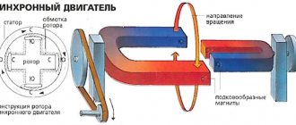
What is an autotransformer?
From a school physics course we know that the simplest transformer consists of two coils wound on iron cores.
The magnetic field of alternating current, powered through the terminals of the primary windings, excites electromagnetic oscillations in the second coil, with a similar frequency. When a load is connected to the terminals of the working winding, it forms a secondary circuit in which an electric current arises. In this case, the voltage in the formed electrical circuit is directly proportional to the number of turns of the windings. That is: U1/U2 = w1/w2, where U1, U2 are voltages, and w1, w2 are the number of full turns in the corresponding coils.
Figure 1. Diagram of a conventional transformer and autotransformer
The autotransformer is designed a little differently. It essentially consists of one winding, from which one or more taps are made, forming secondary turns. In this case, all windings form not only an electrical, but also a magnetic connection with each other. Therefore, when electrical energy is supplied to the input of the autotransformer, a magnetic flux arises, under the influence of which an emf is induced in the load winding. The magnitude of the electromotive force is directly proportional to the number of turns forming the load winding from which the voltage is removed.
Thus, the formula given above is also valid for an autotransformer.
A large number of leads can be drawn from the main winding, which allows you to create combinations for removing voltages of different magnitudes. This is very convenient in practice, since voltage reduction is often required to power several units of electrical appliances using different voltages.
The difference between an autotransformer and a conventional transformer
As can be seen from the description of the autotransformer, its main difference from a conventional transformer is the absence of a second coil with a core. The role of secondary windings is performed by separate groups of turns having a galvanic connection. These groups do not require separate electrical insulation.
This device has certain advantages:
- the consumption of non-ferrous metals used for the manufacture of such equipment has been reduced;
- energy transfer is carried out by the influence of the electromagnetic field of the input current, and thanks to the electrical connection between the windings. Consequently, energy loss is lower, which is why autotransformers have higher efficiencies;
- light weight and compact dimensions.
Despite the design differences, the operating principle of these two types of products remains unchanged. The choice of transformer type depends, first of all, on the goals and tasks that have to be solved in electrical engineering.
Types of autotransformers
Depending on which networks (single-phase or three-phase) the voltage needs to be changed, the appropriate type of autotransformer is used. They are single-phase or three-phase. To transform current from three phases, you can install three autotransformers designed for operation in single-phase networks, connecting their terminals with a triangle or an asterisk.
Transformer winding connection diagram
There are types of laboratory autotransformers that allow you to smoothly change the output voltage values. This effect is achieved by moving a slider along the surface of the open part of a single-layer winding, similar to the operating principle of a rheostat. Turns of wire are applied around a ring-shaped ferromagnetic core, along the circumference of which the contact slider moves.
Autotransformers of this type were widely used throughout the USSR during the era of mass distribution of tube televisions. At that time, the network voltage was unstable, which caused image distortion. Users of this imperfect technology had to adjust the voltage to 220 V from time to time.
Before the advent of voltage stabilizers, the only way to achieve optimal power parameters for household appliances of that time was the use of LATR. This type of autotransformer is still used today in various laboratories and educational institutions. With their help, electrical equipment is adjusted, highly sensitive equipment is tested, and other tasks are performed.
In special equipment where the loads are insignificant, DATR autotransformer models are used.
Autotransformer LATR
There are also autotransformers:
- low power, for operation in circuits up to 1 kV;
- medium-power units (more than 1 kV);
- high-voltage autotransformers.
It should be noted that for safety reasons, the use of autotransformers as power transformers to reduce voltages exceeding 6 kV to 380 V is limited. This is due to the presence of a galvanic connection between the windings, which is not safe for the end user. In case of accidents, it is possible that high voltage will reach the powered equipment, which is fraught with unpredictable consequences. This is the main disadvantage of autotransformers.
Designation on diagrams
It is very easy to distinguish the autotransformer in the diagram from the image of a conventional transformer. A sign is the presence of a single winding connected to one core, indicated by a thick line in the diagrams. Windings are shown schematically on one or both sides of this line, but in an autotransformer they are all connected to each other. If the turns are shown autonomously in the diagram, then we are talking about a regular transformer.
Homemade device
Normal battery voltage when disconnected from the vehicle is between 12.5 V and 15 V. Therefore, the charger must produce the same voltage. The charge current should be approximately 0.1 of the capacity, it can be less, but this will increase the charging time. For a standard battery with a capacity of 70-80 Ah, the current should be 5-10 amperes, depending on the specific battery. Our homemade battery charger must meet these parameters. To assemble a charger for a car battery, we need the following elements:
Transformer. Any old electrical appliance or one purchased on the market with an overall power of about 150 watts is suitable for us, more is possible, but not less, otherwise it will get very hot and may fail. It’s great if the voltage of its output windings is 12.5-15 V and the current is about 5-10 amperes. You can view these parameters in the documentation for your part. If the required secondary winding is not available, then it will be necessary to rewind the transformer to a different output voltage. For this:
- Remove all unnecessary secondary windings, leaving only the primary.
- Calculate the required number of turns and wire cross-section for the appropriate voltage and current. For this there are special calculators and formulas from the physics course. The required wire diameter is calculated according to the table below. The wire must be in varnish insulation. And the number of turns is determined by the ratio: U1/U2=N1/N2. It follows that if your primary winding consists of 480 turns, then to obtain 13 Volts at the output you need to wind only 26 turns, since the network voltage is 220 Volts.
- After this, lay the wire on the base, turn to turn, insulating between the layers with paper or electrical tape in several layers. Bring out the end and beginning of the windings and securely fasten them to the body. To solder wires to them, strip the insulation with a knife.
- To reduce noise and vibration, as well as improve insulation, you can impregnate the device with paraffin.
Thus, we found or assembled the ideal transformer to make our own battery charger.
We will also need:
- 4 diodes. Any diodes with a current of at least 10 amperes will do. Some of the most popular: imported - 10A10, domestic - D242A, 2D203A, KD213B. Or diode bridges, for example: KVRS1001, KVRS1002 and their analogues.
- 4 radiators for diodes. You can, of course, do without them at low currents of the order of 3-5 Amperes. But this can lead to their rapid failure, so radiators with an area of 32 square meters are required. cm or 128 sq. cm for diode bridge. They can be made from sheet aluminum or use coolers from computers and motherboards.
- Demountable electrical plug or power cord.
- Copper wires with a cross-section of at least 2.5 square meters. mm.
- Fuses for 0.5A and 10A.
- Heat shrink tubing or electrical tape.
- A dielectric plate, or even better, a casing, such as plywood or plastic.
- A piece of nichrome wire from an electric stove.
- Multimeter or voltmeter with ammeter.
- Soldering iron, solder and flux (rosin or LTI-120).
- A few more radio components if we want to make a device with protection and automatic shutdown.
Having prepared all the materials, you can proceed to the process of assembling the car charger itself.
To make a charger for a car battery with your own hands, you need to follow the step-by-step instructions:
- We create a homemade battery charging circuit. In our case it will look like this:
- We use transformer TS-180-2. It has several primary and secondary windings. To work with it, you need to connect two primary and two secondary windings in series to obtain the desired voltage and current at the output.
- Using a copper wire we connect pins 9 and 9'.
- On a fiberglass plate we assemble a diode bridge from diodes and radiators (as shown in the photo).
- We connect pins 10 and 10' to the diode bridge.
- We install a jumper between pins 1 and 1'.
- Using a soldering iron, attach a power cord with a plug to pins 2 and 2'.
- We connect a 0.5 A fuse to the primary circuit, and a 10-amp fuse to the secondary circuit, respectively.
- We connect an ammeter and a piece of nichrome wire into the gap between the diode bridge and the battery. One end of which is fixed, and the other must provide a moving contact, thus the resistance will change and the current supplied to the battery will be limited.
- We insulate all connections with heat shrink or electrical tape and place the device in the housing. This is necessary to avoid electric shock.
- We install a moving contact at the end of the wire so that its length and, accordingly, the resistance are maximum. And connect the battery. By decreasing or increasing the length of the wire, you need to set the desired current value for your battery (0.1 of its capacity).
- During the charging process, the current supplied to the battery will itself decrease and when it reaches 1 ampere, we can say that the battery is charged. It is also advisable to directly monitor the voltage on the battery, but to do this it must be disconnected from the charger, since when charging it will be slightly higher than the actual values.
It will be interesting➡ The gimlet rule
The first start-up of the assembled circuit of any power source or charger is always carried out through an incandescent lamp, if it lights up at full intensity - either there is an error somewhere, or the primary winding is short-circuited! An incandescent lamp is installed in the gap of the phase or neutral wire feeding the primary winding.
This circuit of a homemade battery charger has one big drawback - it does not know how to independently disconnect the battery from charging after reaching the required voltage. Therefore, you will have to constantly monitor the readings of the voltmeter and ammeter. There is a design that does not have this drawback, but its assembly will require additional parts and more effort.
A visual example of the finished product
What is LATR?
LATR - laboratory adjustable autotransformer - a device designed to regulate the voltage supplied from a single-phase or three-phase alternating current network. Using the input voltage, LATR either increases or decreases it. LATR is also designed for setting up and testing a variety of electrical equipment in a laboratory or research center. Working with it implies knowledge and understanding of basic physical laws, in particular Ohm's law.
LATR is used for research purposes, for testing AC equipment, setting up radio equipment, for testing highly sensitive medical equipment and industrial equipment. Widely used in all electrical equipment service centers for testing. It is also used for heating nichrome thread, in animal husbandry, to regulate the heating temperature of incubators and brooders.
LATR is the easiest way to obtain a given voltage, or change it for research and tests. By turning the handle with the brush assembly, the alternating voltage from the winding at the output of the LATR is adjusted in the range from 0 to 300 Volts.
The SUNTEK company specializes in the production of laboratory autotransformers of various capacities. SUNTEK LATERS are distinguished by their convenience (the RED series has a number of additional functions), build quality, reinforced brush assembly, wide range of output voltages, form and functionality. The liquid crystal display of SUNTEK LATRs allows you to control the output voltage with an accuracy of up to a volt, which cannot be said about the dial indication, which has a large error.
When using LATR, you should understand the amount of current passing through the winding of the LATR. This is the main indicator. Due to the absence of galvanic isolation and the presence of electrical connection, the current of the primary winding will practically be the current of the secondary winding.
Operating principle of an autotransformer
And now, for a better understanding of the basic operating principle of autotransformers, let’s consider the processes that occur in them.
As an example, we will take an autotransformer, which can either increase the output voltage or decrease it relative to the initial one. For ease of calculation, the total number of turns of copper wire is 20; it looks like this:
As you can see, this model already has four connection points to the common winding: A1, a2, a3 and X.
A source of alternating electric current is connected to contacts A1 and N, for example, the power supply from a standard city electrical network, with voltage (U1), in our case it is standard 220V. There are a total of 18 turns of copper wire between these points; this section of the spiral is designated as W1; it is considered the primary winding of the autotransformer.
Types of LATRs
Main elements of LATR SUNTEK
Single-phase
This type of LATR produces single-phase alternating regulated voltage. It is very often used by radio amateurs, as it allows you to select any low-voltage alternating voltage.
Three-phase
This type of LATR is used in industrial electronics. A three-phase voltage is supplied to its input, and at the output we get the same three phases, but with a smaller amplitude. This LATR allows you to change the voltage amplitude of all three phases simultaneously. Roughly speaking, these are three single-phase LATRs, which are located in the same housing and which change the voltage equally.
Classification of species
Typically, the devices in question are used in industrial and domestic applications that are designed for low power consumption. They are also effective for connecting systems operating at different voltages. This explains the variety of types of autotransformers.
The products in question are:
- According to the degree of external protection of the case - devices intended to operate outside are equipped with a waterproof case.
- According to technical characteristics - operating frequency range, maximum primary and secondary voltage values, maximum secondary current, power and temperature.
- According to the type of electrical network in which they operate - single-phase or three-phase.
Single-phase (left) and three-phase (right) - Depending on the output voltage, autotransformers can be step-up or step-down. A special class is formed by devices with sliding taps. An important characteristic that is taken into account when choosing is the type of core - laminated, split and toroidal.
1a – transformer, 1b – step-down, 1c – step-up
Main types of autotransformers
- VU-25-B - serves to equalize secondary currents in differential protection of power transformers.
- ATD - power 25 W, takes a long time to saturate, has an old design and is therefore used very rarely.
- LATR-1 - designed for networks with a voltage of 127 V.
- LATR-2 - used with a voltage of 220 V.
- DATR-1 - designed for light loads.
- RNO - designed for heavy loads.
- ATCN - used in measuring television devices.
Application area
The features of the autotransformer allow it to be used in everyday life and various areas of industry.
Metallurgical production
Regulated autotransformers in metallurgy are used to check and adjust the protective equipment of rolling mills and transformer substations.
Utilities
Before the advent of automatic stabilizers, these devices were used to ensure the normal operation of televisions and other equipment. They consisted of a winding with a large number of taps and a switch. He switched the output of the coil, and the output voltage was controlled using a voltmeter.
Currently, autotransformers are used in relay voltage stabilizers.
Reference! In three-phase stabilizers, three single-phase autotransformers are installed, and adjustment is made in each phase separately.
Chemical and petroleum industry
In the chemical and petroleum industries, these devices are used to stabilize and regulate chemical reactions.
Production of equipment
In mechanical engineering, such devices are used to start electric motors of machine tools and control the rotation speed of additional drives.
Educational establishments
In schools, technical schools and institutes, LATRs are used to perform laboratory work and demonstrate the laws of electrical engineering, and experiments on electrolysis.
How to make a LATR with your own hands
It is quite possible to make this type of autotransformer on your own, but it is preferable to start with a simple model designed for single-phase current with a 230/50V U network.
To understand what an LATR transformer is and how it will work, just look at the simplest diagram.
You can, of course, assemble an electronic LATR with your own hands. But first you should start assembling with elementary circuits.
It should be noted in advance that these types of LATRs are intended for changing voltage in small ranges. Otherwise, it is advisable to use conventional, classic transformer circuits with primary and secondary windings. When using LATR on a large difference between the input and output U, the following problems may arise:
- There is a high probability of occurrence of I close to the short-circuit current.
- Due to the use of more material (core, copper wire), the weight and dimensions of the resulting transformer will be quite large, which will also increase its cost.
- Low efficiency.
To assemble the LATR, you need to prepare the following materials:
- Core (rod or toroidal), sold in specialized stores. It is also possible to find a similar anchor in old, broken equipment.
- Copper wire (for winding).
- Electrical tape (rag).
- Heat-resistant varnish.
- The housing on which the input and output terminals are to be installed.
If you need to assemble an autotransformer with the ability to change the output U, you will also need:
- Voltmeter (both analog and digital versions can be used).
- Knob and slider with carbon brush (necessary for U adjustment).
In order to correctly select the number of turns of copper wire, it is necessary to calculate the wire. For this purpose, it is necessary to determine in what ranges the output voltage is required. The standard values are 127/50, 180/50 and 250/50, with U input = 230/50V. It is also necessary to limit and set the power of the device R.
Calculation of winding turns
In order to select the required wire, it is necessary to determine the maximum current that is possible through the winding. The maximum I can be obtained by operating the autotransformer as a step-down from 230V (U1) to 127V (U2). Thus, I is calculated as follows: I = I2 – I1 = P / U2 – P / U1, where:
- I, I2, I3 – current in sections, A.
- P – power, W.
- U1, U2 – input and output voltage, V.
In order to select a wire of the required diameter, it is necessary to make the following calculation:
d = 0.8 * √I
Based on the table for choosing the type of wire and its cross-section, the required wire is selected according to the PUE.
After this, it is necessary to calculate the transformation ratio for the LATR, as well as the calculated power:
n = U1 / U2
Pp = P * k * (1 – 1/n)
In the last formula, k is a coefficient depending on the efficiency of the LATR.
Now it is necessary to determine the number of winding turns required for U of 1 V. For this purpose, the cross-sectional area of the magnetic circuit S is determined:
S = √Pp
W0 = m/S
In this formula:
- W0 is the number of winding turns required for U of 1 V.
- m – constant coefficient (35 – for a toroidal core, 50 – for a rod one)
Depending on the type of material used as the core, many prefer to increase the number of turns per 1V by 30%, and the total number by 10% to avoid U losses.
After this, the required number of turns is calculated by multiplying W0 by the required voltage of the secondary winding:
w = W0 * U
To calculate the required wire length, you need to wind one turn on the core and then measure its length. By multiplying the resulting value by the number of turns calculated above, the result can be the required wire length. In order for there to be enough wire to attach to the connectors, you need to add 30 cm on each side.
Assembly of LATR
In order to assemble an LATR with the ability to adjust U at the output, it is necessary to use a toroidal profile core.
The surface of the core that will come into contact with the copper winding is wrapped with rag tape. One end of the prepared copper wire is left for attaching the connector. After this, it is necessary to wind the number of turns on the magnetic circuit itself, which was obtained from the calculation presented above.
Taking into account the fact that the assembled LATR is intended for several voltage levels, when the first value is reached, a loop is made from the wire, after which the winding of turns continues until the entire wire is used.
After all the wire is wound around the core, it is coated with heat-resistant varnish. In this case, the most optimal varnishing option would be to lower the magnetic circuit with wound copper wire directly into a container filled with varnish, after which it must be left in it for some time. After the time required for the selected varnish has passed, the core with winding is removed from the varnish and dried, after which it is placed in the prepared housing.
One end of the wound wire is connected to the terminal to which power will be supplied from the network. Do not forget that it must be connected to the common load connector; to do this, it is enough to connect them from inside the box with a regular wire.
The winding loop, which corresponds to U=230V, is connected to the second input terminal (goes to the power supply). All remaining loops corresponding to different voltages are connected to the corresponding connectors depending on the connection diagram.
If an LATR is being assembled, intended for smooth regulation of the output U, a mount is made on the housing into which a control handle with a carbon brush connected to it is inserted, and it should touch the upper turns of the winding.
Where the slider with the brush will move, it is necessary to clean off the varnish (you can mark this area by eye), which will ensure electrical contact. In this case, there will be only one terminal at the output, which must be connected to the brush, and also a voltmeter must be installed.
After final assembly, you get a finished LATR, assembled with your own hands.
Checking the functionality of the assembled autotransformer
After assembly, this autotransformer must be tested for performance, for which you must adhere to the following sequence of actions:
- A voltage of 230/50 V is supplied to the input terminals.
- After applying U, you must wait a while and make sure that there is no extraneous noise, vibration, odor or smoke.
- By turning the regulator knob, check the required output value U with the specified ones.
- After a short period of operation, turn off the transformer, open the housing and check the winding for possible overheating.
If all the above points are met and no deviations are noticed in the normal operation of the device, this LATR can be used for its intended purpose. Thus, such laboratory autotransformers can be used not only in institutional settings, but also in everyday life, providing the required voltage for the operation of various devices.
How to make an electronic LATR?
The main reason for creating an electronic LATR with your own hands is the abundance of unreliable regulators on the electrical goods market. A way out of the situation may be an industrial-type sample, but such specimens are expensive and have impressive dimensions, which makes it difficult to use at home.
Electronic LATR device diagram.
What is the device
It is worth mentioning that laboratory autotransformers (LATR) were widely used half a century ago. Previous versions of the device had a current-collecting contact, which was located on the secondary winding. This made it possible to smoothly change the output voltage (its value).
If all kinds of laboratory instruments were connected, there was an option to quickly change the voltage. For example, if necessary, it was easy to influence the degree of heating of the soldering iron, adjust the brightness of the lighting, the speed of the electric motor, and much more. This is a kind of regulating power supply.
Figure 1. Scheme of a simple version of LATR.
The current version of LATR has various modifications.
In general, it can be considered a transformer in which an alternating voltage of one value is transformed into an alternating voltage of another.
The device is widely used as a voltage stabilizer. The main feature is the ability to change the voltage at the output of the device. LATRs come in several versions:
- single-phase;
- three-phase.
The three-phase version consists of three single-phase laboratory autotransformers mounted in a single housing. By the way, there are significantly fewer people who want to become the owner of a three-phase option.
A simple device for regulation
There is a very simple version of LATR, which is available even for beginners; its diagram is shown in Fig. 1. The voltage range regulated by such a device is within 0-220 volts. This homemade regulator has a power of 25-500 W. The power of the device can be increased by installing thyristors VD1 and VD2 on radiators.
Semiconductor devices (we are talking about thyristors VD1 and VD2) should be connected in parallel with the load R1. The current they pass has opposite directions.
When the device is connected to the network, the thyristors remain closed, unlike capacitors C1 and C2, which are charged by resistor R5.
If there is a need, using resistor R5 you can change the voltage that is obtained during load. The resistor and capacitors create a phase-shifting circuit.
Figure 2. LATR with a bipolar transistor.
A phase-shifting circuit is an electrical four-port network, the harmonic signal at the output of which is shifted in phase relative to the input signal. They are common in self-propelled guns as adjustment devices that provide stability and the necessary quality of control. Special cases are differentiating and integrating chains.
This technical solution allows you to use not half the power for the load, but full power. This is achieved due to the fact that both half-cycles of alternating current are used.
The disadvantages include the form of alternating voltage at the load. In this version it is not strictly sinusoidal. The specific operation of semiconductor devices is the main reason.
The presence of such a feature can cause interference in the network. But they can be eliminated by additionally installing chokes (series load filters) on the circuit.
Such filters can be found even in a faulty TV.
Voltage regulator: version with transformer
A laboratory autotransformer, which will not cause interference in the network and is capable of producing a sinusoidal voltage at the output, is a little more complicated than the previous one.
Its circuit (Fig. 2) contains a bipolar transistor VT1. It acts as a regulatory element in such a device. The power of this transistor is determined depending on the required load.
In the circuit, it is connected in series with the load and functions as a rheostat.
This option provides the ability to adjust the operating voltage during both active and reactive loads.
Unfortunately, there is a drawback here too. It lies in the fact that the activated control transistor generates too much heat. To eliminate it, you will need a heat sink that will have sufficient power. In this case, the area of such a radiator must be at least 250 cm².
This model uses transformer T1, which must have a power of 12 to 15 W and a secondary voltage of 6 to 10 V. The current is rectified using a VD6 diode bridge.
The rectified current to transistor VT1 in any half-cycle version passes through the bridge of diodes VD2 and VD5. To adjust the base current of transistor VT1, you must use the variable resistor R1.
Thus, the load current parameters change.
Using the PV1 voltmeter, the voltage value at the output of the device is monitored. The voltmeter is taken with the expectation of a voltage from 250 to 300 V. If there is a need to increase the load power, you should replace the transistor VD1 and diodes VD2-VD5 with more powerful ones. This, of course, will be followed by an increase in the radiator area.
As you can see, self-assembly of the LATR is possible; you just need to have knowledge in this area and acquire the necessary materials.
Peculiarities
Considering what LATR is, it should be noted that this is a type of autotransformer. It is characterized by low power and does not require a state register. The operating principle of a laboratory regulating autotransformer is to adjust the AC voltage of a single-phase (on the left in the photo) or three-phase network (on the right).
The LATR circuit includes a toroidal steel core. There is only one contour on it. This device does not have two separate windings. The contours are combined. One part can be classified as coils of the primary type, and the other - as coils of the secondary type. The LATR regulating autotransformer has a fairly simple circuit. The user can independently adjust the number of turns of the secondary winding. This distinguishes the presented type of units from other transformers. We wrote about how to assemble an LATR with your own hands here.
LATR scheme
As mentioned above, all LATRs are classified as autotransformers and have insignificant power. At the same time, they do not require registration as a measuring instrument in the State Register of SI and, accordingly, they do not need to be verified (by metrological examination).
LATR is used on both single-phase (230/50V) and three-phase (380/50V) AC networks and consists of the following components:
- Toroidal steel core.
- Winding, which is made in the form of a single circuit (primary).
Moreover, its certain number of turns often also acts as a secondary winding and can be adjusted depending on the required U output. In order to reduce or increase the number of turns of the secondary winding, the LATR is equipped with a manual control (handle), the rotation of which causes the carbon brush to slide and move from one turn to another. Thus, the transformation ratio changes, which causes a different output U.
Operating modes
- In autotransformer modes (a), it is possible to transfer rated power from the HV winding to the LV winding or vice versa. In both modes, the series and common windings are loaded with typical power, which is acceptable.
- In transformer modes, it is possible to transfer power from the LV winding to the MV or HV winding, and the LV winding can be loaded to no more than Stype. In these modes, the AT is underloaded, which is acceptable, but uneconomical.
- In combined mode (b), it is possible to transfer power of no more than S type from the LV network to the HV network and at the same time (Snom Stype) by autotransformer from the MV network to the HV network. This mode is acceptable and economical, because the load of the common winding can, in the limit, be equal to 0, and through the AT the total is transmitted Snom.
Choosing the optimal operating mode is important for three-phase devices. They are used for continuous parameter adjustment with low losses. This component provides users with the best possible adjustment accuracy with minimal losses and therefore reduced heat generation. For three-phase current, this effect is achieved using mechanical connections of three control transformers. The sliding current collectors are designed in such a way as to ensure reliable output contact and, when triggered, simultaneous cleaning of the contact track. Carbon brushes are used that can rotate or move back and forth.
A variable autotransformer has multiple primary windings to create a secondary voltage that is regulated in the range of a few volts to fractions of volts per revolution. This is achieved by placing a carbon brush or slider in contact with one or more turns of the primary winding. Since the turns of the primary coil are evenly distributed along its length, the output value is proportional to the angular rotation of the brush.
Design and operating principle
An autotransformer is used to adjust line voltages to either change the value or keep it constant. If the adjustment is made by a small amount, then the transformation ratio is also small, and the currents in the primary and secondary windings are almost the same. Therefore, the part of the winding that causes the difference between the two currents can be made of a much smaller conductor.
The control range, leakage inductance value and overall size (due to the fact that there is no second winding) of the autotransformer with the required amount of reactive or active power is less than that of transformers that have a double winding.
Both windings - primary and secondary - are connected to each other both electrically and magnetically, and also have a common magnetic circuit. Part of the primary winding is connected to the AC power supply. Thus, by simply reversing the connections, supply voltages can be easily increased or decreased.
When the original current flows through one winding in one direction, the current in the secondary winding moves in the opposite direction. The autotransformer has several potential tapping points along the winding.
Design of a single-phase autotransformer
Models of SUNTEK LATRs
Single-phase laboratory autotransformers
| Model | Power, VA | Output range voltage, V | Maximum current, A | Connection | Dimensions, cm | Weight, kg |
| SUNTEK 500VA | 500 | 0-300 | 2 | terminals | 13x13x15 | 3,5 |
| SUNTEK 1000VA | 1000 | 0-300 | 4 | terminals | 16x18x20 | 6 |
| SUNTEK 2000VA | 2000 | 0-300 | 8 | terminals | 19x18x21 | 8 |
| SUNTEK 3000VA | 3000 | 0-300 | 12 | terminals | 20x21x23 | 10 |
| SUNTEK 5000VA | 5000 | 0-300 | 20 | terminals | 25x25x27 | 17 |
| SUNTEK 7000VA | 7000 | 0-300 | 28 | terminals | 25x25x27 | 17 |
| SUNTEK 10000VA | 10000 | 0-300 | 40 | terminals | 29x24x52 | 33 |
| SUNTEK 15000VA | 15000 | 0-300 | 60 | terminals | 39.5x32x56 | 53 |
| SUNTEK 20000VA | 20000 | 0-300 | 80 | terminals | 39.5x32x56 | 60 |
| SUNTEK 30000VA | 30000 | 0-300 | 120 | terminals | 39.5x32x113.5 | 107 |
Single-phase laboratory autotransformers RED series
| Model | Power, VA | Output range voltage, V | Maximum current, A | Connection | Dimensions, cm | Weight, kg |
| SUNTEK RED 500VA | 500 | 0-300 | 2 | socket | 14x13x15 | 3,5 |
| SUNTEK RED 1000VA | 1000 | 0-300 | 4 | socket | 19x20x18 | 6 |
| SUNTEK RED 2000VA | 2000 | 0-300 | 8 | socket | 19x20x18 | 8 |
| SUNTEK RED 5000VA | 5000 | 0-300 | 20 | socket | 25x31x28 | 17 |
Three-phase laboratory autotransformers
| Model | Power, VA | Output range voltage, V | Maximum current, A | Connection | Dimensions, cm | Weight, kg |
| SUNTEK 6000VA | 6000 | 0-430 | 8 | terminals | 26×20,5×50 | 26 |
| SUNTEK 9000VA | 9000 | 0-430 | 12 | terminals | 29x23x52 | 33 |
| SUNTEK 15000VA | 15000 | 0-430 | 20 | terminals | 32×26,5×59 | 50 |
| SUNTEK 20000VA | 20000 | 0-430 | 27 | terminals | 32×26,5×59 | 60 |
| SUNTEK 30000VA | 30000 | 0-430 | 40 | terminals | 34×26,5×113,5 | 102 |
We suggest watching the video for more details about SUNTEK LATRs:
The principle of working with LATR
To make working with LATR easy and safe even for an untrained person, we provide a mandatory minimum of theoretical information and rules for adjusting the device. The main characteristic of any laboratory autotransformer is the maximum permissible current. It is indicated in the device passport. For example, LATR SUNTEK 500 VA has a maximum permissible current of 2A. Exceeding this parameter leads to overheating and burnout of the coil winding. The device fails. And the most unpleasant thing is that repairing such a breakdown is impractical. Replacing the coil will cost the same amount as buying a new LATR. Therefore, when working with LATR
Tips and tricks
Currently, along with single-phase devices, three-phase devices that differ in winding are also widely used. There are modern three-phase autotransformers with two and three circuits.
The main protective characteristics of the autotransformer are presented in several options:
- differential type, preventing failure in case of any disturbances in the winding;
- the principle of current cut-off, which corrects problems that arise on busbars or inputs;
- highly efficient current protection, which clearly operates in conditions of damage to the unit;
- gaseous appearance, notifying even of secretions or a decrease in the amount of oily liquid.
Current transformers are an important protective property of the relay type. Current transformer connection diagram - installation options can be found on our website.
Why is a ground wire needed? Let's look at the purpose in more detail below.
The design provides protection in the event of a short circuit or overload, but the device cannot be used if damage to the insulating layer is noticed, there is a failure in the connecting areas, there are extraneous sounds or excessive vibration, and the device has pronounced cracks or numerous chips on the body.
Important selection options
First of all, you need to determine what the autotransformer will be used for. For example, to test the performance of power equipment at a factory, you will need one model; to provide power supply when repairing car radios, you will need a completely different one. To make it easier to formulate requirements for the device, consider the following parameters:
Power. You can select an LATR with a power from 0.45 to 10 W (and even more), but first you need to calculate the load of all connected electrical consumers. Their total power should not exceed the power of the autotransformer.
Voltage adjustment range. It depends on how the device operates - to lower or increase voltage parameters. Most models are of the step-down type, especially single-phase; their operating range can be from 0 to 250 V or from 160 to 220 V. Depending on what voltage value is needed to operate the equipment, choose an LATR with the appropriate range. Three-phase models have a wider range: the lower limit can be at a level of 200-220 V. A laboratory autotransformer with a wide operating range is not always needed, for example, if the voltage in the network drops to 180 V (not higher or lower), then you can buy transformer with adjustment within 180-220 V.
Supply voltage. If you plan to connect the device to a single-phase network, then you need to buy a 220 V model, if to a three-phase network - 380 V (in this case, the adjustment range for such a model can go far beyond the nominal values of a three-phase network, for example, it can be from 0 to 430 IN).
So, have you already decided to buy a laboratory autotransformer? With this device, you yourself can adjust the voltage in the network and set the values that are necessary for a specific type of energy consumer. You can quickly select and order suitable equipment on our website. Don't delay your purchase - take control of your stress!
Types of autotransformers
Single-phase - can only be used to connect to a single-phase 220 V network. The output voltage adjustment range is from 0 to 300 V.
Three-phase - designed for a 380 V network. They can regulate the output voltage from 0 to 430 V.
Show more ArticlesVideo 02/10/2017 LATR: what is a laboratory autotransformer for? In our country, two types of electrical networks are common - single-phase (with a voltage of 220 V) and three-phase (with a voltage of 380 V). Consequently, most electrical appliances, machinery and equipment are designed to work with such parameters. But they are not suitable for electronics and household appliances imported from the USA or Japan, because in these countries household electrical networks have a voltage of 110 V. What to do, for example, when repairing automotive electronic equipment requires a supply voltage of 12-13 V ? To adjust the voltage there are special devices - transformers. Review: Autotransformer Resanta LATR TDGC2-0.5 Autotransformers LATR Review of laboratory autotransformers SUNTEK
It will be interesting➡ Protective grounding. Main and additional potential equalization systems. Third party conductive parts. Grounding in a private house
About the principle of operation of devices
An adjustable laboratory autotransformer, abbreviated LATR, is a device based on a magnetic core with a copper winding, where an electrical connection occurs. A carbon brush moves along the winding, thereby creating contact with the connected electrical consumer. Depending on the position of the brush, the transformation ratio changes, which, in turn, affects the value of the output voltage. Thanks to the rotary regulator, which changes the position of the brush, you can adjust the value of the current voltage supplied to the load on a scale.
Electrical consumers are connected to the laboratory autotransformer through the output terminals, in turn, the device itself is connected to the central electrical network either through the input terminals or by connecting the electrical plug to the socket.
The main difference between laboratory autotransformers and conventional ones is that the movable contact in the winding allows you to change the number of turns connected to the circuit and thereby makes it possible to set the voltage in a wide range, for example, in a single-phase network - from 0 to 250 V, in a three-phase network - from 0 up to 430 V. The number of turns changes smoothly, so it is possible to obtain the most accurate voltage values and a pure sine wave at the output. In addition, this device is lighter and more compact than analogues made according to the traditional design, and has a much higher efficiency (up to 98%). To monitor operation, there is a voltmeter on the control panel, and ventilation grilles in the case promote natural cooling of the device and prevent overheating.
Description of the work of LATRA RESANTA
Let's look at a single-phase LATR manufactured in Latvia RESANTA (read in Russian) brand TDGC2-0.5 kVA.
From above our LATR looks like this:
We see a regulator with which we can set the voltage we need.
On the front side we see some kind of alternating voltage voltmeter. We apply voltage from the 220 V network to the terminals on the left, and from the terminals on the right - the voltage that we currently require.
Necessary parameters when choosing LATR
The strength of the current passing through the windings of the autotransformer depends on two quantities: load power and output voltage.
That is, connecting this or that equipment (load) with different power consumption and adjusting the voltage at the output of the LATR using a rotary knob changes the current value. This means that in order not to exceed the maximum permissible current of the LATR, all manipulations with the device must be done consciously, understanding the meaning of each value and constantly monitoring the current according to the formula.
The main criterion for choosing a LATR model is the current that will pass through it. The passport indicates the maximum current for each model of voltage stabilizer. For example, model SUNTEK 5000, maximum current - 20 Amperes. That is, if the consumer will be used at a voltage of 250 Volts, then we multiply 250 by 20 and get the permitted power, 5000 Watts. But! If you want to use LATR at 100 Volts, the maximum current remains the same, 20 Amps and then the maximum power will be 100 times 20 for a total of 2000 Watts. This law must always be used so that LATR works for a long time and flawlessly.
Isolation transformer and LATR
There are also safer types of LATRs. They include an isolating transformer . The diagram of such a LATR looks something like this:
As we can see, the phase wire is isolated from the output terminals of such a LATR, thanks to a transformer, the operating principle of which you can read in this article. In this case we may be shaken if we set a high voltage at the output of the LATR using a twister and grab two output wires of the LATR at once. That is, there is a typical galvanic isolation .
Safety rules when working with LATR
When working with a laboratory autotransformer, it is extremely important to follow safety rules. This will avoid electric shock and protect the LATR itself from damage.
- connect the device to the network with the casing removed,
— connect or disconnect wires from the terminal block if LATR is connected to the network,
- turn the adjusting knob sharply,
— leave the device unattended, as well as work with LATR continuously for more than 6 hours,
- cover the operating device, and also use it in a room with high humidity or temperature.
How does LATR work?
As already mentioned, setting the required output voltage is done manually by rotating the knob, which changes the movement of the carbon brush. In this case, such a setting is implemented when the device is connected to the electrical network.
One of the outputs of the winding turns, which belongs to the secondary, is connected to a carbon brush. The second end of the secondary winding is common on the side where there is an input network. Rotating the handle causes the brush to move, which in turn changes the number of turns, and therefore the output value U.
All devices that require a voltage different from the nominal voltage are connected to the LATR output (to specially installed terminals). The network power is supplied to the input terminals of the autotransformer.
A voltmeter for the secondary circuit is installed in front of the autotransformer, which is capable of showing sudden voltage surges (overload), and also allows you to more accurately set the required U at the output.
IMPORTANT! This voltmeter allows you to correctly set the required secondary circuit voltage, however, to correctly assess its value it is also necessary to measure U in front of the consumer.
Also in the LATR housing there are special openings (or a ventilation grille installed in some models), which allows ventilation inside and protects both the core and the winding from overheating.