Electrician in the house
Encyclopedia about electricity from A to Z
Masters catalog
Find the best master or company in your city
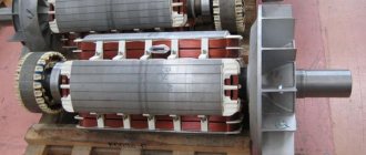
Powerful traction alternator - structure
Hello, connoisseurs of the world of electrical and electronics. If you often look at our website, you probably remember that quite recently we published quite a voluminous material about how a DC generator works and works. We have described its structure in detail, from the simplest laboratory prototypes to modern working units. Be sure to read it if you haven't already.
Today we will develop this topic and figure out what the operating principle of an alternating current generator is. Let's talk about the areas of its application, varieties and much more.
- Theoretical part Basic principles
- Alternating current
- Main working parts and their connections
- Car generators
What is an alternator and who invented it
An alternator is a specialized electrical unit that converts mechanical energy into electrical energy. The latter has a variable characteristic. The transformation itself is based on the mechanical rotation of a coil of wire inside a magnetic field.
Sectional demonstration of the device in question
For your information! Almost all modern generators use a rotating magnetic field rather than a coil to generate electricity.
As already mentioned, electric current is generated not only during the mechanical movement of the coil in the field of the magnet, but also when the field lines of the magnet, which is in rotational motion, intersect the turns of the coil. Thus, the emerging electrons begin their movement to the positive pole of the magnet, and the electric current itself flows from the positive pole to the negative one.
Current is induced in the conductor (coil). Its current repels the magnet when the coil frame approaches it, and repels it when the coil frame moves away. To put it simply, the current changes its orientation relative to the poles of the magnet each time. This causes such a phenomenon as alternating electric current.
Demonstration of the device using a simple magnet and a circuit
This device appeared back in 1832 thanks to the efforts of N. Tesla. It was then that the very first single-phase synchronous alternating current generator was created. The very first installations produced only direct current, and the variable characteristic generator in question could not find its practical application for some time. This did not last long, as people quickly realized that alternating current was much more practical to use than direct current.
You may be interested in Current through a capacitor
Note! The advantage of the new technology was that such electric current was easier to generate, and servicing the devices took much less time and resources than analogues operating on direct current.
It was thanks to alternating current and its generator that electrical appliances such as a radio, tape recorder and other later automatic and electrical installations were born, without which it is impossible to imagine the life of a modern person.
Using a graph to show AC and DC currents
Differences
Next, you will need to understand the main differences between alternating and direct current generators. They are as follows:
- The DC generator is equipped with a semi-ring to change the direction of the current.
- A diode bridge can be used to obtain a constant voltage.
- The need to use a regulator relay.
- There is also a difference depending on the speed of the drive mechanism.
For example, a car alternator cannot charge the battery when idling. In this mode, the machine engine rotates at a frequency of 800 rpm. Such revolutions are not enough to generate a charging current of sufficient power.
- The DC generator is equipped with a semi-ring to change the direction of the current.
- A diode bridge can be used to obtain a constant voltage.
- The need to use a regulator relay.
- There is also a difference depending on the speed of the drive mechanism. For example, a car generator cannot charge the battery when idling. In this mode, the machine engine rotates at a frequency of 800 rpm. Such revolutions are not enough to generate a charging current of sufficient power.
- The use of a delta connection is not used in DC generators. The reason lies in the fact that there is an abrupt change in phase EMF over time. In AC electric machines, such changes are smoother.
- Devices that generate electricity do not have much design difference. But constant-type generators require more human control. AC electric machines are more reliable and require less intervention, since they are often not equipped with complex electronic equipment for voltage regulation and control.
- Alternating voltage is generated at lower costs for copper windings, while the overall dimensions of such generators can be significantly smaller.
- To generate charging current, the generator must operate through a transmission mechanism. This is the only way to achieve instantaneous production of the desired value at low speeds.
The use of electrical machines that produce direct current is not advisable. This is due to the fact that they are less reliable. Much less expensive are devices for generating alternating voltage, which are equipped with rectifiers. Such a mechanism can operate at almost any speed while maintaining the required voltage and has overload protection. The dimensions of such a device will be much smaller, while the output power of the devices will be the same.
Alternator Specifications
The main technical characteristics of the alternating current generator: external, high-speed regulation and current-speed. The external characteristic is defined as the dependence of the voltage of the device on the current it generates. It is a constant and can be determined in the process of independent and independent excitation.
The speed control characteristic is most often calculated based on several values of the load current. The lowest excitation value is found when the load current is zero (the rotational speed is maximum).
The last current-speed characteristic is defined as one of the most important when choosing or creating a generator. Almost all new generators can independently limit their maximum current.
Note! This is done so that the rotor speed does not increase to the frequency of the induced starter.
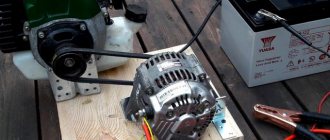
Simple induction generator for home and business use
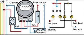
What generator voltage is considered normal?
To check the generator voltage, you need to start the engine and turn off the entire load. In this case, the multimeter should show 14.3 -15.5 Volts (see video at the end of the article). A deviation of 0.1 Volt in one direction or the other is allowed.
After this, it is necessary to connect consumers one by one and check the generator voltage.
Ideally, it should “drop” by about 0.2 Volts when you turn on each new load. In this case, the total U should not fall below the level of 12.8 Volts. Otherwise, the battery will be discharged.
Generator operating principle
It's time to look at the design of the alternator and the principle of its operation. It lies in the fact that a special system is used in the electrical installation, which, when operating, produces a high-power magnetic flux.
The basis is two cores made of electrical steel. The grooves of one core involve the placement of a winding, which is responsible for generating a flux of magnetic waves. The second is used to induce electromotive force.
Usually the core, which is located inside, is in a horizontal or vertical position and rotates in the corresponding orbits. It is called a rotor. The second core, called the stator, as its name implies, remains stationary. The smaller the distance between these elements, the more the magnetic flux inductance will increase. The following describes the purpose of the device and the operation of the alternator.
Consideration of the structure of an electric generator in practice
Start
The simplest and very first alternating current generator was developed by physicist Michael Faraday in 1831 and was called the Faraday Disk. The design of the first alternating current generator was very simple. It included the following elements:
- Two different polar magnets “N” and “S”.
- Copper wire frame with sides A, B, C, D.
- Rotation axes N and N1.
The principle of operation of the Faraday alternating current generator was that when the frame rotated, a current with a weak voltage was generated. This happens as follows:
- The wire frame rotates inside a constant magnetic field along the N and N 1 axis.
- When the position of the frame changes from vertical to horizontal, the effect of cutting the magnetic field occurs.
- At such moments, an electromotive force (EMF) arises.
- When passing one half-turn, the emf has a positive potential. Current flows from point A to point B.
- When returning to a vertical position, the EMF changes direction from point C to point D, which means the current potential also changes.
All alternators use a rotating magnetic field. When the position of the copper frame changes, there is also a moment of complete loss of voltage. It occurs when rotating slowly, for example, without a motor. During rapid rotation, the voltage remains unchanged.
Generator functions
When starting the engine, starting current is supplied to the starter from the battery. But the battery itself does not produce energy, but only accumulates it and then releases it. If you use only the battery to power all consumers, it will quickly discharge. A car generator produces electricity, charges the battery and powers the vehicle's on-board network while the engine is running (when it reaches a certain crankshaft speed). Car generator
The generator begins to produce electric current starting from the idle speed, however, it reaches optimal operating mode when the engine reaches 1600-1800 rpm or more.
False Self
The false self is an incorrect and unreal life strategy, something we are not. For example, if a person took some habits or interests from the outside and applied them to his life, calling them his own. But this may not suit his character or thinking. The false self leads to complexes, disorders, and resentments.
Generators and experience frustration with the false self. Since they are realized in life through the flow of energy, its absence leads to negative consequences - there is no desire or strength to do anything.
The energy flow becomes disrupted if the Generator:
The generator must respond, so telling what to do and what not to do will not work here. Ask and the child will answer. If you want him to be happy, drop your plans for him. It is important to skillfully handle his responses and ask the right questions, and not order him to do one way or another.
Read more about children of generators here.
Children's transcript here.
Alternating current generator device
The operation of any generator can be compared to an electric motor that operates in reverse mode, that is, it does not consume, but produces current. Based on the type of design, modern generators are divided into two types: compact and traditional. They have a common device, but differ in the layout of the housing, fan, rectifier assembly and drive pulley. Also, modern devices have three phases. Generator device
The generator consists of the following main elements:
- drive with pulley, bearings and shaft;
- rotor with field winding and slip rings;
- stator with core and winding;
- a housing consisting of two covers;
- voltage regulator;
- rectifier block or diode bridge;
- brush assembly.
Let's analyze each element of the device separately and in detail.
Frame
The housing contains all the main elements of the generator. It consists of two covers (front and back). The covers are connected to each other with bolts. For the manufacture of covers, light aluminum alloys are used, which are not magnetized and dissipate heat well. The covers have ventilation holes and mounting flanges.
The back cover contains a diode bridge and a brush holder with brushes. Also in the back cover there is an output contact through which current flows from the generator.
Drive unit
Rotation from the crankshaft is transmitted to the generator pulley and rotates the rotor. The pulley rotation speed is 2-3 times higher than the crankshaft speed. Torque from the engine is transmitted through a belt drive. Poly V-belts and V-belts can be used depending on the design. The poly V-belt is considered more versatile and modern.
It will be interesting➡ How to make a metal detector with your own hands
Rotor
On the rotor shaft there is an excitation winding, which creates a magnetic field and, in fact, is an ordinary electromagnet. The winding is located between two pole halves (cores) necessary to regulate and direct the magnetic field. Each half has six triangular projections called beaks. There are also two copper slip rings located on the rotor shaft. Sometimes they are made of steel or brass. The excitation winding receives power from the battery through slip rings. The winding contacts are soldered to the rings. Generator rotor
At the front end of the rotor shaft there is a drive pulley, and at the other end the fan impeller is mounted. There may be two of them. They are needed to cool the internal parts of the generator. There are also maintenance-free ball bearings at both ends of the rotor.
Stator
Structurally, the stator has the shape of a ring. This is the main part used to create alternating current from the magnetic field of the rotor. Consists of a winding and a core. In turn, the core consists of connected steel plates, in which 36 grooves are formed. Three windings are wound into the slots, which form a three-phase connection. There can be two winding connection schemes: “star” and “delta”. In a star circuit, the ends of each of the three windings are connected at one point. According to the “triangle” scheme, the ends of the windings are brought out separately.
What determines the shelf life of a battery?
Each manufacturer, after manufacturing a battery, sets a warranty period for its operation.
In addition to this parameter, there is an actual period that depends on many factors - timeliness of maintenance, compliance with operating rules, condition of electrical wiring and other points.
Due to the fact that battery maintenance conditions differ, the shelf life of the product also differs.
Car owners who use their car only in the warm season have the longest battery life. It's another matter when you need a car all year round, regardless of the outside temperature.
In such a situation, the battery life is reduced. This is also due to the fact that in the second case the driver can cover more kilometers.
The battery life is also affected by:
- Serviceability and correct operation of the generator and voltage regulator.
- Connecting additional equipment with a large rated current to the vehicle's electrical wiring.
- Operating mode. The batteries that last the least are those in taxis that travel a long distance throughout the year. In addition, such cars operate in frequent engine starting mode, which puts a load on the battery and generator. If the vehicle is actively used, the service life of the power source does not exceed 1.5 years.
Under normal operating conditions, when the car owner regularly checks the battery and carries out maintenance, the battery life is 4-5 years with a total mileage of 60-80 thousand kilometers during this period.
To avoid problems, it is advisable to periodically check the voltage of the generator and battery.
But the mentioned service life is not the highest, because with careful maintenance the battery can last up to eight years.
But you should know that sooner or later the battery will need to be replaced, because from the moment you start using it, the working plates gradually wear out. The more charge and discharge cycles a battery goes through, the faster it breaks down.
Practice shows that the key role is played by the generator, its serviceability and current voltage. That is why this aspect needs to be given key attention.
Classification and types of units
All electric generators can be classified according to operating criteria and the type of fuel from which electricity is generated. All generators are divided into single-phase (voltage output 220 Volts, frequency 50 Hz) and three-phase (380 Volts with a frequency of 50 Hz), as well as according to the operating principle and type of fuel that is converted into electricity. Generators can also be used in various fields, which determines their technical characteristics.
According to the operating principle
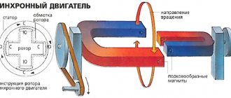
There are asynchronous and synchronous alternating current generators.
Synchronous
The synchronous type alternator has a main feature by which it can be identified at first glance. There is a winding wire on its rotor. It is necessary to stabilize the frequency between the stator and rotor. The EMF in such a device is created due to the intersection of the magnetic pole of the rotor and the stator winding.
A synchronous type alternator is equipped with rotors with several poles, the number of which is always a multiple of 2, for example, 2, 4, 6, 8. The alternator operates according to the following principle:
- After starting, the rotor creates a very weak magnetic field. The magnitude of the EMF increases as the shaft speed increases. For initial excitation, constant voltage from the battery or control unit is used.
- If the generator is powered by an internal combustion engine, the speed must first be stabilized to obtain a stable alternating voltage.
- After setting the required speed, the voltage is stabilized by the automatic regulation unit (AVR). Engine speed greatly affects the frequency of the alternating voltage at the output and its power. The optimal rotation speed is up to 3000 rpm. AVR stabilizes the voltage to this parameter, and in the event of a failure, significantly reduces the voltage. Otherwise, electric pumps can quickly lose power and overheat.
The operation of such a generator is highly dependent on the type of load. The induction type load greatly affects the demagnetization of the armature. This effect results in a large voltage loss.
With capacitive loads, the armature, on the contrary, is magnetized, which significantly increases the output voltage. The circuit of a synchronous type alternating current generator is shown below.
The synchronous alternator has one big advantage. Its output voltage is much higher (3-4 times) the nominal values. An increase is necessary if the device powers electric pumps, appliances and devices that require starting current. Such devices greatly increase the reactive loads on the general network, which a synchronous generator can cope with.
This generator also has disadvantages. The first is the high sensitivity to overload in the circuit. The reaction to the load is a short but quite powerful current on the rotor winding, which appears due to an increase in the current by the control unit itself. As a result, the winding burns out or heats up.
The second disadvantage is sparking. The simplest synchronous type generator has slip rings with brushes installed on the rotor. They are unsafe for use in industrial plants where flammable gases or liquids are present. For such cases, three machine synchronous generators are used. The design and operating principle of this type of alternator is very different. This generator consists of:
- Pre pathogen.
- Pathogen.
- The generator itself.
All these elements are installed on a common shaft. The work is carried out as follows:
- Permanent magnets installed on the shaft excite the winding of the synchronous generator before the exciter. Such a generator does not require a battery or an additional generator for excitation. Its work is based on the phenomenon of magnetic induction, which occurs when a permanent magnet rotates.
- The voltage that it generated is redirected to the exciter, or rather to its stator winding.
- The rotor winding is connected to a three-phase voltage rectifier.
- They are excited by the exciter stator.
Ultimately, the generator produces the nominal required voltage, which is regulated by the AVR unit. All operation of such a device is carried out in one housing, which is completely sealed.
Asynchronous
An asynchronous alternating current generator has a different device. Its rotor has no winding. For this reason, the principle of its operation is very different. During rotation, the rotor of such a generator advances the rotation of the magnetic fields that are created by the stator. The rotors of these devices have 2 types of winding: short-circuited and phase. The operating principle of asynchronous electric generators is as follows:
- A magnetic field is created on the auxiliary winding by the stator.
- After which the field is transmitted to the rotor and forms an EMF on the stator winding.
- The generated voltage is supplied to the control unit.
The main difference is the impossibility of adjusting the voltage at a set speed. Asynchronous generators are highly dependent on drive motors. Any loss of stability leads to a decrease in voltage and frequency of the current.
It will be interesting➡ What is a phase, how to determine phase and zero in electricity
The advantage of such devices is their low sensitivity to short circuits. Application - power supply of household appliances, welding equipment and electric pumps. When there is a reactive load, the AVR must increase the speed of the drive motor for a short period of time. At the same time, a step-down transformer included in the circuit protects other devices from overvoltage.
By engine fuel type
With the advent of generators, distance from the power grid no longer becomes an obstacle to using electrical appliances.
Gas generator
Gas is used as fuel, during combustion of which mechanical energy is generated, which is then replaced by electric current. Advantages of using a gas generator:
- Safety for the environment, because gas during combustion does not emit harmful elements, soot and toxic decomposition products;
- Economically, it is very profitable to burn cheap gas. Compared to gasoline, it will cost much less;
- Fuel supply is automatic. Gasoline and diesel fuel need to be added as needed, and the gas generator is usually connected to the gas supply system;
- Thanks to automation, the device comes into operation independently, but for this it must be located in a warm room.
Diesel generator
This category consists mainly of single-phase units with a capacity of 5 kW. 220 Volts and a frequency of 50 Hz are standard for household appliances, so a diesel unit copes well with a standard load. As you might guess, it requires diesel fuel to operate. Why you should choose a diesel electric generator:
- Relative cheapness of fuel;
- Automation that allows you to automatically start the generator when the power supply is interrupted;
- High level of fire safety;
- For a long period of time, a diesel unit can operate without failures;
- Impressive durability - some models are capable of working for a total of 4 years of continuous use.
Gasoline generator
Such devices are quite in demand as household equipment. Despite the fact that gasoline is more expensive than gas and diesel, such generators have many strengths:
- Small dimensions with high power;
- Easy to operate: most models can be started manually, and more powerful generators are equipped with a starter. The voltage is adjusted for a certain load using a special screw;
- In case of generator overload, protection is automatically triggered;
- Easy to maintain and repair;
- They do not make much noise during operation;
- Can be used both indoors and outdoors, but should be protected from moisture.
Types of devices
Despite the same structure, they are used in various types of devices and types of transport. A certain type of EG is used in various situations. There are main types of generator devices, which are classified by type of application:
- automobile;
- electric;
- inventory;
- diesel;
- synchronous;
- asynchronous;
- electrochemical.
The main purpose of a car battery is to rotate the crankshaft. A new type is used - a hybrid generator that acts as a starter. The basic principle of operation can be considered to be used to turn on the ignition, with I flowing through the slip rings and then to the alkaline part. Next, it moves to the excitation winding, a magnetic field is formed and the rotor is started, creating electromagnetic waves.
These waves penetrate the stator winding. Afterwards, an alternating current appears at the output of the winding. If the generator operates in self-excitation mode, then the rotation speed increases to the permissible value, and the alternating current is converted into direct current using a rectifier.
An electric generator performs the functions of a converter of mechanical energy into electrical energy. There can be many sources: water, steam, wind, internal combustion engines and other third-party forces that exert mechanical work on the generator rotor.
The inverter type of EG is very common. It is a self-contained power source that produces high-quality electrical energy. It is used almost everywhere and is a very reliable power source, in which there are no surges in U. Basic principle of operation:
- high-quality alternating current is generated, which is rectified using a diode bridge;
- direct current accumulates in batteries;
- The batteries are converted into stabilized alternating current using an inverter.
Another excellent and durable option is a diesel EG, which converts fuel energy into electrical energy. Fuel is burned and converted from chemical energy to thermal energy. The thermal energy is then converted into mechanical energy. Then a transformation occurs according to the old scheme: mechanical energy into electrical energy.
In a synchronous EG, the rotor acts as a permanent magnet with poles, the number of which ranges from 2 or more. However, a factor of 2 must be observed. During startup, the rotor generates a weak electromagnetic field, but as the rotation speed increases, a current appears in the field winding.
During this process, U appears and is supplied to a device that controls its value when the electromagnetic field changes. Synchronous type generators have proven themselves to be excellent due to their stably produced U.
However, they have a significant drawback - a possible overcurrent, as well as the presence of a brush assembly, which sometimes has to be serviced.
The principle of operation of an asynchronous type EG is based on constant being in the “braking with a moving part” mode, rotating in advance. The rotor can be either phase or squirrel-cage. An auxiliary magnetic field is created by the field winding and continues to be induced in the rotor. The frequency of the current and U depend on the number of revolutions.
A very interesting source of electricity is the electrochemical generator. Electrical energy is obtained from hydrogen. It is a chemical source of current, as a reaction of this type of interaction between oxygen and hydrogen molecules takes place.
However, this source is quite dangerous. After all, hydrogen can explode in large quantities, and oxygen acts as a catalyst. At the source of the hydrogen explosion, a significant combustion will occur, as oxygen will intensify the combustion.
In addition, when using EG, it is necessary to use devices in conjunction with them that regulate the parameters U and frequency. The principle of operation of the device is to maintain constant values of U and other parameters of electricity for high-quality power supply to consumers. The regulator also protects the generator from overloads and emergency mode. If an emergency occurs with a regulator, the generator will not start and will remain off. This is possible in case of a short circuit in the consumer circuit. These devices pick up U, frequency and I, as well as F.
It will be interesting➡ How to connect a switch with one key: rules and connection diagrams
A few words about electrolyte
One of the main indicators by which you can judge the health of a battery is the electrolyte level. The voltage of the power supply depends on it under different operating modes.
In the process of discharging the battery, acid is consumed, the share of which in the total volume of liquid is a third (35-36%).
The result is a decrease in the density of the liquid. When the battery is charged, the reverse process occurs.
In such a situation, water is consumed, and acid, on the contrary, is formed. As a result, the density of the electrolyte increases.
In the normal state, when the battery voltage is 12.7 V, the density is 1.27 g/cc. Moreover, all parameters directly depend on each other.
Application of alternating current generators in practice
Industrial production of powerful generators
Such generators are used in almost all areas of human activity where electrical energy is required. Moreover, the principle of its extraction differs only in the method of driving the device shaft. This is how hydro, heat and even nuclear power plants work.
These stations power public networks via wires, to which the end consumer, that is, all of us, connects. However, there are many objects to which it is impossible to deliver electrical energy in this way, for example, transport, construction sites far from power lines, very distant villages, shifts, drilling rigs, etc.
This means only one thing - you need your own generator and engine to drive it. Let's look at several small and common devices in our lives.
Synchronous generators are devices designed to produce alternating current. You can find such devices at various stations:
- atomic;
- thermal;
- hydroelectric power plants.
The units are also actively used in transport systems. They are used in various cars and ship systems. A synchronous generator is capable of operating both in autonomous mode, separately from the electrical network, and simultaneously with it. In this case, it is possible to connect several units at once.
The advantage of stations generating alternating current is the ability to provide a dedicated space with electricity. Convenient if the object is located far from the central network. Therefore, the units are in demand among owners of farms in settlements remote from the city.
Main Applications
Depending on where the electric generator is used, its technical characteristics are determined. Mainly, the relationship of the generator to a certain category in the field of application determines its power. The following types of equipment are divided into areas of operation:
- Household. They have a power from 0.7 to 25 kW. Gasoline and diesel generators typically fall into this category. They are used to supply power to household electrical appliances and low-power equipment, very often on construction sites. Suitable as a portable source of electricity when going outdoors;
- Professional. Can be used as a permanent source of electricity in municipal institutions and small industrial enterprises. Its power does not exceed 100 kW;
- Industrial. They can be used in large factories and factories where high-power equipment is required. Such devices have a power of more than 100 kW, have considerable dimensions and are difficult to maintain for an untrained person.
Liquid fuel generator
Gasoline generator
The design of a gasoline alternating current generator, just like a diesel one, is not much different from the one installed in your car, with the exception of the nuance that it will produce alternating current, as expected.
One of the features that can be highlighted is that the rotor of the unit must always rotate at the same speed, since when there are changes, the electricity generation becomes worse. This is a significant drawback of such devices - a similar effect occurs when parts wear out.
Interesting to know! If you connect a load to the generator that is lower than the operating load, then it will not use its full power, wasting part of the liquid fuel.
Generator control panel
There is a large selection of similar units on the market, designed for different capacities. They are very popular due to their mobility. At the same time, the instructions for use are extremely simple - fill in the fuel with your own hands, start the engine by turning the key and connect...
We'll probably end here. We have analyzed the purpose and general structure of these devices as simply as possible. We hope that the alternating current generator and the principle of its operation have become a little closer to you, and with our help you will want to immerse yourself in the fascinating world of electrical engineering.
Car generators
Electric generator for car
Someone might immediately say: “How? This is a DC generator!” Yes, indeed, it is so, but what makes it so is only the presence of a rectifier, which makes this very current constant. The basic principle of operation is no different - the same rotor, the same electromagnet, etc.
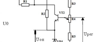
Schematic diagram of a car generator
This device operates in such a way that, regardless of the shaft rotation speed, it produces a voltage of 12V, which is provided by the regulator through which the field winding is powered. The excitation winding starts, powered by a car battery, the rotor of the unit is driven by the car engine through a pulley, after which an EMF begins to be induced.
Several diodes are used to rectify three-phase current.
Main working parts and their connections
If you read the previous material, you probably remember that the frame in the simplest circuit was connected to a collector divided into insulated contact plates, which, in turn, was connected to brushes sliding along it, through which the external circuit was connected.
Due to the fact that the collector plates are constantly changing brushes, there is no change in the direction of the current - it simply pulsates, moving in one direction, that is, the collector is a rectifier.
Design and principle of operation of an alternating current generator
- For alternating current such a device is not needed, so it is replaced by slip rings to which the ends of the frame are attached. The entire structure rotates together around a central axis. Brushes are adjacent to the rings, which also slide along them, ensuring constant contact.
- As in the case of direct current, the EMF arising in different parts of the frame will be summed up, forming the resulting value of this parameter. In this case, an electric current will flow in the external circuit connected through the brushes (if a load resistor RH is connected to it).
- In the example above, “T” equals a full turn of the frame. From here we can draw a logical conclusion that the frequency of the current generated by the generator directly depends on the speed of rotation of the armature (frame), or in other words, the rotor, per second. However, this only applies to such a simple generator.
Three-phase alternating current generators and their design
We recommend reading: Why are capacitors needed in radio electronics and what types of them are there?
If you increase the number of pole pairs, then in the generator the number of total current changes per one revolution of the armature will increase proportionally, and its frequency will be measured differently, according to the formula: f = np, where f is the frequency, n is the number of revolutions per second, p – number of pairs of magnetic poles of the device.
- As we wrote above, the flow of alternating current is graphically represented by a sinusoid, therefore such a current is also called sinusoidal. We can immediately identify the main conditions that determine the constancy of the characteristics of such a current - this is the uniformity of the magnetic field (its constant value) and the constant speed of rotation of the armature in which it is induced.
- To make the device powerful enough, it uses electric magnets. The rotor winding, in which the EMF is induced, in operating units is also not a frame, as we showed in the diagrams above. A very large number of conductors are used, which are connected to each other according to a certain pattern
Interesting to know! The formation of EMF occurs not only when the conductor is displaced relative to the magnetic field, but also vice versa, when the field itself moves relative to the conductor, which is actively used by designers of electric motors and generators.
- This property allows you to place the winding in which the EMF is induced, not only on the rotating central part of the device, but also on the stationary part. In this case, the magnet, that is, the poles, is set in motion.
Synchronous electric current generator and the principle of operation of this device
- With this structure, the external winding of the generator, that is, the power circuit, does not require any moving parts (rings and brushes) - the connection is made rigid, often bolted.
- Yes, but you can reasonably object that these same elements will need to be installed on the excitation winding. This is true, however, the current flowing here will be much less than the final power of the generator, which greatly simplifies the organization of current supply. The elements will be small in size and weight and very reliable, which makes this particular design the most popular, especially for powerful units, for example, traction units installed on diesel locomotives.
- If we are talking about low-power generators, where current collection does not present any difficulties, therefore the “classical” circuit is often used, with a rotating armature winding and a stationary magnet (inductor).
Advice! By the way, the stationary part of an alternator is called a stator, since it is static, and the rotating part is called a rotor.
It is easier to rotate the central part