If power must be supplied to both single-phase and three-phase devices (tools, machines), then a three-phase generator is needed. It is capable of powering equipment of different phases, both 220 Volts and 380 Volts - that’s what a three-phase generator means. Thus, in the absence of current in the stationary network, you can turn on both a 220V hammer drill or a 380V concrete mixer, but not simultaneously, but alternately. A three-phase generator is a necessary purchase for both home use and industrial sites.
Homemade generator, is it possible?
Although the three-phase power plant is a very complex unit, you can assemble it yourself by studying the principle of operation of the generator and having available elements and parts. For this, an asynchronous electric motor is used.
The principle of operation is based on the familiar dynamo - force the rotor to rotate forcibly. How does a three-phase generator work? Based on an asynchronous motor. In order for this motor, not connected to the network, to work as a source of electricity, it is necessary to transmit torque to its armature. Torque arises from any mechanical energy.
The best way to make a three-phase generator is to use an internal combustion engine. Moreover, you can create not only a gasoline generator, but an economical gas or powerful diesel one. To connect to the engine, a shock-absorbing coupling is used so that the rotor rotates smoothly rather than jerkily.
Even more - having understood in detail what a three-phase generator is, you will understand that mechanical energy can be obtained not only from the internal combustion engine, but from completely free media. This means that you can use the energy of a river or wind (if natural conditions are favorable). In this case, you need to assemble and install a turbine, wind or water. It turns out to be an excellent opportunity to save on paying for electricity received from a stationary network.
In some localities in Ukraine, horses are even used to rotate the rotor. This method of building an electric generator with your own hands is popular among certain religious communities that fundamentally do not use stationary electricity. Several harnessed horses rotate the anchor, creating the necessary mechanical energy. It turns out cheap electricity from live horsepower.
Story
Electrical machines generating alternating current have been known in a simple form since the discovery of magnetic induction of electric current. Early machines were designed by Michael Faraday and Hippolyte Pixie.
Faraday developed a "rotating rectangle" whose action was multipolar
- each active conductor was passed sequentially through an area where the magnetic field was in opposite directions. The first public demonstration of the most powerful "alternator system" took place in 1886. The large two-phase alternating current generator was built by British electrician James Edward Henry Gordon in 1882. Lord Kelvin and Sebastian Ferranti also developed an early alternator that produced alternating current with a frequency between 100 and 300 hertz. In 1891, Nikola Tesla patented a practical "high frequency" alternator (which operated at a frequency of about 15,000 hertz). After 1891, multiphase alternators were invented. A three-phase current generator with a three-wire load was proposed by the Russian engineer Dolivo-Dobrovolsky, who in 1903 built the world's first industrial three-phase power plant, which powered the Novorossiysk grain elevator.
Tags: beat, sconce, view, excitation, choice, switch, generator, engine, house, , capacity, grounding, insulation, like, computer, capacitor, , magnet, power, load, voltage, neutral, nominal, lighting, soldering iron , skew, variable, periodicity, constant, rule, principle, wire, manufacturer, start, vacuum cleaner, , work, size, calculation, regulator, relay, relay regulator, switch, row, light, network, system, connection, means, term , stabilizer, circuit, ten, type, current, transformer, triangle, three-phase, , phase, electricity, armature
How does a homemade 380 Volt generator work?
When the rotor rotates, a magnetic field appears in the stator, generating an emf. The drive is designed in such a way that if you connect a capacitor to the ends of the windings, current begins to flow through the turns. The capacitance of the capacitor bank must be above the critical rating for the generator to be suitable for resistive loads and to produce symmetrical three-phase voltages.
In addition to this indicator, the power of the electric generator is also affected by the engine that creates the torque, its design and power.
To produce electricity of 380 Volts with a standard frequency of 50 Hz, the rotation speed of the drive armature must be maintained at a certain level. Magnetic force lines will appear only if the speed is higher than the asynchronous component by the slip coefficient S (equal to 2÷10 percent) and corresponds to the level of the synchronous frequency. Otherwise, it is impossible to achieve the correct current sinusoid, and its curvature (frequency jumps) is unacceptable if we connect devices equipped with electric motors (drills, rotary hammers, grinders, saws) to a 380 Volt power station. If there is no motor, but only a heating element or an incandescent lamp, then the frequency value and the current sinusoid are not so important.
There is also the option of using 220 Volt generators to run the electric motor. In this case, we get a homemade three-phase generator from a single-phase one. The transmission of torque goes to the armature of an asynchronous three-phase drive, resulting in a three-phase network.
Advantages and disadvantages
Like everything material, three-phase current has its pros and cons. The positive aspects of using systems with three or four wires include:
- efficiency. To transmit electricity over long distances, cores made of non-ferrous metals with low resistivity are used. The voltage is divided proportionally to the number of cables. By distributing loads, engineers can reduce the number of wires and their cross-section, which, given the cost of rare materials, provides noticeable savings;
- efficiency. The power parameters of three-phase transformers are an order of magnitude higher than single-phase transformers with smaller magnetic core sizes;
- simplicity. When consumers are simultaneously connected to a three-phase system, an additional electromagnetic field is generated. The phase shift effect has made it possible to create simple and reliable brushless electric motors, the rotor of which is made according to the principle of a conventional blank and is mounted on ball bearings. Asynchronous electric drives with a squirrel-cage rotor are widely used as power units. The main advantage of such motors is the ability to change the direction of rotation of the axis by switching to different phase wires;
- variability. In circuits with several phases, it is possible to obtain different voltages. The user will be able to change the power of the heater or servo drive by switching from one cable to another;
- reducing the stroboscopic effect. It is achieved by independently connecting different lamps to individual phases.
Along with its advantages, three-phase current has its disadvantages. They include:
- connection difficulty. To connect a three-phase network to a private or industrial building, you must obtain special permission and technical specifications from the local energy sales company. This event is quite expensive and troublesome. Even if all conditions are met, a positive result is not always guaranteed;
- application of enhanced security systems. The three-phase network supplies a voltage of 380 V, so additional devices for protection against electric shock and short circuits are required, which can lead to fire. In such cases, another three-pole circuit breaker with higher ratings is installed at the input. It will help avoid fire in the event of a short circuit;
- the need to install auxiliary modules to limit overvoltage in the distribution board. It is necessary in case the neutral cable breaks, which will lead to an increase in voltage in one of the phases.
The transition to three-phase current is advisable for owners of premises whose area is more than 100 square meters. meters. This applies to private homes and industrial buildings. This connection scheme will allow you to redistribute the load evenly across all consumers and avoid power surges.
What kind of asynchronous motor is needed: characteristics of the rotor and stator
The asynchronous three-phase drive is the main basis for the alternator. Very often, such motors are written off at enterprises, so you can find one at a low price or for free. Mandatory conditions for choosing what kind of rotor and stator it has:
- The rotor of such an engine can be phase or squirrel-cage;
- The stator has three separate copper windings. The connection of the turns to each other is allowed in the “triangle” or “star” type.
The design and operating principle of such a drive is that the rotor (armature) is a rotating element, the stator is stationary. They both have insulated steel plates as their base. On these plates there are grooves in which the turns of the winding go.
In the stator, the outputs of the turns must be connected to the terminal box and jumpers must be installed for the connection. The power cable is also installed here.
Identical voltages are connected to each stator phase, shifted by an angle that is approximately a third of a circle. These synchronous connections are responsible for generating current in the stator turns.
In the rotor, the connection depends on the features of its structure: phase or short-circuited.
- Slip rotor. Such a rotor has winding turns similar to those of the stator. Their outputs must be mounted on rings that make contact and come into contact with the trigger circuit and pressure brushes. The design is not simple, you need to tinker with it. In addition, you need to constantly monitor the rotation speed and see if the contact rings have opened or the pressure brushes have come off. Therefore, it is better to choose a squirrel-cage type rotor. Or make a squirrel-cage armature from a phase rotor. To do this, the ends of the winding are not connected to the rings, but combined with each other - shortened.
- Squirrel-cage rotor. As we have already said, it is more convenient for creating a generator yourself, since, unlike a synchronous generator, its circuit is simple. The jumper rings are connected and short-circuited at their ends; there are no movable pressing brush contacts. It turns out everything is very simple and reliable, so we recommend choosing this kind of anchor for your homemade project.
Device
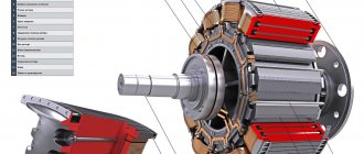
The design of synchronous generators uses two main working parts - a rotating rotor and a stationary stator. Permanent magnets or field windings are located on the rotor shaft. Magnets have a toothed shape, with opposite poles.
Brushless generators.
The stator windings are placed in such a way that their cores coincide with the protrusions of the magnetic poles of the rotor, or with the cores of the rotor coils. The number of magnet teeth usually does not exceed 6. With this design, the generated current is removed directly from the stator windings. In other words, the stator acts as an armature.
In principle, permanent magnets can be placed on the stator, and the working windings, in which the EMF will be induced, can be placed on the rotor. This will not change the performance of the generator, but it will require rings and brushes to relieve voltage from the armature windings, and this is most often not rational.
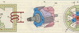
A schematic representation of a brushless generator without field windings is shown in Fig. 1.
Rice. 1. Model of a generator with a magnetic rotor
Explanation:
- device diagram;
- diagram of the location of the magnetic poles on the anchor. Here, the letters NS denote a coaxial magnet with poles, and the letter R denotes the steel magnetic core of the rotor in the form of claw-shaped tips.
- cutaway model of the generator. The terminals of the stator phase windings are connected in a star.
What are the effects of connection diagrams?
The layout of a three-phase generator in terms of the placement of windings on the motor stator affects the subsequent operation of the device and determines its technical characteristics.
- Wiring diagram for star connection. This is the standard type of coil connection and is very popular. It is the most practical when connecting a capacitor bank. Its connection can be done:
- To two windings. As a result of this scheme, asynchronous generators provide power to single-phase devices (two groups) and three-phase devices (one line). The switch keys for the working and starting capacitors are separate.
- To one winding (according to the same circuit). We get one single-phase line. And one three-phase.
Functional differences of the unit
In order for the device to work smoothly for many years, you need to familiarize yourself in advance with the operating principle of a synchronous generator. To evaluate the functionality of the unit, the same characteristics are used as for devices with direct current. The main differences concern only certain operating conditions.
The main characteristics of a synchronous unit include the following facts:
- A decrease in voltage readings is observed in the active and inductive resistance of the device windings. This figure may increase as the load on the unit itself increases.
- Idling. The EMF of the device largely depends on the excitation currents, which at the same time indicates the magnetization of the special circuits of the machine.
- Adjustment parameters of a three-phase generator. Manufacturers note the fact that excitation currents depend on the load. During active operation of a synchronous generator, it is necessary to constantly maintain the optimal voltage at the terminals. It is quite simple to comply with this requirement; the main thing is to regulate the EMF of the unit. The master can change the excitation current automatically. With an active-capacitive load, it is necessary to reduce the excitation current to continuously maintain a constant voltage.
What engine characteristics still need to be paid attention to?
For reliable and stable operation of a self-made generator, certain technical characteristics of the engine are important. They are indicated on a sticker or in your passport (if you have one). Important points are:
- Protection class (IP designation). The lower the number, the better the drive housing is protected from the penetration of dust and moisture.
- Power.
- Number of revolutions.
- Diagram of the combination of turns of the stator winding.
- Maximum load currents.
- Efficiency.
- Starting current (phi coefficient).
All this should be clarified, and if the motor is old and has been used for many years, then it needs to be tested with a voltmeter, ammeter and “ringed” for working condition.
The best three-phase generators with autostart
Hyundai HHY 10000FE-3 ATS
Gasoline generator designed to create a main or backup source of electricity in emergency situations.
Based on a four-stroke air-cooled Hyundai IC460 engine. The model is equipped with electric, manual and automatic start.
The front panel is equipped with a multifunction display . The main operating parameters are reflected in real time.
To find out when maintenance is needed, just check the hour meter.
Characteristics:
- engine capacity - 460 cubic meters. cm, power - 18 l. With.;
- tank volume - 25 l;
- active power - 7.5 kW, max. — 8 kW, full — 9.38 kW;
- noise level - 74 dB;
- there is a muffler, overload protection, a voltmeter, an hour meter;
- sockets - 1 for 220 V, 1 for 380 V, 1 for 12 V;
- dimensions - 75x62x59 cm;
- weight - 89.5 kg.
Advantages:
- stable voltage;
- quiet operation
- fast start;
- reliable automatic start;
- convenient operation;
- display of exact parameters;
- emergency shutdown system;
- spacious fuel tank.
Flaws:
- No.
Daewoo Power Products GDA 8500E-3
Gasoline generator based on the Daewoo series 440 engine system with automatic start . It will act as a reliable power plant for private houses and small plots.
Thanks to the serial number on the motor, the user can verify the originality of the device.
An additional advantage will be the AVR system, which helps maintain voltage at a given level . Effective protection will prevent overheating or accidental short-circuiting of the unit, as well as connected devices.
Characteristics:
- engine capacity - 445 cubic meters. cm, power - 18 l. With.;
- tank volume - 30 l;
- active power - 7 kW, max. — 7.5 kW, full — 9.3 kW;
- there are wheels, a muffler, a voltmeter, an hour meter;
- sockets - 1 for 220 V, 1 for 380 V;
- dimensions - 68x54x52 cm;
- weight - 94.1 kg.
Advantages:
- automatic start block;
- convenient transportation;
- stable output voltage;
- oil level sensor;
- automatic shutdown;
- spacious fuel tank;
- easy start of the entire system.
Flaws:
- No.
Hyundai HY12000LE-3
This gasoline generator will become a reliable and powerful unit for creating a backup source of electricity . Excellent for providing electricity to construction sites, private and country houses, and large enterprises.
Due to its high and stable output power, it is used to connect equipment with high starting points.
Equipped with automatic start, remote control.
The four-stroke, two-cylinder, air-cooled Hyundai IC680 engine has proven itself in extreme operating conditions.
Characteristics:
- engine capacity - 678 cubic meters. cm, power - 22 l. With.;
- tank volume - 28 l;
- active power - 9 kW, max. — 10 kW;
- noise level - 72 dB;
- there are wheels, a muffler, a voltmeter, an hour meter;
- sockets - 2 for 220 V, 1 for 380 V, 1 for 12 V;
- dimensions - 106x73x84 cm;
- weight - 170 kg.
Advantages:
- many sockets;
- overload protection system;
- LED display showing accurate indicators;
- anti-vibration system;
- economical fuel consumption;
- fuel and oil level indicators;
- operation of the remote control at a distance of 50 m from the common station;
- brushed three-phase alternator;
- comfortable wheels.
Flaws:
- No.
How to calculate generator power
In order for the operation of a homemade power plant to be stable, it is necessary that its rated voltage and power be the same in generator and electric motor modes. Before choosing a capacitor bank, you need to consider:
- Reactive power Q. It is equal to 2n*f*C*U2, where C is the capacitance of the capacitor. Hence, the capacitance C we need will be equal to Q/2n*f *U2.
- Operating mode. To prevent winding overload and overheating during idle mode, the capacitor elements are connected in a stepwise manner, in accordance with the load.
Our recommended brand of starting capacitors is K78-17, with a voltage of 400 Volts and higher. Metal-paper elements with similar characteristics are also allowed. They are connected in parallel.
We do not recommend using electrolyte batteries for alternating current. A direct current generator can operate on them, but with an alternating current, the elements of the electrolytic capacitor will quickly fail.
Principle of operation
The operation of a three-phase generator is based on Faraday's law - the law of electromagnetic induction, which states that an electromotive force will necessarily be induced in a rotating rectangular frame, which is installed between two magnets. The caveat is that the magnets will create a rotating magnetic field. The direction of rotation of both the frame and the magnetic field must coincide. But an electromotive force will also arise if the frame remains stationary and the magnet rotates inside it.
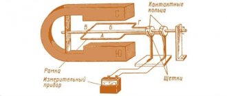
To understand how the generator works, pay attention to the figure below. This is the simplest way it works.
Here you can clearly see magnets with different poles, a frame, a shaft and slip rings, with the help of which current is drained.
Of course, this is just a diagram, although laboratory generators were created this way. In practice, ordinary magnets are replaced by electromagnets. The latter are copper windings or inductors. When an electric current passes through them, the necessary magnetic field is formed. Such generators are installed in all cars (this is just an example); to start them, a battery is installed under the hood, that is, a direct current source. Some generator models are started using the principle of self-excitation or using low-power generators.
Alternator circuit
Varieties
The classification is based on the principle of operation, therefore these AC units are divided into two classes:
- Asynchronous. These are the most reliable generators, small in size and weight, simple in design. They cope well with overloads and short circuits. However, it is necessary to take into account that this type will immediately fail if it is subject to a large overload. For example, the starting current of electrical equipment. Therefore, it is worth taking this fact into account, for which you will have to purchase a generator with a power three or four times greater than the power consumed by the equipment at startup.
- Synchronous. But this type easily copes with short-term loads. Such a generator can withstand an overload of five or six times. True, it does not differ in high reliability compared to asynchronous options; moreover, it is large in size and weight.
Safety Tips and Recommendations
Three-phase voltage of 380 Volt is a great danger of human injury and death. Therefore, safe operation of a homemade product is the most important requirement. To guarantee it, the following conditions must be met:
- Management of a single electrical panel, which includes:
- Measuring instruments: voltmeter (with a maximum of not less than 500 Volts), ammeter and frequency meter.
- Switches for interaction of loads (three keys). One of them turns on the power directly to the consumer, and the other two are responsible for connecting the capacitor elements.
- The protection system is a circuit breaker that trips in the event of a short circuit or power overload. This also includes a protective shutdown device, which should trip if a phase breaks through to the housing.
- Reliable grounding to the earth circuit.
- AVR system. For ease of operation and increased security, we also recommend using automatic reserve entry. It is relevant if you need backup power as a generator. Then it will be able to turn on independently when the current in the stationary network disappears, and also automatically turn off when it appears. ATS is created by installing a changeover switch that uses all three phases.
Design of a synchronous alternating current generator, operating principle
- single-phase current is supplied to consumers through one conductor, three-phase - through three;
- to complete the network, a neutral cable is required, therefore in circuits with one phase there are two of them, and in three - four;
- power increases with increasing number of phases;
- simplicity of network design;
- voltage drops appear in a single-phase circuit with an increase in the number of electricity consumers;
- When one wire is disconnected in a three-phase system, the current continues to flow in the remaining two wires. In single-phase, the voltage disappears completely.
Operating tips: what difficulties may arise
A common problem with generator operation is power overload. This causes intense heating of the winding and breakdown of the insulation. As a result, the generator breaks down. Occurs due to:
We have already discussed the rules for selecting containers and calculations above. And regarding the problem of power overload in a three-phase generator, it is necessary to note some more nuances when connecting single-phase consumers:
- Consumers with a voltage of 220 Volts can only be connected to one third of the total power (for example, if a generator produces 6 kW, then this is only for 380 Volt devices, and for single-phase devices it will be only 2 kW, no more). Otherwise, there will be an overload.
- If your generator has two single-phase lines, then together the power through them will be 2/3 of the total power. That is, 6 kW is 4 kW for single-phase, 2 kW for each phase. Moreover, when using phases at the same time, make sure that the load does not differ from the power by up to 10%, otherwise the phenomenon of “phase imbalance” will occur and no current will flow.
When working, it is important to monitor the AC frequency indicator. If you have not built a frequency meter into the common electrical panel, then at idle the output voltage is 4–6 percent higher than 380 Volts (or 220 when connecting single-phase ones).
Theoretical part
The basic principle of operation of an alternator
Let's start with the most basic - alternating current differs from direct current in that it changes its direction of movement with some frequency. It also changes the value, which we will talk about in more detail later.
After a certain period of time, which we will call “T”, the values of the current parameters are repeated, which can be depicted on the graph as a sinusoid - a wavy line passing with the same amplitude through the central line.
Basic principles
So, the purpose and design of alternating current generators, previously called an alternator, is to convert kinetic energy, that is, mechanical, into electrical energy. The vast majority of modern generators use a rotating magnetic field.
- Such devices operate due to electromagnetic induction, when when a coil of conductive material (usually copper wire) rotates in a magnetic field, an electromotive force (EMF) arises in it.
- The current begins to form at the moment when the conductors begin to cross the magnetic lines of the force field.
The structure of the simplest electromagnetic generator
Moreover, the peak value of the EMF in the conductor is achieved when it passes the main poles of the magnetic field. At those moments when they slide along the lines of force, induction does not occur and the emf drops to zero. Take a look at any of the diagrams presented - the first state will be observed when the frame takes a vertical position, and the second - when it is horizontal.
Alternating current generator - how it works
- To better understand the ongoing processes, you need to remember the rule of the right hand, studied by everyone in school, but few remember. Its essence lies in the fact that if you position your right hand so that the magnetic field lines enter it from the palm, the thumb moved to the side will indicate the direction of movement of the conductor, and the remaining fingers will indicate the direction of the EMF arising in it.
- Take a look at the diagram above, position "a". At this moment, the emf in the frame is zero. The arrows show the direction of its movement - part of frame A moves towards the north pole of the magnet, and B - towards the south, reaching which the EMF will be maximum. Applying the right-hand rule described above, we see that the current begins to flow in part “B” towards us, and in part “A” - away from us.
- The frame rotates further and the current in the circuit begins to fall until the frame again takes a horizontal position (c).
- Further rotation leads to the fact that the current begins to flow in the opposite direction, since parts of the frame have swapped places when compared with the initial position.
After half a revolution, everything will return to its original state and the cycle will repeat again. As a result, we found that during the complete revolution of the frame, the current increased twice to a maximum and dropped to zero, and once changed its direction relative to the initial movement.
Alternating current
The current frequency was named in his honor
It is generally accepted that the duration of the circulation period is 1 second, and the number of periods “T” is the frequency of the electric current. In standard electrical networks in Russia and Europe, in one second the current changes its direction 50 times - 50 periods per second.
In electronics, one such period is designated by a special unit, named after the German physicist G. Hertz. That is, in the given example of Russian networks, the current frequency is 50 hertz.
In general, alternating current has found very wide application in electronics due to the fact that: the magnitude of its voltage is very easy to change using transformers that do not have moving parts; it can always be converted to direct current; the design of such generators is much more reliable and simpler than for generating direct current.
The most powerful generators installed at the Pushkinskaya hydroelectric station
Components
The operating principle and design of a synchronous generator differ in that this unit can be used as a motor and a generator. Its functionality allows you to quickly move from the engine schedule to the generator schedule - this largely depends on the action of the braking or rotating force of the equipment. This operating principle is highly valued among qualified specialists. It is worth noting that in the engine graph, electrical energy enters the system and mechanical energy exits.
The synchronous generator device includes the following elements:
- High quality winding of the device.
- Rotor or inductor (rotating or moving type). This element is supplied with an excitation winding.
- Several varieties of powerful cables that can withstand heavy loads.
- Convenient stator coil switch.
- Special straightener.
- High quality rotary reel.
- A dedicated DC power supply whose operation can be controlled by the user.
The three-phase generator is part of the alternating current circuit of nonlinear resistances.
DIY asynchronous generator
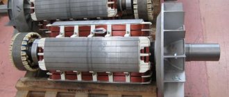
Let’s make a reservation right away: we are not talking about making a generator from scratch, but about converting an asynchronous motor into an alternator. Some craftsmen use a ready-made stator from a motor and experiment with the rotor. The idea is to use neodymium magnets to make the rotor poles. A workpiece with glued magnets might look something like this (see Fig. 6):
Rice. 6. Blank with glued magnets
You glue magnets onto a specially machined workpiece mounted on the electric motor shaft, observing their polarity and shift angle. This will require at least 128 magnets.
The finished structure must be adjusted to the stator and at the same time ensure a minimum gap between the teeth and the magnetic poles of the manufactured rotor. Since the magnets are flat, you will have to grind or sharpen them, while constantly cooling the structure, since neodymium loses its magnetic properties at high temperatures. If you do everything correctly, the generator will work.
The problem is that it is very difficult to make an ideal rotor in artisanal conditions. But if you have a lathe and are willing to spend a few weeks making adjustments and modifications, you can experiment.
I propose a more practical option - turning an asynchronous motor into a generator (see video below). To do this, you will need an electric motor with suitable power and an acceptable rotor speed. The engine power must be at least 50% higher than the required alternator power. If you have such an electric motor at your disposal, start processing. Otherwise, it is better to buy a ready-made generator.
For recycling you will need 3 capacitors of the KBG-MN, MBGO, MBGT brands (you can take other brands, but not electrolytic ones). Select capacitors for a voltage of at least 600 V (for a three-phase motor). The reactive power of the generator Q is related to the capacitor capacity by the following dependence: Q = 0.314·U2·C·10-6.
As the load increases, the reactive power increases, which means that in order to maintain a stable voltage U it is necessary to increase the capacitance of the capacitors, adding new capacitances through switching.
Video: making an asynchronous generator from a single-phase motor - Part 1 https://www.youtube.com/watch?v=ZQO5S9F72CQ
Part 2 https://www.youtube.com/watch?v=nDCdADUZghs
Part 3 https://www.youtube.com/watch?v=6M_w1b2xyM8
Part 4 https://www.youtube.com/watch?v=CONHg7p-IYE
Part 5 https://www.youtube.com/watch?v=z2YSqVh1vM8
Part 6 https://www.youtube.com/watch?v=FNU83kOeSbA
To simplify the selection of capacitors, use the table:
Table 1
| Alternator power (kW-A) | Capacitor capacity (uF) at idle | Capacitor capacity (uF) at average load | Capacitor capacity (µF) at full load |
| 2 | 28 | 36 | 60 |
| 3,5 | 45 | 56 | 100 |
| 5 | 60 | 75 | 138 |
In practice, the average value is usually chosen, assuming that the load will not be maximum.
Having selected the parameters of the capacitors, connect them to the terminals of the stator windings as shown in the diagram (Fig. 7). The generator is ready.
Rice. 7. Capacitor connection diagram
UPD: Connecting the boiler to the generator.
Often a generator is purchased to be used in winter to power the heating system boiler. There are some peculiarities here.
For imported phase-dependent boilers, it is important that the power system has a solidly grounded neutral, i.e. neutral and ground are connected together, and when connecting, the polarity is observed (phase-zero)
In the case of a portable generator, which is discussed in the article, there is neither zero nor phase. They must be made artificially - one output of the generator will be a phase (L2), and the second (N2) will be placed on the ground, i.e. ground.
In addition, as is known, boilers are very sensitive to the voltage form. And at the output of a conventional generator, the sine wave is “dirty”; if necessary, I will take an oscillogram. First of all, this happens because... The alternator that generates electricity is brushed, and because of the brushes sparking, failures, and similar unpleasant things occur.
It is because of this that Off-line and Smart UPS are not suitable for boilers. There at the output there is a quasi-sine with a bunch of harmonics, the oscillograms can be viewed here. And for boilers, Online UPS (double conversion uninterruptible power supplies) is used. For such a UPS, the shape, magnitude and frequency of the input voltage are not particularly important, because it cooks a constant voltage from all this mess, from which it then electronically receives a pure sine wave. And if the boiler is powered through such a UPS, then you can use a regular generator for its backup power.
For boilers and other sensitive equipment, it is recommended to use inverter generators - this is a generator plus an online UPS. The inverter generator includes a regular generator, which is controlled by a controller, and an inverter, which produces pure sine wave - what boilers need.