What is an amplifier?
Low power signals are very common in electrical circuits. For example, this could be an audio signal from a dynamic microphone
weak radio signal that your Chinese radio picks up from the air
Or a reflected signal from an enemy missile, which is then caught, amplified and tracked by a radar installation. For example: TOP anti-aircraft missile system:
As you can see, in electronics absolutely everywhere there is a need to amplify weak signals. In order to amplify them, you need signal amplifiers. Amplifiers are widely used in radar, television, radio broadcasting, telemetry, computer technology, automatic control, automation systems, etc.
Application in mobile networks
The most important device for a person these days is, of course, a mobile phone. Today there are several billion handheld communications devices in the world. But what would be the use of them if there were no mobile networks? The phone simply turns into an expensive toy when the subscriber is in places where there is no mobile signal coverage. Every mobile device has a communication amplifier. The fact is that one built-in antenna will not be enough to receive a signal from a cellular operator due to the fact that the signal weakens with distance from the source.
To ensure communication occurs without interference, a special communication amplifier in the phone increases the power of the signal caught by the antenna and transforms it into a form convenient for the subscriber. But sometimes even this built-in amplifier is not enough when the terrain coverage is too weak. And then special external amplifiers are used - repeaters, which come separately from the phone kit.
What is a black box in electronics
In general, an amplifier can be viewed as a black box.
What is this black box? This is a box. He's black). And since it is black, absolutely no one knows what is in it. We can only guess. But it is also possible that we can take some action and wait for a response. After the response of this black box, we can guess what is inside it.
That is, in essence, a black box must have some “sensors” for perceiving information from the outside, some “input”, as well as some “output” for a response. That is, by applying any influence to the input, we wait for the response of the black box at the output.
Let there be a cat or cat in the black box, but so far no one knows that he/she is there. What will we do first? Let's shake the box or kick it, right? If someone meows there, it means it’s definitely either a cat or a male cat). That is, there was a response. How to determine further whether it is a cat or a male cat? We open the box, and a shaggy miracle crawls out of it. If it runs, it means it's a cat. If it runs, it means it’s a cat).
But there can also be absolutely any body or substance in the black box. For such situations, we must conduct as many experiments as possible, that is, produce as many input influences as possible to more accurately determine the contents of the black box.
General principles
The basic principle of operation of absolutely any electrical signal amplifier, regardless of its functional purpose, is due to the fact that with small changes in the values of electric current and/or voltage at the input of the amplifier circuit, a significant increase in these parameters at the output occurs, which can be applied in practice.
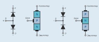
The main part of any amplifier is a device called a transistor. It consists of three separate semiconductor elements that have electrical contacts - a collector, a base, and an emitter. When alternating current flows through them, depending on its direction, the transistor increases or decreases the power of the input signal.
What is a quadripole
In electronics, a black box is a quadripole . What is a quadripole anyway? A four-terminal network is a black box containing an unknown electrical circuit inside. Here we see two input terminals, through which the input action is supplied, and two output terminals, from which we will now take the response of our “electric black box”.
Passive quadripole
For example, an RC circuit is a passive four-terminal network , since it has four terminals: two for input and two for output, and as we can see, it does not contain any power supply. This RC circuit is a passive low pass filter (LPF).
In passive two-terminal networks, the voltage or current at the output can be greater than at the input, but the power does not increase. How can the voltage or current at the output be greater than at the input? Here it is enough to recall the transformer, as well as series and parallel oscillatory circuits. For them, it would be more accurate to define a voltage converter, but not an amplifier, since the amplifier must include a power source from which it will take energy to amplify a weak input signal.
Also, in a passive four-port network, the output power will in no way be greater than the input power. If you achieve this, you will immediately receive an eternal source of energy and a Nobel Prize to boot. But remember that the law of conservation of energy, which was first formulated by Leibniz in the 17th century, has not been canceled.
Active quadripole
But we will now call this four-terminal network active , since it includes a power supply +Upit, which is required in order to amplify the signal.
That is, here we see two terminals for the input, to which the signal Uin is driven, and we also see two terminals for the output, where the voltage Uout is removed. Our four-port network is powered via + Upit, as a result of which, in this case, the output signal will be greater than the input signal.
By driving a sinusoid into the input of such a circuit, at the output we will get the same sinusoid , but its amplitude will be many times greater.
This is, of course, true for an ideal amplifier, i.e. absolutely linear and without restrictions on the amplitude of the input and output signals. In real amplifiers, it is required that the amplitude does not exceed the permissible value and that the amplifier is properly designed. In addition, any real amplifier introduces distortion and is characterized by nonlinear distortion coefficient (THD) and many other parameters, which we will consider in the next article.
In an active four-port network , one of which is a power amplifier, the output power will be greater than the input. Naturally, this does not violate the law of conservation of energy, since the power released to the load is the converted power of the power source. The small signal input simply controls this power. You can read more in the article about the principle of transistor amplification.
In electronics, we will consider an amplifier as an active four-port network , to the input of which a low-power signal Uin is supplied, and a load Rн is attached to the output.
Amplifier amplitude response
The amplitude characteristic is the dependence of the amplitude of the output voltage (current) on the amplitude of the input voltage (current) (Fig. 2.2).
Point 1 corresponds to the noise voltage measured at Uвx = 0, point 2 corresponds to the minimum input voltage at which the signal can be distinguished from the background noise at the amplifier output.
Section 2 - 3 is the working section in which the proportionality between the input and output voltages of the amplifier is maintained.
After point 3, nonlinear distortions of the input signal are observed. The degree of nonlinear distortion is estimated by the nonlinear distortion factor (or harmonic distortion):
KG = √(U22m + U23m + … + U2nm) / Ulm
where Ulm, U2m, U3m, Unm are the amplitudes of the 1st (fundamental), 2nd, 3rd and nth harmonics of the output voltage, respectively. The value D = Uin max / Uin min characterizes the dynamic range of the amplifier. Let's consider an example of the occurrence of nonlinear distortions (Fig. 2.3).
When a sinusoidal voltage ube is applied to the base of the transistor relative to the emitter, due to the nonlinearity of the input characteristic of the transistor ib = f(ube), the input current of the transistor ib (and therefore the output - collector current) is different from the sinusoid, i.e. a number of higher values appear in it harmonics
From the above example it is clear that nonlinear distortions depend on the amplitude of the input signal and the position of the operating point of the transistor and are not related to the frequency of the input signal, i.e., to reduce the distortion of the output signal shape, the input signal must be low-level.
Therefore, in multistage amplifiers, nonlinear distortions mainly appear in the final stages, the input of which receives signals with large amplitude.
Generalized amplifier circuit
It looks something like this:
As we can see in the diagram, some source of a weak signal with EMF EI and internal resistance RI is connected to the input of the amplifier stage through terminals 1 and 2. It is this weak signal from this source that we will amplify. Further, as expected, each amplifier has its own input resistance Rin. The current strength Iin in the circuit EI -> RI -> Rin, as difficult as it may be to guess, will depend on the input resistance of the amplifier stage Rin.
As you already know, the power supply plays a major role in the amplifier stage. A low-power, weak signal controls the energy consumption of the power supply. As a result, at the output we get an amplified copy of the weak input signal. The amplification occurred due to the fact that the power supply provided its power to amplify the input signal. Well, something like this).
In the output circuit of the amplifier we receive an amplified signal with EMF (What is EMF) Eout and output resistance Rout. Through terminal blocks 3 and 4 we connect the load Rн, which will already consume the energy of the amplified signal. The current strength in the circuit Eout -> Rout -> Rн will depend on the load resistance Rн.
Amplitude-frequency response (AFC) and phase-frequency response (PFC) of the amplifier.
The frequency response is the dependence of the gain modulus on frequency, and the phase response is the dependence of the phase angle between the input and output voltages on frequency. A typical frequency response is shown in Fig. 2.4.
The frequencies fн and fв are called the lower and upper limit frequencies, and their difference (fн - fв) is the amplifier bandwidth.
When a harmonic signal of sufficiently small amplitude is amplified, distortion of the shape of the amplified signal does not occur.
When a complex input signal containing a number of harmonics is amplified, the harmonics are amplified unequally by the amplifier because the circuit reactances vary with frequency, resulting in a distorted waveform of the amplified signal.
Such distortions are called frequency distortions and are characterized by the frequency distortion coefficient: M = K0 / Kf where Kf is the modulus of the amplifier gain at a given frequency.
Frequency distortion coefficients МН = K0 / KН and МВ = K0 / KВ are called distortion coefficients at the lower and upper limit frequencies, respectively. The frequency response can also be plotted on a logarithmic scale. In this case, it is called LFC (Fig. 2.5), the gain of the amplifier is expressed in decibels, and frequencies are plotted along the abscissa axis through a decade (frequency interval between 10f and f).
f = 10n are chosen as reference points . The LFC curves have a certain slope in each frequency region. It is measured in decibels per decade. A typical phase response is shown in Fig. 2.6. It can also be plotted on a logarithmic scale. In the mid-frequency region, additional phase distortion is minimal.
The phase response makes it possible to evaluate phase distortions that arise in amplifiers for the same reasons as frequency distortions.
An example of the occurrence of phase distortions is shown in Fig. 2.7, which shows the amplification of an input signal consisting of two harmonics (dotted line), which undergo phase shifts when amplified.
Amplifier types
Amplifiers can be divided into three groups:
Voltage amplifier
A voltage amplifier (VA) amplifies the input voltage a specified number of times. This coefficient is called voltage gain and is calculated by the formula:
Where
KU is the voltage gain
Uout - amplifier output voltage, V
Uin - voltage at the amplifier input, V
The output amplified voltage should not change from the load current, and therefore from the load resistance. Ideally, the output resistance Rout should be zero, which is unattainable in practice. Therefore, they try to design NAs in such a way as to minimize the output resistance Rout.
In this mode, the amplifier operates if the conditions are met that Rin is much greater than Rout, i.e. Rin >>Ri and Rn are much greater than Rout (Rn >>Rout). The higher the rating Rн, the better for the voltage amplifier, since the load will not sag the output voltage Uout. Everything is simple here: the lower the load resistance, the greater the current will flow through the circuit Eout -> Rout -> Rn, the greater the voltage drop across the output resistance Rout, based on the EMF formula: Eout = IoutRout + IoutRn. You can read about this in more detail in the article Ohm's Law for a complete circuit.
Current amplifier
The current amplifier (CA) amplifies the input current by a specified number of times. This coefficient is called the current gain and is calculated by the formula:
where KI is the current gain
Iout - current strength in the load circuit, A
Iin - current strength in the input circuit Ei ->Ri ->Rin, A
The meaning of the operation of the current amplifier is this: at a certain current strength in the input circuit, at the output in the load circuit we obtain a current strength that is KI times greater, regardless of what value the load rating takes. Ohm's simple law I=U/R already works here.
If the current strength must be constant, and our resistance value can be floating, then to maintain a constant current strength in the load circuit, our amplifier automatically changes the voltage Uout at the load. As a result, the current remained constant and remained the same. Or in letters: Rн =var, Iout= const.
You will tell your electronics teacher the above explanation, and now the explanation is for complete dummies . So, in the input circuit Ei -> Ri -> Rin, let us have a current flow of 10 mA. Coefficient KI = 100, therefore, at the output in the load circuit Eout -> Rout -> Rн a current with a force of 1 A (10 mA x 100) will flow. But such a current by itself will not flow through this circuit. It needs to create conditions for it to occur. Let's say we have a load of 10 ohms. What then should be the voltage in this circuit to obtain a current in this circuit of 1 A? Remember Uncle Om: I=U/R. 1=Uout/10, we get U=10 V. This is the voltage the current amplifier will give us at the output.
But what if the load changes its value? The current should remain the same, do not forget, that is, 1 A, since this is a current amplifier. In this case, so that the current in the circuit remains 1 A, the amplifier will automatically change its voltage value at the output Uout to 1=Uout /5. Uout =5/1=5 V. That is, we will already have 5 Volts at the output.
But we also do not forget about one more parameter, which is located in the output circuit of the current amplifier. This is the output resistance Rout. Therefore, we need the following condition to be satisfied: Rin << Ri and Rn << Rout at which the specified current in the load is ensured at a low voltage value.
Amplifier
It used to be very cool and fashionable to assemble power amplifiers (PA) with your own hands, turn on Tender May and turn the volume up to full blast. Now everyone can assemble or buy UM, since the Internet and Aliexpress are always at hand.
How does UM differ from UN and UT?
If in the UT we increased only the current, in the UN we increased the voltage, then in the UM we increased the current and voltage by a multiple of times.
The power formula for direct and alternating current with a resistive load looks like this:
Where
P—power, W
I - current strength, A
U—voltage, V
Therefore, the power gain will be written as:
Where
KP - power gain
Pout - amplifier output power, W
Pin - power at the amplifier input, W
For a power amplifier, the conditions for matching the input circuit with the source of the input signal and the output circuit with the load for transmitting maximum power have the form: Rin ≈ Ri and Rn ≈ Rout.
Also, do not forget that loads can be either purely active (such as an incandescent light bulb, a resistor, various heaters) or have a reactive component (inductors, capacitors, motors, etc.).
2.1. Three basic transistor amplifier circuits
Amplifier
– this is a device (four-port network) that increases the signal power. The increase in signal power occurs due to the conversion of power source energy into signal energy. When amplified, the signal shape must be preserved without significant distortion.
Amplifiers are used to compensate for losses when transmitting information signals over long distances, to ensure the operation of recording devices, to create normal conditions for human perception of information, etc. For example, to power the speakers of a multimedia computer, an amplifier is usually required, since the audio signals coming from the sources are insufficiently powerful.
By amplified electrical quantity
distinguish between:
,
voltage
and
amplifiers .
The amplifier's transmission coefficient for one of the indicated electrical parameters is, as a rule, much greater than unity. According to other parameters, the amplifier's transmission coefficient may be less than unity. However, all amplifiers, by definition, must have a power transfer coefficient greater than unity. Therefore, for example, a step-up transformer, whose voltage transfer coefficient may be greater than unity, does not belong to amplifiers.
By range of amplified frequencies
amplifiers are divided:
· for DC
(UPT);
on low
(sound)
frequencies
(ULF);
· for high frequency
(UHF);
· for ultra-high
(microwave) amplifiers.
In computers, for example, UFTs are used in power supplies, ULFs in sound cards, UHF and microwave amplifiers in receivers of radio and television signals. In the future, we will mainly consider only amplifiers of alternating voltages and currents, since such signals are the main ones in information transmission systems.
By elements used
There are amplifiers
based on transistors, microcircuits, vacuum tubes, diodes
, etc. Further we will consider amplifiers only on transistors and microcircuits. Such amplifiers are widely used in computers.
By operating modes
a distinction is made between
linear
and
nonlinear
amplifiers.
In linear amplifiers, the levels of input and output signals are low (for semiconductor elements Um
< 0.1 V) and therefore all amplifier elements, when exposed to small alternating signals, are characterized by a linear relationship between currents and applied voltages.
If the signal amplitude is large ( Um
> 0.1 V for semiconductor elements), then the linear relationship between currents and voltages is violated. A nonlinear operating mode of the amplifier arises. Next we will consider amplifiers operating only in linear mode.
Amplifiers are also classified by the number of stages, by purpose, by the frequency band of the amplified frequencies, by the nature of the amplified signal, etc.
Key indicators
amplifier are
the gain factors for voltage, current, power
:
,
as well as resistance, input
() and
output
(). Additional parameters of the amplifier include: efficiency, power consumed from the power supply, nonlinear distortion, weight and dimensions, etc.
The circuitry of transistor amplifiers is diverse and complex. However, in this diversity, three main schemes can be distinguished, on the basis of which more complex schemes are built. When using bipolar transistors, a distinction is made between:
common emitter amplifier
(OE);
common base amplifier
(ABOUT);
amplifier with common collector
(OK).
According to the alternating voltage in these circuits, the emitter, base or collector of the transistor is connected to the amplifier body, respectively.
In a common emitter circuit
(Fig. 2.1) the emitter of the transistor is connected to the amplifier body.
Through a coil with a high inductance, called a choke Dr
, a bias voltage
EBE
= 0.5...0.8 V is applied to the base of the transistor. This voltage is intended to open the emitter junction and provide a constant collector current in the active mode of operation of the transistor.
t/image_post/electronika_lanovenko/pic20_4.gif align=left>
The value of the initial direct collector current is determined by the technical operating conditions and for low-power transistors is approximately equal to
IКН
= 0.1...10 mA.
Power amplification is carried out using the energy of the power source ( PS
). The power supply voltage is usually 5...20 V, and the polarity is set to close the collector junction.
Together with supply voltage ( EP
) current (
ICN
) and bias voltage (
EBE
) determine
the DC mode of
the amplifier. The described DC mode is a prerequisite that makes it possible to amplify weak signals in the amplifier. If the transistor is turned off and the transistor's DC collector current is zero, then the cascade will not amplify weak AC signals.
The combination of alternating currents and voltages on the elements of the cascade determines the mode
amplifier
for alternating voltage
.
Through the capacitor CP
(Fig. 2.1), the alternating input signal is supplied to the base of the transistor and controls the relatively large collector current.
CP
capacitor in the circuit has a large capacity.
Consequently, its capacitance ( Xc = 1/ wCP
) is small, and therefore it passes alternating input current well.
The main purpose of this capacitor is to prevent DC voltage that may be present in the input signal from passing through to the amplifier input. Therefore, the capacitor CP
called
dividing
. In the circuit under consideration, the separating capacitor, in addition, does not pass the constant bias voltage present at the base of the transistor to the input terminal of the amplifier. Often an amplifier with a coupling capacitor installed at the input is called an amplifier with a “closed” input.
Throttle Dr
(see Fig. 2.1) the bias voltage passes, since the coil's resistance to direct current is zero. For alternating current, this inductor, having a large inductance, creates a large resistance. The input alternating current is practically not branched through the inductor, but all is supplied to control the transistor. Therefore, this choke is also often called a separating choke, but the alternating potentials are separated here.
The collector circuit (Fig. 2.1) includes a resistance to the internal load of the cascade, through which part of the alternating current of the collector flows. Most of the alternating current of the collector through the output coupling capacitor flows through the external amplifier load connected to the output terminal of the stage (see Fig. 2.1). This load produces a power-amplified alternating signal.
In a common base amplifier circuit
(Fig. 2.2) the purpose of the separation capacitors, inductor, and collector resistance is similar to their purpose in the OE circuit. Unlike the common-emitter circuit in the OB amplifier, a negative bias voltage is applied through the inductor Dr to the emitter of the transistor. Only with such polarity of the bias voltage does the transistor open, direct current begins to flow through it, and only in this case will the OB amplifier be able to amplify weak alternating signals.
In an amplifier circuit with a common collector
the blocking capacitor SBL
plays an important role . Having a large capacitance and therefore low resistance, a blocking capacitor is used to make the alternating potentials of the two nodes almost identical. Thus, the flow of alternating voltage from one part to another is “blocked”.
In the OB amplifier (Fig. 2.3), the main purpose of the blocking capacitor is to connect the transistor collector via alternating voltage to the amplifier body through its low resistance. Therefore, at a point on the collector, the alternating voltage will be practically zero, which corresponds to the OK circuit. Unlike common emitter and common base circuits, the collector of the transistor in a common collector
(see Fig. 2.3) is not connected to the housing. There is a large DC voltage present at the collector from the power supply.
Note that in the absence of a blocking capacitor, the circuit under consideration (
Amplifier output power
The output power of the amplifier delivered to the active load will be expressed by the formula:
Where
Pout - amplifier output power, W
Iout - current strength in the load circuit, A
UOut—load voltage, V
The power to the load with a reactive component will already be expressed through the formula:
Where
Pout - amplifier output power, W
Iout - current strength in the load circuit, A
Uout—load voltage, V
cosφ - where φ is the phase difference between the current and voltage oscillogram
For example, the phase difference between current and voltage in a resistive load is zero, therefore cos0=1. Therefore, the formula for the active load takes the form
You can read more about this in the article about active and reactance.
The maximum output power at which the distortion of the output signal does not exceed the quality values of the amplifier is called the rated power of the amplifier .
Well, a general rule, in order to make it easier to remember all these three types of amplifier:
In UN KU > 1, KI = 1; in UT KI > 1, KU = 1; in the mind KU > 1 and KI > 1.
Electronics for everyone
They often started asking me questions about analog electronics. Did the session take the students for granted? Okay, it’s high time to start a little educational program. In particular, on the operation of operational amplifiers. What is it, what is it eaten with and how to calculate it.
What is this
An operational amplifier is an amplifier with two inputs, neve... hmm... high signal gain and one output. Those. we have Uout = K*Uin and K ideally equals infinity. In practice, of course, the numbers are more modest. Let's say 1,000,000. But even such numbers blow your mind when you try to apply them directly. Therefore, like in kindergarten, one Christmas tree, two, three, many Christmas trees - we have a lot of reinforcement here and that’s it.
And there are two entrances. And one of them is direct, and the other is inverse.
Moreover, the inputs are high-impedance. Those. their input impedance is infinity in the ideal case and VERY high in the real case. The count there goes into hundreds of MegaOhms, or even gigaohms. Those. it measures the voltage at the input, but has minimal effect on it. And we can assume that no current flows in the op-amp.
The output voltage in this case is calculated as:
Uout=(U2-U1)*K
Obviously, if the voltage at the direct input is greater than at the inverse input, then the output is plus infinity. Otherwise it will be minus infinity.
Of course, in a real circuit there will not be infinity plus and minus, and they will be replaced by the highest and lowest possible supply voltage of the amplifier. And we get it: Comparator
A device that allows you to compare two analog signals and make a verdict - which signal is larger.
Already interesting. You can come up with a lot of applications for it. By the way, the same comparator is built into most microcontrollers, and I showed how to use it using the example of an AVR in articles about using an analog comparator
and about creating
an ADC based on it
.
The comparator is also great for creating all sorts of PWM signals
.
But the matter is not limited to one comparator, because if you introduce feedback, then a lot can be done from the op-amp.
Feedback
If we take a signal from the output and send it straight to the input, then feedback will arise.
Positive Feedback
Let’s take and drive the signal directly from the output into the direct input.
What will we get? But nothing interesting, the process will follow the following chain of events.
Uout = (0 - U1)*K = - K*U1 Uout' = (-K*U1 - U1)*K1 ...
In general, the output will instantly fall into endless minuses, and in reality it will fall on the negative power bus and the mustache. Therefore, such inclusion is used extremely rarely. For example, in a Schmitt trigger to provide hysteresis.
Schmitt trigger
Let's imagine a comparator connected according to this circuit and powered by +/- 15 volts:
- The voltage U1 is greater than zero - the output is -15 volts
- The voltage U1 is less than zero - the output is +15 volts
What happens if the voltage is zero? In theory, the output should be zero. But in reality, the voltage will NEVER be zero. After all, even if the charge of the right one outweighs the charge of the left one by one electron, then this is already enough to drive the potential to the output at an infinite gain. And at the output all hell will begin - the signal jumps here and there at the speed of random disturbances induced at the inputs of the comparator.
To solve this problem, hysteresis is introduced. Those. a kind of gap between switching from one state to another. To do this, positive feedback is introduced, like this:
We assume that at this moment there is +10 volts at the inverse input. The output from the op-amp is minus 15 volts. At the direct input it is no longer zero, but a small part of the output voltage from the divider. Approximately -1.4 volts Now, until the voltage at the inverse input drops below -1.4 volts, the op-amp output will not change its voltage. And as soon as the voltage drops below -1.4, the output of the op-amp will sharply jump to +15 and there will already be a bias of +1.4 volts at the direct input.
And in order to change the voltage at the output of the comparator, the U1 signal will need to increase by as much as 2.8 volts to reach the upper level of +1.4.
A kind of gap appears where there is no sensitivity, between 1.4 and -1.4 volts. The width of the gap is controlled by the ratios of resistors in R1 and R2. The threshold voltage is calculated as Uout/(R1+R2) * R1 Let's say 1 to 100 will give +/-0.14 volts.
But still, op-amps are more often used in negative feedback mode.
Negative Feedback
Okay, let's put it another way:
In the case of negative feedback, the op-amp has an interesting property. It will always try to adjust its output voltage so that the voltages at the inputs are equal, resulting in a zero difference. Until I read this in the great book from comrades Horowitz and Hill, I could not get into the work of the OU. But it turned out to be simple.
Repeater
And we got a repeater. Those. at input U1, at inverse input Uout = U1. Well, it turns out that Uout = U1.
The question is, why do we need such happiness? It was possible to directly connect the wire and no op-amp would be needed!
It is possible, but not always. Let's imagine this situation: there is a sensor made in the form of a resistive divider:
The lower resistance changes its value, the distribution of output voltages from the divider changes. And we need to take readings from it with a voltmeter. But the voltmeter has its own internal resistance, albeit large, but it will change the readings from the sensor. Moreover, what if we don’t want a voltmeter, but want the light bulb to change brightness? There’s no way to connect a light bulb here anymore! Therefore, we buffer the output with an operational amplifier. Its input resistance is huge and its influence will be minimal, and the output can provide quite a noticeable current (tens of milliamps, or even hundreds), which is quite enough to operate the light bulb. In general, you can find applications for a repeater. Especially in precision analog circuits. Or where the circuitry of one stage can affect the operation of another, in order to separate them.
Amplifier
Now let’s do a feint with our ears - take our feedback and connect it to the ground through a voltage divider:
Now half of the output voltage is supplied to the inverse input. But the amplifier still needs to equalize the voltages at its inputs. What will he have to do? That's right - raise the voltage at your output twice as high as before in order to compensate for the resulting divider.
Now there will be U1 on the straight line. On inverse Uout/2 = U1 or Uout = 2*U1.
If we put a divisor with a different ratio, the situation will change in the same way. So that you don’t have to turn the voltage divider formula in your mind, I’ll give it right away:
Uout = U1*(1+R1/R2)
It is mnemonic to remember what is divided into what is very simple:
Thus, you can very easily multiply analog values by numbers greater than 1. But what about numbers less than one?
Inverting amplifier
Only an inverse amplifier will help here. The only difference is that we take the direct input and shorten it to the ground.
In this case, it turns out that the input signal goes through a chain of resistors R2, R1 in Uout. In this case, the direct input of the amplifier is set to zero. Let us remember the habits of the op-amp - it will try, by hook or by crook, to ensure that a voltage equal to the direct input is generated at its inverse input. Those. zero. The only way to do this is to lower the output voltage below zero so that a zero appears at point 1.
So. Let's imagine that Uout=0. It's still zero. And the input voltage, for example, is 10 volts relative to Uout. A divisor of R1 and R2 will divide it in half. Thus, at point 1 there are five volts.
Five volts is not zero and the op amp lowers its output until point 1 is zero. To do this, the output should become (-10) volts. In this case, relative to the input, the difference will be 20 volts, and the divider will provide us with exactly 0 at point 1. We have an inverter.
But we can also choose other resistors so that our divider produces different coefficients! In general, the gain formula for such an amplifier will be as follows:
Uout = - Uin * R1/R2
Well, a mnemonic picture for quickly memorizing xy from xy.
Subtractive circuit
However, no one bothers to apply not zero, but any other voltage to the direct input. And then the amplifier will try to equate its inverse input to it. This results in a subtractive circuit:
Let's say U2 and U1 are 10 volts each. Then at the 2nd point there will be 5 volts. And the output will have to become such that at the 1st point there is also 5 volts. That is, zero. So it turns out that 10 volts minus 10 volts equals zero. That's right
If U1 becomes 20 volts, then the output will have to drop to -10 volts. Do the math yourself - the difference between U1 and Uout will be 30 volts. The current through resistor R4 will be (U1-Uout)/(R3+R4) = 30/20000 = 0.0015A, and the voltage drop across resistor R4 will be R4*I4 = 10000*0.0015 = 15 volts. Subtract the 15 volt drop from the 20 input drop and get 5 volts.
Thus, our op-amp solved an arithmetic problem from 10 subtracted 20, resulting in -10 volts.
Moreover, the problem contains coefficients determined by resistors. It’s just that, for simplicity, I have chosen resistors of the same value and therefore all coefficients are equal to one. But in fact, if we take arbitrary resistors, then the dependence of the output on the input will be like this:
Uout = U2*K2 - U1*K1 K2 = ((R3+R4) * R6 ) / (R6+R5)*R4 K1 = R3/R4
The mnemonic technique for remembering the formula for calculating coefficients is as follows: Directly according to the scheme. The numerator of the fraction is at the top, so we add up the upper resistors in the current flow circuit and multiply by the lower one. The denominator is at the bottom, so we add up the lower resistors and multiply by the upper one.
If the input resistors (R4 and R5) are equal to each other. Both the feedback resistor and the ground resistor (R3 and R6) are also equal to each other. Then the formula simplifies to
Uout = R3/R4 (U2 - U1).
Thus, on one amplifier, two signals can first be subtracted and then multiplied by a constant. By the way, I used this in the reobass circuit
to bring the millivolt signal from the temperature sensor to a sane form.
If you can subtract, you can also add
Inverting adder
Everything is simple here. Because point 1 is constantly reduced to 0, then we can assume that the currents flowing into it are always equal to U/R, and the currents entering node number 1 are summed up. The ratio of the input resistor to the feedback resistor determines the weight of the incoming current.
There can be as many branches as you like, but I only drew two.
Uout = -1(R3*U1/R1 + R3*U2/R2)
Resistors at the input (R1, R2) determine the amount of current, and therefore the total weight of the incoming signal. If you make all the resistors equal, like mine, then the weight will be the same, and the multiplication factor of each term will be equal to 1. And Uout = -1(U1+U2)
Non-inverting adder
Everything is a little more complicated here, but it’s similar.
Uout = U1*K1 + U2*K2
K1 = R5/R1 K2 = R5/R2
Moreover, the resistors in the feedback must be such that the equation R3/R4 = K1+K2 is observed
In general, you can do any math using operational amplifiers, add, multiply, divide, calculate derivatives and integrals. And almost instantly. Analog computers are made using op-amps. I even saw one of these on the fifth floor of SUSU - a fool the size of half a room. Several metal cabinets. The program is typed by connecting different blocks with wires
To be continued someday
Types of amplifiers by bandwidth
Based on bandwidth, amplifiers are divided into:
Low Frequency Amplifiers
They are also called audio frequency amplifiers (AF). They are designed to amplify signals with frequencies from tens of Hertz to 20 kHz. 20 kHz is the limit of frequency that can be perceived by the human ear. Therefore, this type of amplifier is very popular among music lovers and radio amateurs.
High frequency amplifiers
They are designed to amplify signals over the entire range of frequencies used by electronics.
Broadband amplifiers
They allow amplification of a wide frequency band (for example, from tens of hertz to several megahertz). Here, I think, everything is clear.
Narrowband amplifiers
They amplify a narrow frequency band. These can be resonant filters, as well as filters that are based on UHF and ULF.
Application in Wi-Fi
In the modern information era, it is difficult to imagine your life without access to the World Wide Web. The most popular type of wireless connection is undoubtedly Wi-Fi. However, this technology has a noticeable disadvantage - limited range. In the absence of obstacles, devices can receive the network at a distance of only up to 100 meters. This is not always convenient, especially for large companies or firms whose branches are located in different areas of the city.
WiFi amplifiers eliminate this disadvantage. These are special repeater devices that receive a weak electromagnetic signal, convert it into a more powerful one and relay it to nearby Internet signal receivers. WiFi amplifiers are increasingly becoming popular in rural areas, making this type of Internet connection no less popular than a mobile one.