The design and technical construction of synchronous electric motors determines the peculiarities of their functioning and use. One of the main differences between machines of this type is the impossibility of starting them when connected directly to the power supply.
Synchronous motors, like asynchronous machines, are AC electric drives that convert electricity into mechanical movement of a shaft. Due to the different operating principle, there are a number of mandatory conditions for correct operation and operation. One of these requirements is the startup of electrical equipment.
Purpose and design
Before moving on to a detailed consideration of the process of starting a synchronous motor (SM), it would be useful to briefly repeat the main aspects of the theory. What is SD, how its elements interact, what types there are and why this type of electric drive is called that. After this, you can consider starting methods.
A synchronous motor (SM) is an electrical equipment whose operation is provided by an electromotive force arising from the interaction of the magnetic fields of the stator and rotor mechanism. This principle is fundamental for the design of electric motors of various types. Despite the uniform approach, drive equipment has its differences.
The main feature is the design of the moving mechanism and the principle of its rotation. Depending on the required power, the rotor can:
- contain permanent magnets and be the initiator of magnetoelectric excitation;
- represent electromagnets that initiate electromagnetic excitation.
The first option is used for low-power electric machines. Permanent magnets are made of hard magnetic materials capable of maintaining a state of magnetization. They can have either a built-in or surface location on the rotor.
The second type of design of the rotor unit involves the installation of a ferromagnetic core with an electrical winding. When energized, such a system is a source of magnetic flux that interacts with the stator field.
The definition of synchronism, that is, sameness, is based on the equality of the rotor speed and the stator magnetic field. This is the key difference in the operating principle of electrical equipment, which determines its technical capabilities, operating features and scope of application. The same factor directly affects the starting of synchronous motors.
Trapezoidal control
This scheme is used for valve motors. The design of such machines is no different from PMSM. Their main feature is the principle of nutrition. A trapezoidal voltage is applied to the HP stator windings. Phase switching is carried out depending on the angle of rotation of the rotor.
HP control circuits are also available with and without a sensor. Hall sensors are usually used as a feedback device. The greater their number, the more accurately the rotation angle is determined. For example, 3 Hall sensors allow you to determine the rotor position with an accuracy of ±300. Sensorless control systems determine positions based on previously known functions. Such schemes are used to solve simple problems.
Launch Aspects
The operating principle of the SD imposes a number of requirements, without which not only a smooth start, but also the start of the synchronous electric motor itself is impossible. In an LED, a rotating field is created by a three-phase current in the stator circuits. In this case, the power developed on the electric motor shaft is compensated by the power coming from the supply network. That is, the interaction of the stator device current with the field of the rotor mechanism initiates the occurrence of torque.
As already mentioned, the speeds of the rotor and the fields of the stator assembly are synchronous. If a difference occurs during a certain period of time, the poles of the rotor-stator mechanism will be located opposite each other. As a result, the magnetic connection will be disrupted, since like poles will repel each other. The rotor will stop experiencing torque and stop. Therefore, ensuring simultaneous rotation for a synchronous motor is a fundamental condition for its operation.
But self-startup with a direct network connection is not possible. The rotor mechanism, due to its inertia, is not able to quickly reach the frequency of the stator field, while the rotation of the latter is established simultaneously with the connection to the power supply network. Therefore, a stable connection creating torque does not arise between the poles of the excited rotor assembly and the rotating field.
Advantages and disadvantages
If we compare synchronous electric motors with asynchronous motors, the former clearly have a more complex mechanism, but we also need to highlight their significant advantages:
- The operation of synchronous motors is not particularly dependent on voltage intensity.
- An important advantage of synchronous motors is their relatively small size, while their efficiency and mechanical functions are much better.
- No matter what the load fluctuations are, it will not affect the revolutions and rotation speed in any way.
- Even in the case of significant overloads on the shaft, the synchronous motor will operate without problems, compensating for such peak surges by increasing the current in the field winding.
- Synchronous motors can operate in the same way as compensators due to the fact that they can produce reactive energy. To do this, you need to apply increased voltage to the excitation winding. If you set the excitation current in the optimal mode, reactive energy will not be consumed, and it will not go to the network.
With all the above advantages of using synchronous electric motors, we must also note one main drawback - the lack of starting torque. That is, to start the engine, it is necessary to use separate equipment.
This is precisely the main reason why synchronous motors have been limited in use for a long time.
Inclusion methods
Based on the fact that direct starting is impossible, the inclusion of a synchronous motor in the work process is carried out with the implementation of additional measures. Regardless of the methods of starting an electric drive, the essence of each is to first set the moving part in motion at speeds close to the frequency of the main field.
When starting, the flux moves so slowly relative to the magnetic centers of the rotating shaft that when the exciting electrical winding is connected to the power source, a magnetic connection is established between the rotor poles and the stator field. It is this that ensures the occurrence of the same electromagnetic moment. Under its action, the electric motor shaft is pulled into synchronism.
There are several ways to start synchronous motors. Three of them have received practical application:
- through auxiliary electrical equipment;
- asynchronous, including autotransformer and reactor starting;
- frequency starting of a synchronous motor.
Each synchronous motor starting scheme has its own advantages and disadvantages regarding the complexity of the design and technical design, financial costs, and dimensions of the drive units. Therefore, where, for example, a reactor start-up would be optimal, it would be wiser not to use the more expensive frequency start-up. Which method is optimal depends on many factors.
Starting and stopping a synchronous motor must be carried out in compliance with a certain sequence of actions and conditions. Therefore, to reduce the risk of failure of the electric drive at the start, a system is provided to protect the synchronous motor from prolonged activation. And at the stopping stage, the following algorithm is observed:
- reduce the excitation current to a value equal to the minimum current parameters of the stator;
- turn off the stator assembly;
- open the exciting electrical circuit.
Deviation from this sequence is fraught with a jump in current values in the stator, overvoltages and, as a result, a violation of the integrity of the insulation.
Scope of application
Synchronous motors are more expensive than asynchronous motors, and they also require an additional source of direct current excitation - this partly reduces the range of applications of this type of electrical machines. However, synchronous electric motors are used to drive mechanisms where overloads are possible and precise maintenance of stable speed is required.
At the same time, they are most often used in the area of high power - hundreds of kilowatts and units of megawatts, and, at the same time, starting and stopping occur quite rarely, that is, the machines operate around the clock for a long time
This application is due to the fact that synchronous machines operate with cosPhi close to 1, and can supply reactive power to the network, as a result of which the power factor of the network is improved and its consumption is reduced, which is important for enterprises
Starting with auxiliary equipment
Starting up a synchronous motor with an additional drive is similar to the process of turning on a synchronous generator for parallel operation. In fact, the launch is carried out using an auxiliary (acceleration) electric motor. In this case, the shaft of the excited electric motor is set into rotation, accelerates to the required frequency and is connected to the electrical network through a synchronizing device. The auxiliary drive is then switched off.
This starting method involves the use of a machine with significantly lower power, amounting to 5-15% of the power of the SD. The use of a starting electric drive of greater load-bearing capacity, sufficient to accelerate a loaded motor, is irrational from the point of view of bulkiness and efficiency. Therefore, using this method, electric motors are started either without load or at its insignificant value.
The process of starting a synchronous motor is performed by an asynchronous motor with a wound rotor with two fewer poles compared to the number of poles of an SD. This is necessary to accelerate the shaft of the driven mechanism to the required speed. The speed of an asynchronous machine is controlled by an adjusting rheostat. In practice, this starting method is used only for powerful machines, because This type of drive for motors, for example, 6 kV, is not rational.
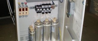
Reactor start-up
In this case, the engine is started at reduced mains voltage using a reactor or transformer. Reactor starting is recommended first of all, and only if it is impossible to use it, autotransformer starting is allowed.
Reactor starting of synchronous compensators (Fig. 5 - 1g), now accepted as the main one, is used for powerful machines.
Reactor, or autotransformer, starting is carried out by applying voltage to the windings of electric motors, reduced using an autotransformer or, most often, a reactor, which are turned off when the unit accelerates to a subsynchronous rotation speed. During reactor startups, the torque developed by the engine during startup, shocks and vibrations of the machine, power consumption, heating of the windings and voltage drop are reduced, and the startup time is increased.
Capacitor or reactor starting.
Starting of electric motors of the VDS 325 series is direct asynchronous from a network with full voltage. VDS 325 electric motors have a reactor start from a network with reduced voltage.
A three-phase asynchronous motor with a multiplicity of the initial starting current kj 5 6 and a multiplicity of the initial starting torque kn - 1 3 is started at a load Mv 0 5 Mn. Is reactor start-up applicable in this case?
Allows voltage regulation. When the substation power is up to static power, a reactor start or direct start from a spike is possible.
The electrical connection diagram of the pumping station must ensure direct starting of asynchronous and synchronous electric motors from the full network voltage. For powerful electric motors, in accordance with the instructions of the manufacturers, reactor starting can be used. The use of large synchronous electric motors for operation in compensatory mode during water supply interruptions must be justified by technical and economic calculations.
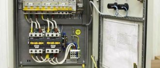
| Auxiliary diagram of current circuits for protecting electric motors with reactor starting from multiphase short circuits. a - when using current cut-off. b - when using differential protection. M - electric motor. L - starting reactor. Ql, Q2 - switches. TA1 - TAZ - current transformers. AK1, AK2 - sets of current cut-offs. AK - differential protection kit.| Schematic diagram of differential protection of an electric motor M with a relay. |
If differential protection is used, then in the protection arm on the power side, for the same purpose, a two-phase two-relay cutoff without a time delay is installed, which, to increase sensitivity, is taken out of action during the start of the electric motor. In Fig. 2.192 shows block diagrams of current protection circuits for electric motors with reactor starting.
Starting of synchronous compensators is carried out in various ways: asynchronous - directly from the network, from the accelerating motor, through an autotransformer and through a reactor; asynchronous starting is used only for low compensator powers. The simplest starting method, most often used in practice, is reactor starting of the compensator. Synchronous compensators of the KS type up to 30,000 kVA inclusive are air-cooled, and the compensator of the KSV-37500 kVA type is hydrogen cooled.
| Direct (a and reverse (b) circuits for switching on starting autotransformers. |
However, this advantage of autotransformer starting is achieved at the cost of significantly complicating and increasing the cost of starting equipment. Therefore, autotransformer starting is used less frequently than reactor starting, under more severe conditions, when reactor starting does not provide the required starting torque.
| Starting diagram for a synchronous motor with a reactor. |
All synchronous motor control devices are located at control stations. In Fig. Figure 39 shows a general view of the façade of the PN7028 control station for synchronous motors with reactor starting. In addition to the devices listed in the description of the starting circuit for the STM-4000-2 synchronous motor, the control station shows instruments and devices used in motor control.
Asynchronous launch
The most common starting method is the method using starting short-circuited (damper) electrical conductors located in the grooves of the pole elements. The electrical windings are made in the form of brass or metal rods, which are closed on both sides with copper rings (position “b” in the figure).
When starting, the field winding (OB) is closed to a resistor, and the stator circuit is connected to the power supply network (position “a”). The rotating field of the stator device induces an EMF in the rods, as a result of which currents arise in them. When they interact with the magnetic flux of the stator, an electromagnetic force Fem acts on each rod, causing rotation.
After reaching the pre-synchronous speed, the OB is connected to a constant power source. The resulting torque accelerates the electric motor rotor to synchronism. At this time, the EMF is no longer induced in the starting circuit, so the asynchronous torque is zero. Then the damper short-circuit electrical winding performs only a calming function, limiting possible vibrations of the shaft.
The process of starting a synchronous motor must be carried out with a closed OB to an active electrical resistance, the value of which should be approximately ten times greater than the electrical resistance of the exciting electrical circuit. In this case, short-circuiting the OB during the acceleration period is undesirable, since a closed circuit is formed on the rotor, creating an asynchronous torque. At half the presynchronous speed, the torque turns into a braking torque and a certain braking of the synchronous motor occurs. There is a so-called “dip” in the torque value, which significantly reduces the starting qualities of the SD.
There are other limitations and features of starting using short-circuit windings. This is due to the occurrence of a large inrush current at the start. In this regard, LEDs are connected to the AC network only with its appropriate power, which can withstand five- and seven-fold current loads relative to the rated values of the electric motor. If there is insufficient power in the electrical network to limit current surges, switching on is carried out using a reduced voltage. Such starting methods are called autotransformer or reactor starting.
Reactors and autotransformers provide a forced reduction in the rate of current rise and its magnitude in the working windings. Reactor starting involves the installation of reactors in each power supply circuit of the phase electric circuit of the LED. In this regard, the current values do not increase abruptly and the start-up is smoother than a direct start. When the electrical equipment accelerates to pre-synchronous speed, switch K1 removes the inductive component from the electrical circuit and the electric drive operates in normal mode.
Starting methods
Starting synchronous electric motors can be done in three ways - using an additional motor, asynchronous and frequency starting. When choosing a method, the design of the rotor is taken into account.
It is performed with permanent magnets, with electromagnetic excitation or combined. Along with the excitation winding, a short-circuited winding - a squirrel cage - is mounted on the rotor. It is also called damping winding.
Starting with booster motor
This starting method is rarely used in practice because it is technically difficult to implement. An additional electric motor is required, which is mechanically connected to the rotor of the synchronous motor.
With the help of an accelerating motor, the rotor is spun to values close to the stator field rotation speed (synchronous speed). After that, a constant voltage is applied to the rotor excitation winding.
Control is carried out using light bulbs that are connected in parallel to the switch that supplies voltage to the stator windings. The switch must be turned off.
Initially, the lamps blink, but when the nominal speed is reached, they stop lighting. At this moment, voltage is applied to the stator windings. After which the synchronous electric motor can operate independently.
The additional motor is then disconnected from the network, and in some cases it is disconnected mechanically. These are the features of starting with an accelerating electric motor.
Asynchronous launch
The asynchronous start method is the most common today. Such a launch became possible after changing the rotor design. Its advantage is that an additional accelerating motor is not needed, since in addition to the excitation winding, short-circuited squirrel cage rods were installed in the rotor, which made it possible to start it in asynchronous mode. Under this condition, this launch method became widespread.
We immediately recommend watching a video on the topic:
When voltage is applied to the stator winding, the motor accelerates in asynchronous mode. After reaching speeds close to the nominal speed, the excitation winding is turned on.
The electric machine enters synchronization mode. But it's not that simple. During start-up, a voltage arises in the excitation winding, which increases with increasing speed. It creates a magnetic flux that affects the stator currents.
In this case, a braking torque arises, which can stop the acceleration of the rotor. To reduce the harmful effects, the field windings are connected to a discharge or compensation resistor. In practice, these resistors are large, heavy boxes using steel spirals as the resistive element. If this is not done, then due to the increasing voltage, an insulation breakdown may occur. Which will lead to equipment failure.
After reaching a subsynchronous rotation speed, resistors are disconnected from the excitation winding, and a constant voltage is supplied to it from the generator (in a generator-motor system) or from a thyristor exciter (such devices are called VTE, TVU, and so on, depending on the series). As a result, the engine goes into synchronous mode.
The disadvantages of this method are large inrush currents, which causes a significant drop in the supply voltage. This may lead to the stopping of other synchronous machines operating on this line as a result of low voltage protection. To reduce this effect, the stator winding circuits are connected to compensation devices that limit starting currents.
It can be:
- Additional resistors or reactors that limit inrush currents. After acceleration, they are bypassed, and mains voltage is supplied to the stator windings.
- Application of autotransformers. With their help, the input voltage is reduced. When the rotation speed reaches 95-97% of the operating speed, switching occurs. The autotransformers are turned off, and AC voltage is supplied to the windings. As a result, the electric motor enters synchronization mode. This method is technically more complex and expensive. And autotransformers often fail. Therefore, in practice this method is rarely used.
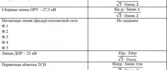
Frequency starting
Frequency starting of synchronous motors is used to start high-power devices (from 1 to 10 MW) with an operating voltage of 6, 10 kV, both in light starting mode (with a fan load) and heavy starting (ball mill drives). For these purposes, soft frequency starting devices are produced.
The operating principle is similar to high-voltage and low-voltage devices operating according to a frequency converter circuit. They provide starting torque up to 100% of the nominal value, and also provide starting of several motors from one device. You can see an example of a circuit with a soft starter below; it is turned on while the engine is starting, and then removed from the circuit, after which the engine is connected directly to the network.
Frequency switching
Frequency starting of a synchronous motor is performed using reduced voltage with a low current frequency. This is possible if there is a power source capable of adjusting the frequency to the required parameters. In this case, the speed of the magnetic flux will also be low, and the poles of the rotor assembly will rotate with it.
As the speeds become the same, the starting frequency of the supply current is gradually increased, accelerating the rotor to the nominal value. This starting method is considered soft, providing a smooth start. Its disadvantage is the need for a power source of adjustable frequency and voltage.
Modern frequency starting of a synchronous motor is implemented on the basis of circuits based on semiconductor elements - thyristor converters. They reduce the nature of the voltage change, practically without changing the effective value. This method of starting in automation systems provides a reduction in acceleration time, which has a positive effect on the performance of automated systems, but at the same time requires a more complex switching circuit.
Main directions of development of Danfoss controllers and frequency converters for PMSM
Permanent magnet synchronous motors are superior to DC machines in terms of control capability and precision. They allow you to implement many schemes and algorithms. Leading manufacturers of electrical equipment for drives, including Danfoss, have developed several lines of controllers and frequency converters for electric motors of this type. Further developments are underway in the following areas:
- Increasing the accuracy of control signal processing. The ability to change subsynchronous rotation speeds, determine the boundaries of dynamic modes, and carry out regulation over the entire permissible range.
- Reduced energy consumption. Algorithms are being developed that optimize the power consumed by PMSMs by supplying demagnetizing currents.
- Increasing torque stability at low speeds by eliminating pulsations.
- Simplification of control algorithms, which will allow the use of cheaper controllers and inverters.
- Reducing the number of sensors. An encoderless electric drive is more reliable, however, it is more sensitive to the variation in characteristics.
- Reducing the drive's sensitivity to interference. When the back EMF increases at low speeds in field-oriented control circuits without a feedback sensor, the sensitivity to interference increases.
- Creation of controllers for using PMSMs as servomotors in complex dynamic systems with high requirements for the accuracy of command execution.
Danfoss can offer technical solutions for controlling permanent magnet synchronous motors that meet modern electric drive requirements.
Source
Motor protection at start
The synchronous motor delay protection system is designed to reduce the negative impact of excessively high torque that occurs when the motor starts up. The reason for the occurrence of large torque values is insufficient excitation or its absence in the electric motor during start. The protection scheme provides for the use of:
- zero current relay, which controls the current load during excitation;
- a time relay that counts the duration of a normal start.
The protection system for a synchronous motor against prolonged starting is triggered when the excitation current in the electric motor has not reached a sufficient level within the time corresponding to a normal start. In this case, the protective system against a delayed start interrupts the switching process by turning off the power to the stator. Such a protection circuit belongs to the category of special functions of electric drives, simultaneously with protection against electrical winding breakage, overspeed, overvoltage, etc.
Methods of starting synchronous motors and typical circuits: advantages and disadvantages
Synchronous motors are typically used to drive large electrical drives as efficiently as possible.
Equipment with high power is used in many industrial fields; it can be used, for example, by metallurgical or oil and gas companies.
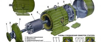
Such enterprises use ventilation units, compressors, electric pumps, and machine systems for pressurizing metals between rotating rolls. Today we will give you an overview of how synchronous motors work.
Synchronous machines. DC machines
Home > Textbook >Physics
b) less sensitivity to voltage fluctuations, since its maximum torque is proportional to the voltage to the first power (and not the square of the voltage);
c) strict constancy of rotation speed, regardless of the mechanical load on the shaft.
The disadvantages of synchronous motors are:
a) complexity of the design;
b) the comparative complexity of launching;
c) difficulties with regulating the rotation speed, which is only possible by changing the frequency of the supply voltage.
These disadvantages of synchronous motors make them less profitable than asynchronous motors with limited powers up to 100 kW. However, at higher powers, when it is especially important to have a high cosφ and reduced overall dimensions of the machine, synchronous motors are preferable to asynchronous ones.
14 Starting a synchronous motor
Asynchronous start method. A synchronous motor does not have an initial starting torque. If it is connected to an alternating current network when the rotor is stationary and direct current passes through the excitation winding, then during one period of current change the electromagnetic torque will change its direction twice, i.e. the average moment over the period will be zero. Under these conditions, the engine will not be able to start rotating, since its rotor, which has a certain inertia, cannot be accelerated to a synchronous rotation speed within one half-cycle. Consequently, to start a synchronous motor, it is necessary to accelerate its rotor using an external torque to a rotation speed close to synchronous.
Currently, the asynchronous starting method is used for this purpose. With this method, a synchronous motor is started as an asynchronous one, for which it is equipped with a special short-circuited starting winding, made like a squirrel cage. Typically, this cage is made of brass in order to increase the resistance of the rods. When a three-phase armature winding is connected to the network, a rotating magnetic field is formed, which, interacting with the current I p in the starting winding (Fig. 1. 48, a), creates electromagnetic forces F and drags the is a rotor. After the rotor accelerates to a rotation speed close to synchronous, the direct current passing through the field winding creates a synchronizing torque, which pulls the rotor into synchronism.
Rice. 1. 48 – Design of the starting winding of a synchronous motor (a) and its asynchronous starting circuit (b, c): 1 - field winding, 2 - starting winding, 3 - rotor, 4 - armature winding, 5 - quenching resistor, 6 - armature exciter, 7 – rings and brushes
Currently, two main schemes for starting a synchronous motor are used. With the scheme shown in Fig. 1. 48, b, the excitation winding is first closed to a quenching resistor, the resistance of which r is 8–12 times higher than the active resistance r in the excitation winding. After the rotor accelerates to a rotation speed close to synchronous (at s = 0.05), the excitation winding is disconnected from the damping resistance and connected to a direct current source (exciter), as a result of which the rotor is pulled into synchronism. It is impossible to start a motor with an open field winding, since during acceleration of the rotor at s > 0 a rotating magnetic field is induced in it. d.s.
where Ф m is the amplitude of the magnetic flux of the rotating field; ω in – number of turns of the excitation winding; f 2 = f 1 s - frequency of current change in the field winding.
At the initial moment of start-up at s ≈ 1, due to the large number of turns ω in the excitation windings, the emf. E in can reach a very large value and cause an insulation breakdown.
With the scheme shown in Fig. 1.48, in, the excitation winding is constantly connected to the exciter, the resistance of which is very small compared to the resistance r in, therefore this winding in the asynchronous start mode can be considered short-circuited. As the slip decreases to s = 0.3 4–0.4, the exciter is excited and a direct current is supplied to the excitation winding, ensuring that at s ≈ 0.05 the rotor is pulled into synchronism.
The difference in starting circuits is due to the fact that not in all cases a simpler circuit with an excitation winding permanently connected to the exciter can be used (Fig. 1.48, c), since it has worse starting characteristics than the more complex circuit shown in Fig. 1.48, b. The main reason for the deterioration of starting characteristics is the occurrence of a uniaxial effect - the influence of the current induced in the field winding during starting on the starting torque characteristic.
To analyze this phenomenon, let us first assume that the motor does not have a starting winding, and the field winding is short-circuited. As a result, when the motor is started asynchronously, an emf is induced in the excitation winding. with a frequency f 2 = f 1 s and an alternating current passes through the winding, creating a pulsating magnetic field (the field winding in this case is a single-phase alternating current winding). The pulsating magnetic field can be decomposed into two components: direct and reverse rotating magnetic fields of the rotor, which are characterized by the fluxes F pr and F obr. The rotation frequency of each of these fields relative to the rotor
Relative to the stator, the direct field rotates with a frequency
where n 2 = n 1 ( 1 - s ) – rotor speed.
Consequently, it rotates synchronously with the stator field; The electromagnetic torque M pr formed by this field with the stator current varies depending on the slip in the same way as in a three-phase asynchronous motor (Fig. 1.49, curve 2). The reverse rotor field rotates relative to the stator with a frequency
At rotor speeds n 2 n 1, i.e. for s > 0.5, the reverse field, as can be seen from formula (1.45), moves relative to the stator in the direction opposite to the direction of rotation of the rotor; when n 2 = 0.5 n 1 this field is motionless relative to the stator; at n 2 > 0.5 (i.e. at sf 1 (1–2 s ), for which the stator winding is short-circuited. In this case, a corresponding current flows through the stator winding. Interacting with the reverse field of the rotor, this current creates an electromagnetic moment M arr. Since the direction of the torque depends on the direction of rotation of the field n r.rev relative to the stator, it follows from formula (1.45) that it is alternating and a change in its direction occurs at s = 0.5 (Fig. 1.49, curve 3 ) .