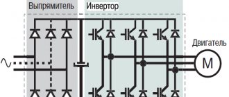
What is an asynchronous motor?
AC electric motors have found quite wide application in various spheres of our life, in hoisting, processing, and measuring equipment. They are used to convert electrical energy that comes from the network into mechanical energy of a rotating shaft. Most often, asynchronous AC converters are used. In them, the rotation speed of the rotor and stator is different. A structural air gap is provided between these active elements.
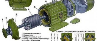
Both the stator and the rotor have a rigid core made of electrical steel (composited type, made of plates), acting as a magnetic circuit, as well as a winding that fits into the structural grooves of the core. It is the way in which the rotor winding is organized or laid out that is the key criterion for classifying these machines.
Squirrel-cage motors (SCR)
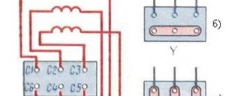
Here, a winding is used in the form of aluminum, copper or brass rods, which are inserted into the grooves of the core and closed on both sides by disks (rings). The type of connection of these elements depends on the engine power: for small values, the method of joint casting of disks and rods is used, and for large values, separate production is used, followed by welding to each other. The stator winding is connected using delta or star circuits.
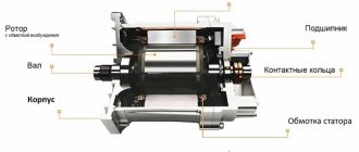
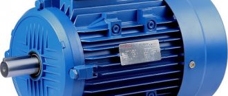
Wound rotor motors
The three-phase rotor winding is connected to the network via slip rings on the main shaft and brushes. The “star” scheme is taken as the basis. The figure below shows a typical design of such an engine.
Voltage regulation
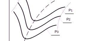
Speed control in this way is associated with a change in the so-called engine slip - the difference between the rotation speed of the magnetic field created by the stationary engine stator and its moving rotor:
n1— magnetic field rotation speed
n2 — rotor rotation speed
In this case, sliding energy is necessarily released - which causes the motor windings to heat up more.
This method has a small control range, approximately 2:1, and can also only be carried out downwards - that is, by reducing the supply voltage.
When regulating speed in this way, it is necessary to install oversized motors.
But despite this, this method is used quite often for low-power motors with a fan load.
In practice, various regulator circuits are used for this.
Autotransformer voltage regulation
An autotransformer is an ordinary transformer, but with one winding and taps from some of the turns. In this case, there is no galvanic isolation from the network, but in this case it is not needed, so savings are achieved due to the absence of a secondary winding.
The diagram shows autotransformer T1 , switch SW1 , which receives taps with different voltages, and motor M1.
The adjustment is done in steps; usually no more than 5 steps of regulation are used.
Advantages of this scheme:
- undistorted output voltage waveform (pure sine wave)
- good overload capacity of the transformer
Flaws:
- large mass and dimensions of the transformer (depending on the power of the load motor)
- all the disadvantages inherent in voltage regulation
Thyristor engine speed controller
This circuit uses keys - two thyristors connected back-to-back (the voltage is alternating, so each thyristor passes its own half-wave of voltage) or a triac.
The control circuit regulates the moment of opening and closing of the thyristors relative to the phase transition through zero; accordingly, a piece is “cut off” at the beginning or, less often, at the end of the voltage wave.
This changes the rms voltage value.
This circuit is quite widely used to regulate active loads - incandescent lamps and all kinds of heating devices (so-called dimmers).
Another method of regulation is to skip half-cycles of the voltage wave, but at a network frequency of 50 Hz this will be noticeable for the motor - noise and jerking during operation.
To control motors, regulators are modified due to the characteristics of the inductive load:
- install protective LRC circuits to protect the power switch (capacitors, resistors, chokes)
- add a capacitor at the output to adjust the voltage waveform
- limit the minimum voltage regulation power - for guaranteed engine start
- use thyristors with a current several times higher than the electric motor current
Operating principle and speed of asynchronous motors
Let's consider this issue using the example of ADKR, as the most common type of electric motors in lifting, transport and processing equipment. The mains voltage is supplied to the stator winding, each of the three phases of which is geometrically displaced by 120°. After applying voltage, a magnetic field arises, which creates, by induction, an emf and a current in the rotor windings. The latter causes electromagnetic forces that cause the rotor to rotate. Another reason why all this happens, namely, EMF occurs, is the difference in the speed of the stator and rotor.
One of the key characteristics of any ADCR is the rotation speed, which can be calculated using the following relationship:
n=60f/p, rpm
where f is the frequency of the mains voltage, Hz, p is the number of stator pole pairs.
All technical characteristics are indicated on a metal plate attached to the body. But if it is missing for some reason, then the number of revolutions must be determined manually using indirect indicators. Typically, three main methods are used:
- Calculation of the number of coils. The obtained value is compared with the current standards for voltage 220 and 380V (see table below),
- Calculation of revolutions taking into account the diametric pitch of the winding. To determine, a formula of the form is used:
2p = Z1/y,
where 2p is the number of poles, Z1 is the number of slots in the stator core, y is the actual winding pitch.
Standard speed values:
- Calculation of the number of poles along the stator core. Mathematical formulas are used, which take into account the geometric parameters of the product:
2p = 0.35Z1b/h or 2p = 0.5Di/h,
where 2p is the number of poles, Z1 is the number of slots in the stator, b is the tooth width, cm, h is the back height, cm, Di is the internal diameter formed by the core teeth, cm.
After this, based on the data obtained and magnetic induction, it is necessary to determine the number of turns, which is checked against the motors’ passport data.
Ways to change engine speed
Adjusting the speed of any three-phase electric motor used in lifting and transport machinery and equipment allows you to achieve the required operating modes accurately and smoothly, which is not always possible, for example, due to mechanical gearboxes. In practice, seven main methods of rotation speed correction are used, which are divided into two key areas:
- Change in the speed of the magnetic field in the stator. Achieved by frequency regulation, switching the number of pole pairs or voltage correction. It should be added that these methods are applicable to electric motors with squirrel-cage rotor,
- Changing the amount of slip. This parameter can be adjusted by using the supply voltage, connecting additional resistance to the electrical circuit of the rotor, using a valve cascade or dual power supply. Used for models with wound rotor.
The most popular methods are voltage and frequency regulation (through the use of converters), as well as changing the number of pole pairs (implemented by organizing an additional winding with switching capability).
How to make a device for changing the rotation speed of an electric motor with your own hands
Dimmers can be used to regulate low-power single-phase IM. However, this method is unreliable and has serious disadvantages: reduced efficiency, serious overheating of the device and the risk of engine damage.
For reliable and high-quality regulation of the speed of 220V electric motors, frequency regulation is best suited.
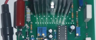
The diagram below allows you to assemble a frequency device for adjusting electric motors with a power of up to 500 W. The rotation speed is changed within the range from 1000 to 4000 rpm.
The device consists of a master oscillator with variable frequency, consisting of a multivibrator assembled on a K561LA7 microcircuit, a counter on a K561IE8 microcircuit, and a half-bridge regulator. Output transformer T1 decouples the upper and lower transistors of the half-bridge.
The damping circuit C4, R7 dampens voltage surges that are dangerous for power transistors VT3, VT4. The rectifier, a supply voltage doubler, includes a VD9 diode bridge, with a filter capacitor on which the half-bridge supply voltage is doubled.
Primary winding voltage: 2×12V, secondary winding 12V. The primary winding of the key control transformer consists of 120 turns of copper wire with a cross-section of 0.7 mm, with a tap from the middle. Secondary - two windings, each with 60 turns of a drive with a cross section of 0.7 mm.
The secondary windings must be insulated from each other as reliably as possible, since the potential difference between them reaches 640 V. The output windings are connected to the switch gates in antiphase.
So we looked at ways to adjust the speed of asynchronous motors. If you have any questions, ask them in the comments below the article!
Single-phase asynchronous motors are powered from a conventional 220 V alternating voltage network.
The most common design of such motors contains two (or more) windings - working and phase-shifting. The working one is fed directly, and the additional one is fed through a capacitor, which shifts the phase by 90 degrees, which creates a rotating magnetic field. Therefore, such motors are also called two-phase or capacitor motors.
It is necessary to regulate the rotation speed of such motors, for example, for:
- changes in air flow in the ventilation system
- pump performance control
- changes in the speed of moving parts, for example in machine tools, conveyors
In ventilation systems, this allows you to save energy, reduce the level of acoustic noise of the installation, and set the required performance.
Methods of regulation
We will not consider mechanical methods of changing the rotation speed, for example gearboxes, couplings, gear transmissions. We will also not touch upon the method of changing the number of poles of the windings.
Let's consider methods with changing electrical parameters:
- change in motor supply voltage
- change in supply voltage frequency
Typical speed controller circuits
There is a wide selection of regulators and frequency converters for asynchronous motors on the market today. However, for the domestic needs of lifting or processing equipment, it is quite possible to calculate and assemble a homemade device on a microcircuit based on thyristors or powerful transistors.
Below is an example of a circuit of a fairly powerful regulator for an asynchronous motor. Due to this, you can achieve smooth control of its operating parameters, reduce energy consumption by up to 50%, and reduce maintenance costs.
This scheme is complex. For domestic needs, it can be significantly simplified by using a triac, for example, VT138-600, as a working element. In this case, the diagram will look like this:
The motor speed will be regulated by a potentiometer, which determines the phase of the input pulse that opens the triac.
As can be judged from the information presented above, not only its operating parameters, but also the efficiency of the powered lifting or processing equipment depend on the speed of an asynchronous motor. Today you can purchase a wide variety of regulators in the retail chain, but you can also make calculations and assemble an effective device with your own hands.
Frequency regulation
Just recently (10 years ago), there were a limited number of frequency controllers for motor speeds on the market, and they were quite expensive. The reason was that there were no cheap high-voltage power transistors and modules.
But developments in the field of solid-state electronics have made it possible to bring power IGBT modules to the market. As a consequence, there is a massive appearance on the market of inverter air conditioners, welding inverters, and frequency converters.
At the moment, frequency conversion is the main way to regulate the power, performance, speed of all devices and mechanisms driven by an electric motor.
However, frequency converters are designed to control three-phase electric motors.
Single-phase motors can be controlled by:
- specialized single-phase inverters
- three-phase inverters with the exception of the capacitor
Converters for single-phase motors
Currently, only one manufacturer announces serial production of a specialized inverter for capacitor motors - INVERTEK DRIVES.
Optidrive E2 model
For stable engine starting and operation, special algorithms are used.
In this case, frequency adjustment is possible upward, but in a limited frequency range, this is prevented by a capacitor installed in the phase-shifting winding circuit, since its resistance directly depends on the frequency of the current:
f - current frequency
C - capacitance of the capacitor
The output stage uses a bridge circuit with four output IGBT transistors:
Optidrive E2 allows you to control the motor without removing the capacitor from the circuit, that is, without changing the motor design - in some models this is quite difficult to do.
Advantages of a specialized frequency converter:
- intelligent motor control
- Stably stable engine operation
- Huge capabilities of modern inverters:
- the ability to control the operation of the engine to maintain certain characteristics (water pressure, air flow, speed under changing load)
- numerous protections (motor and device itself)
- sensor inputs (digital and analogue)
- various outputs
- communication interface (for control, monitoring)
- preset speeds
- PID controller
Disadvantages of using a single-phase inverter:
Using a state of emergency for three-phase motors
A standard frequency converter has a three-phase voltage at its output. When connecting a single-phase motor to it, remove the capacitor from it and connect it according to the diagram below:
The geometric arrangement of the windings relative to each other in the stator of an asynchronous motor is 90°:
The phase shift of the three-phase voltage is -120°, as a consequence of this - the magnetic field will not be circular, but pulsating and its level will be less than with a power supply with a shift of 90°.
In some capacitor motors, the additional winding is made of thinner wire and therefore has a higher resistance.
When operating without a capacitor, this will lead to:
- stronger heating of the winding (service life is reduced, short circuits and interturn short circuits are possible)
- different current in the windings
Many inverters have protection against current asymmetry in the windings; if it is impossible to disable this function in the device, operation using this circuit will be impossible
Advantages:
- lower cost compared to specialized inverters
- Huge selection of power and manufacturers
- wider frequency control range
- all the advantages of the inverter (inputs/outputs, intelligent operating algorithms, communication interfaces)
Disadvantages of the method:
- the need for preliminary selection of the inverter and motor for joint operation
- pulsating and reduced torque
- increased heating
- no warranty in case of failure, because Three-phase inverters are not designed to work with single-phase motors
Quite often, the operating mode of auxiliary mechanized equipment requires a reduction in standard rotation speeds. This effect can be achieved by adjusting the speed of an asynchronous motor. Let's try to figure out how to do this with our own hands (calculation and assembly), using standard control circuits or home-made devices.
- What is an asynchronous motor?
- Squirrel-cage motors (SCR)
- Wound rotor motors
- Operating principle and speed of asynchronous motors
- Ways to change engine speed
- Typical speed controller circuits