The variable-speed induction drive is widespread and popular, so much so that it has virtually replaced synchronous electric motors and DC drives.
Options for adjusting the speed of an electric motor include several existing methods:
- Changing the voltage supply;
- Switching windings of asynchronous motors;
- Frequency control of electric motor speed by changing current values;
- Application of an electronic switch.
This was largely due to the advent of frequency converters that provide energy and dynamic performance. The use of a frequency speed controller is considered the most progressive and popular method included in the methods of adjusting the rotation speed of asynchronous motors.
The main purpose of a frequency speed controller for an asynchronous motor is based on providing power in such a way that the operating characteristics of the unit are radically different from the usual parameters obtained from the network. In this case, the network voltage and frequency must remain unchanged.
Design and principle of operation, structure of the frequency regulator
The operating principle of a frequency regulator for an asynchronous motor is to supply the electric motor with an alternating voltage with amplitude and frequency parameters changing as needed. At the same time, the support voltage/frequency ratio remains clearly defined and unchanged. The generation of alternating voltage occurs thanks to a power electronic converter.
Rice. No. 1 Schematic diagram of the frequency converter.
The operating principle involves the use of pulse width modulation. The principle involves applying a pulse voltage to the motor windings with an amplitude equal to the voltage received from the rectifier. The pulses are width modulated and produce an alternating current voltage with varying amplitude. A good example is the phase-to-phase voltage and current curves in one motor winding when the windings are connected in a triangle.
Rice. No. 2 Graph of the voltage at the PWM output and the current in the motor winding when connecting a three-phase asynchronous motor in a triangle.
What is an asynchronous motor?
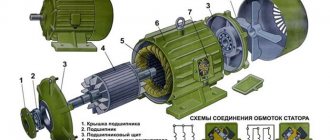
AC electric motors have found quite wide application in various spheres of our life, in hoisting, processing, and measuring equipment. They are used to convert electrical energy that comes from the network into mechanical energy of a rotating shaft. Most often, asynchronous AC converters are used. In them, the rotation speed of the rotor and stator is different. A structural air gap is provided between these active elements.
Both the stator and the rotor have a rigid core made of electrical steel (composited type, made of plates), acting as a magnetic circuit, as well as a winding that fits into the structural grooves of the core. It is the way in which the rotor winding is organized or laid out that is the key criterion for classifying these machines.
Squirrel-cage motors (SCR)
Here, a winding is used in the form of aluminum, copper or brass rods, which are inserted into the grooves of the core and closed on both sides by disks (rings). The type of connection of these elements depends on the engine power: for small values, the method of joint casting of disks and rods is used, and for large values, separate production is used, followed by welding to each other. The stator winding is connected using delta or star circuits.
Wound rotor motors
The three-phase rotor winding is connected to the network via slip rings on the main shaft and brushes. The “star” scheme is taken as the basis. The figure below shows a typical design of such an engine.
The main elements that make up the structure of the frequency converter
The frequency converter consists of the following components:
- A bridge rectifier for 1 or 3 phases, equipped with a capacitor at the output, is a source of constant voltage.
- A bridge inverter (IGBT) is supplied with a constant voltage using the pulse-width modulation method and is used to generate an alternating current voltage with variable amplitude and frequency.
- A control module that provides conductivity commands to the inverter. They depend on the signals supplied by the operator and information about the results of measurements of electrical quantities (mains voltage, motor load current).
Self-production of the device
Despite the many factory-produced units, people make frequency converters on their own, fortunately today all its components can be bought at any radio store or ordered from China. Such a frequency generator will cost you much less than a purchased one, and besides, you will not doubt the quality of its assembly and reliability.
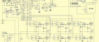
Making a three-phase converter
We will assemble our converter using G4PH50UD mosfets, which will be controlled by a PIC16F628A controller using HCPL3120 optodrivers.
The assembled frequency generator, when connected to a single-phase 220 V network, will have three full phases of 220 V at the output, with a shift of 120°, and a power of 3 kW.
The frequency circuit diagram looks like this:
Since the frequency converter consists of parts operating at both high (power part) and low (control) voltage, it would be logical to split it into three boards (main board, control board, and low-voltage power supply for it) to exclude the possibility of breakdown between tracks with high and low voltage and failure of the device.
This is what the control board layout looks like:
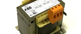
To power the control board, you can use any 24 V power supply, with ripples of no more than 1 V peak-to-peak, with a delay in stopping the power supply for 2-3 seconds from the moment the 220 V supply voltage disappears.
You can assemble the power supply yourself using this diagram:
Please note that the ratings and names of all radio components on the diagrams are already labeled, so even a novice radio amateur can assemble a working device using them.
Before you begin assembling the converter, make sure:
- You have all the necessary components;
- The board layout is correct;
- There are all the necessary holes for installing radio components on the board;
- The fact is that they did not forget to upload the firmware from this archive to the microcontroller:
If you did everything correctly and didn’t forget anything, you can start assembling.
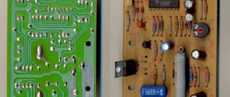
After assembly you will end up with something similar to this:
Now all you have to do is check the device: to do this, connect the motor to the frequency converter and apply voltage to it. After the LED lights up indicating readiness, press the “Start” button. The engine should begin to rotate slowly. When you hold the button, the engine begins to accelerate, and when you release it, it maintains the speed at the level to which it managed to accelerate. When the Reset button is pressed, the engine coasts to a stop. The “Reverse” button is activated only when the engine is stopped.
If the test was successful, then you can begin to manufacture the case and assemble the frequency generator in it. Do not forget to make holes in the housing for the inflow of cold air and the outflow of hot air from the radiator of the IGBT transistors.
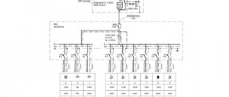
Frequency converter for single-phase motor
A frequency converter for a single-phase motor differs from a three-phase one in that it has two phases at the output (there is no error here, the motor is single-phase, when connected without a frequency converter, the working winding is connected directly to the network, and the starting winding is connected through a capacitor; but when using a frequency converter, the starting winding is connected through the second phase) and one neutral - in contrast to the three phases of the latter, so to make a frequency converter for a single-phase electric motor using a three-phase circuit as a basis, so you will have to start all over again.
We will use an ATmega328 MCU with an Arduino loader as the brain of this converter. In principle, this is Arduino, only without its own harness. So, if you have an Arduino with such a microcontroller lying around in your bins, you can safely unsolder it and use it for business, after uploading the sketch (firmware) from this archive onto it:
The IR2132 driver will be connected to the atmega, and the IRG4BC30 mosfets will be connected to it, to which we will connect a motor with a power of up to 1 kW inclusive.
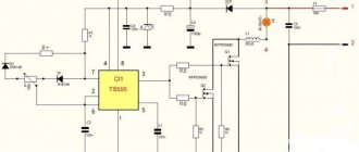
Frequency converter diagram for a single-phase motor:
Also, to power the arduino (5V) and to power the power relay (12V), we will need 2 stabilizers. Here are their diagrams:
12 volt stabilizer.
5 volt stabilizer.
Attention! This scheme is not simple. You may have to configure and debug the firmware to achieve full functionality of the device, but this is not difficult, and there are a lot of Arduino programming manuals on the Internet. In addition, the sketch itself contains quite detailed comments for each action. But if this is too difficult for you, then you can try to find such a frequency generator in a store. Even though they are not as common as frequency converters for three-phase motors, you can buy them, albeit not in every store.
Also pay attention to the fact that you cannot turn on the circuit without ballast - the output switches will burn out. The ballast must be connected through a diode with the anode facing the power filter capacitor. If you connect the ballast without a diode, the keys will fail again.
If you are satisfied with everything, you can start making the board , and then - assembling the entire circuit. Before assembly, make sure that the board layout is correct and there are no defects in it, and also that you have all the radio components indicated in the diagram. Also remember to install the IGBT transistors on a massive heatsink and isolate them from it by using thermal pads and insulating washers.
After assembling the frequency unit, you can start checking it. Ideally, you should have the following functionality: button “S1” - start, each subsequent press adds a certain (changed by editing the sketch) number of revolutions; "S2" is the same as "S1", but makes the motor rotate in the opposite direction; button “S3” - stop; when pressed, the engine coasts to a stop.
Please note that the reverse is carried out through a complete stop of the engine; if you try to change the direction of rotation while the engine is running, it will immediately stop, and the power switches will burn out from overload. If you don't mind the money you have to spend on replacing mosfets, you can use this feature as an emergency brake.
Frequency controller structure
Currently, two main topologies of multilevel frequency converters have been developed in detail and are widely used. These are cascade and converters based on multi-level frequency voltage inverters.
Rice. No. 3 Block diagram of a high-voltage multilevel frequency converter, built on the basis of air- or water-cooled IGBT transistors.
The device includes a multi-winding transformer. Features of the circuit include the presence of power cells with a serial connection, due to which a total high voltage is obtained at the output of the device. Such a circuit serves to obtain an output voltage shape that is almost close to an ideal sine wave. The presence of cells that are shunted at the time of malfunction determines the high reliability of the circuit.
As a continuation of the previous circuit, we will consider a converter circuit based on a transformer multilevel voltage inverter with pulse width modulation using IGBT modules. The device is characterized by a fixed PWM frequency of 3 kHz. The structure of the device includes a protection system using a microprocessor.
Rice. 4 Block diagram of the converter.
The diagram shows that all blocks are functionally interconnected. The diagram shows how a frequency regulator works for an asynchronous motor, its structure and principle of operation.
The first block contains an input transformer; the block transmits electricity from a three-phase high-voltage power source. From the multi-level transformer, the reduced voltage is distributed into the inverter cabinet to the multi-level inverter.
The inverter cabinet includes a multi-level three-phase inverter consisting of converter cells. Each contains a six-pulse filter for rectifying the DC link and a bridge voltage inverter based on IGBT transistors. According to the circuit, the input alternating current is rectified, which, thanks to the inverter, is changed into alternating current with adjustable frequency and voltage.
The control protection cabinet contains a microprocessor unit with multifunctional capabilities and a power supply system from the converter TSN, a converter input device and primary sensors indicating the operating modes of the converter.
The microprocessor is used to generate inverter control signals depending on the designated operating algorithm. It is used to process information collected from voltage and current sensors. The microprocessor generates signals to control protections and emergency control buttons, and adjusts the control algorithm.
Fiber optic cable is used to transmit information and communication. For uninterrupted operation there is an independent built-in power supply. Parameter editing is performed using the remote control.
For reliable shutdown and safe performance of various types of work, the converter is equipped with a linear disconnector.
Rice. No. 5 Generalized diagram of the converter cell
Controlled alternating voltage sources form a voltage phase to perform their series connection. The output circuit of the supply network of an asynchronous motor occurs according to the “Star” winding connection diagram. The voltage in a three-phase inverter is distributed according to the circuit.
Rice. No. 6 Voltage distribution diagram in the inverter into three phases.
Schematic diagram of single-phase blood pressure
An electric motor is a machine that converts electrical energy into mechanical energy, thanks to which mechanisms are set in motion. When converting energy back, these devices act as a generator. The rotor (rotating) and stator (stationary) are the main components of electric motors.
To create a rotating field, two windings on the stator are required, offset in space at a certain angle. The starting unit is placed on the stator in accordance with this with an offset relative to the working one of 90 degrees. To ensure a current shift, when connecting it to the network, a phase-shifting element is used - a coil, capacitor or active resistor.
When current flows through a conductor, a magnetic field is created that acts on it with a force F. If the conductor is bent into a frame and placed in a magnetic field, two sides that are at an angle of 90 degrees to the field will experience the same force, but in the opposite direction , which create torque.
Frequency converters for single-phase asynchronous electric motors
The use of small-sized frequency converters is used to control the rotation speed of single-phase motors used in the design of household devices and for the production of technological processes. For more information about regulating a single-phase asynchronous motor using a frequency converter, see here.
A frequency speed controller for an asynchronous motor will be extremely relevant in control circuits for devices such as air conditioners, refrigerators, electric fans, pumps, and all equipment using asynchronous electric motors.
Purpose and functions of regulators
Not so long ago, devices for adjusting the rotation speed of an asynchronous electric motor consisted of simple manual switches and a magnetic relay, thanks to which it was only possible to start the motor at maximum speed or completely turn it off.
Any engine speed controller, including a frequency controller, is designed to change the engine rotation speed. In this case, the main function of the speed controller is to change the performance of the exhaust system or other equipment. But besides this, such devices also have additional capabilities that should not be forgotten:
- reduction of equipment wear during operation;
- saving consumed electrical energy;
- reduction of noise at maximum speed.
Most devices that regulate the rotation speed of an electric motor can be used as a separate element of the system, or as an addition to an electronic control unit, a household appliance driven by a motor.
Features of using speed controllers for single-phase electric motors
The design of the frequency regulator includes several elements that ensure the efficiency of the device, these include:
- Built-in RS485 interface converter (optional);
- Built-in PLC controller;
- Built-in PID controller (generates a signal to control the device).
The advantageous features of using speed controllers include innovative vector control technologies. Significant energy-saving efficiency is a feature that is provided automatically. The speed controller can be controlled using a remote control, the minimum control distance is 5m.
Important: the design of the frequency converter provides the ability to automatically regulate the output voltage.
How to choose a frequency converter with the help of Vesper specialists
Large manufacturers produce a huge range of emergency products. If you need to take into account many criteria when purchasing, then a good option would be to seek advice from specialists. has extensive experience in carrying out work on the selection of frequency converters for various industrial and household machines and mechanisms.
If you need a frequency converter with additional options to solve specific problems, then this is another reason to contact a large company. For example, this problem is solved by the engineering department, which will recommend and select additional equipment according to the customer’s personal wishes:
- will install the inverter in a housing with the required degree of IP protection and a supply and exhaust ventilation system;
- will retrofit with sensors, counters, timers, filters, chokes, internal power supplies, dynamic braking devices;
The company's specialists are ready to advise on the use of products in various technological processes. Call 8-800-555-36-49 or write to us at [email protected]
Popular models of speed controllers for single-phase motors
Among the variety of devices that perform the function of controlling an electric motor, there are two main types of speed controller models. These are electronic thyristor single-phase speed controllers that operate by smoothly changing the supply voltage. The second type of speed controller models is a transformer single-phase speed controller. Its work is to change the position of a three-stage cam switch, which changes the switching combination of the windings.
Frequency control for speed control of asynchronous electric motors is a technical standard nowadays. The use of a frequency regulator has replaced many control methods. Symmetrical and asymmetrical voltage control and the use of additional resistances, changing the number of pole pairs are a thing of the past.
Frequency generator, frequency converter 220 - 380 motor speed controller
Motor speed control options
To change the rotation speed of both an asynchronous and any other motor, several speed control options are used:
- voltage supply adjustment;
- switching windings of asynchronous multi-speed motors;
- frequency adjustment of current indicators;
- use of an electronic switch.
Changing the voltage makes it possible to use fairly cheap devices for smooth or multi-stage speed control. If we talk about asynchronous motors that have an external rotor, then it is better for them to use an armature resistance regulator to change the speed. At the same time, frequency control allows you to change speed indicators in a fairly wide range.
Self-connection of the converter
Before you start connecting the device, you should use a de-energizing circuit breaker; it will ensure that the entire system is turned off in the event of a short circuit to any of the phases.
There are two schemes for connecting an electric motor to a frequency converter:
- "Triangle".
The diagram is relevant if you need to control a single-phase drive. The power level of the converter in the circuit is up to three kilowatts, and no power is lost.
- "Star".
A method suitable for connecting the terminals of three-phase frequency drives powered by industrial three-phase networks.
The figure shows the connection diagram for the 8400 Vector.
To limit the starting current and reduce the starting torque when starting an electric motor with a power exceeding 5 kW, star-delta switching is used.
When voltage is applied to the stator, the device is connected as a star. As soon as the motor speed begins to correspond to the nominal value, power is supplied according to the “triangle” circuit. But this technique is used only when technical capabilities allow connecting in two circuits.
In a combined star and delta circuit, sharp current surges are observed. When switching to the second type of connection, the rotational speed readings decrease significantly. To restore the previous operating mode and speed, the current should be increased.
Frequency generators are most actively used in the design of an electric motor with a power level of 0.4 - 7.5 kW.
Types of regulators
There are a large number of regulators for single-phase and three-phase motors. Both have their own advantages and disadvantages:
- Thyristor.
- Triac.
- Frequency converters.
Regulators assembled on the basis of thyristors are a pretty good choice. They contain various types of protection: from overheating, voltage surges . The advantages of this type of regulators include a relatively low price, as well as low weight and size. But there are also disadvantages, which include crackling, noise and jerking when starting .
Triac devices are more versatile than thyristor devices. They allow you to control the speed of several motors at once, support operation with both direct and alternating current, and noise manifestations are minimized. The triac regulator is considered one of the most affordable in terms of price and quality.
A frequency controller is used to change the output voltage from 0 to 500V. The higher the output voltage, the higher the speed. This type of adjustment is used for three-phase motors whose voltage is 380 volts - for example, in air conditioning systems, ventilation fans.
If the motor power is high, from 100 to 500 kW, then the transformer type . Thanks to this adjustment, it is possible to smoothly start the electric motor and stepwise change the shaft rotation speed, as well as control several powerful devices at once in automatic mode.
The frequency regulator appeared not so long ago. Since this device was based on expensive power transistors and high voltage modules, the price was unreasonably high. But thanks to the latest developments, the price has dropped significantly, which has made it possible to purchase the device without any problems.
After some time, store shelves were filled with inverter-type welding machines, air conditioners and frequency converters.
At the moment, speed controllers for asynchronous electric motors are in quite high demand. Perhaps this is the best option for adjusting the speed of an asynchronous motor.
Frequency generators assembled on the basis of powerful semiconductor transistors have a direct impact on the rotation speed.
But there is one caveat : as the frequency decreases, the overload capacity also drops, which leads to a decrease in voltage. Therefore, increased voltage must be supplied to the frequency regulator. In this case, everything depends on the design features. If adjustments need to be made on an electric motor whose shaft is subject to an unstable mechanical load, the voltage will increase as the frequency decreases.
If it is necessary to make adjustments on an electric motor with constant power, the voltage increase is proportional to the square root of the frequency drop. A frequency converter is the optimal choice for adjusting the speed of an asynchronous motor.
A frequency converter. Schemes, signets, descriptions and programs.
Self-assembly will require some knowledge and skills. However, unprepared people do not look for such materials. Therefore, we will present two options for frequency converters from well-known and authoritative Internet sources, because their publications can be trusted, for which we thank them.
PS Slang amateur radio expressions are used, but at the same time human-understandable.
So:
Setting up the frequency converter
When setting up the frequency generator, you need to pay attention to the following points:
- If possible, limit the acceleration and deceleration times in order to reduce heating of the drive and the motor. The same applies to the number of on/off cycles per unit of time.
- Select scalar frequency control mode.
- Disable phase loss monitoring at the inverter output.
- Before the first start-up, be sure to carry out automatic configuration (adaptation) according to the instructions.
Here you need to pay attention to one important point. A single-phase motor has lower efficiency than a three-phase motor with the same parameters. This should be taken into account when choosing a drive/motor pair. To increase efficiency and reduce heating, you can experimentally set points on the voltage-frequency graph. Alternatively, you can disconnect the starting capacitor, and connect the leads from the starting and working windings to the output of the three-phase converter. Next, carry out the settings as indicated above.