A laboratory autotransformer is a device that regulates current and voltage over a wide range with a smooth change in parameters. The process is ensured by moving the movable contact along the turns, changing the induction in the winding. The device allows you to generate accurate voltage values and a pure sine wave at the output. The design is characterized by high efficiency, up to 98%, and has smaller dimensions and weight compared to analogues. The autotransformer is used in summer cottages and gardens with a reduced input voltage. Used in laboratories, workshops, for charging batteries, powering consumers with non-standard voltage values.
What is a laboratory autotransformer (LATR)
Very often among electricians and electronics engineers the abbreviation LATR . Remember, we once looked at the power supply and even made it ourselves. The power supply gave us a constant voltage from zero to some final value, which, of course, depended on the steepness of the power supply. Agree, a very convenient thing. But there is one drawback - it only gives us constant voltage .
But, since there is a power supply for constant voltage, then there must be a power supply for alternating voltage . And such a power supply is called a laboratory autotransformer , or LATR . What is this thing and what is it eaten with?
LATR is the same transformer. It converts alternating voltage of one magnitude into alternating voltage of another magnitude . But the trick is that we can change the voltage at the LATR output if necessary.
LATR TDGC2 0.5a – inexpensive and stylish
Compact, with a stylish and impressive body design, autotransformer. It is a type of transformer. The design feature is a direct connection of the primary and secondary windings.
The device provides constant voltage values during manual adjustment. It is used for repairing and setting up electronic equipment, instruments, and testing equipment.
The range of readings is 0~250 volts. Load current up to 2A. Visual control - using the built-in pointer voltmeter.
Pros:
- Price, easy to use.
- Stylish body design, compact size.
- Large comfortable handle, vertical dial arrangement.
Minuses:
- There is no carrying handle - with such a mass you have to use both hands.
- The build quality leaves much to be desired.
Types of LATRs
Single-phase
This type of LATR produces single-phase alternating regulated voltage. It is very often used by radio amateurs, as it allows you to select any low-voltage alternating voltage.
Three-phase
This type of LATR is used in industrial electronics. A three-phase voltage is supplied to its input, and at the output we get the same three phases, but with a smaller amplitude. This LATR allows you to change the voltage amplitude of all three phases simultaneously . Roughly speaking, these are three single-phase LATRs, which are located in the same housing and which change the voltage equally.
Types of autotransformers
Single-phase - can only be used to connect to a single-phase 220 V network. The output voltage adjustment range is from 0 to 300 V.
Three-phase - designed for a 380 V network. They can regulate the output voltage from 0 to 430 V.
Show more ArticlesVideo 02/10/2017 LATR: what is a laboratory autotransformer for? In our country, two types of electrical networks are common - single-phase (with a voltage of 220 V) and three-phase (with a voltage of 380 V). Consequently, most electrical appliances, machinery and equipment are designed to work with such parameters. But they are not suitable for electronics and household appliances imported from the USA or Japan, because in these countries household electrical networks have a voltage of 110 V. What to do, for example, when repairing automotive electronic equipment requires a supply voltage of 12-13 V ? To adjust the voltage there are special devices - transformers. Review: Autotransformer Resanta LATR TDGC2-0.5 Autotransformers LATR Review of laboratory autotransformers SUNTEK
It will be interesting➡ What is active power?
Description of the work of LATRA RESANTA
Let's look at a single-phase LATR manufactured in Latvia RESANTA (read in Russian) brand TDGC2-0.5 kVA.
From above our LATR looks like this:
We see a regulator with which we can set the voltage we need.
On the front side we see some kind of alternating voltage voltmeter. We apply voltage from the 220 V network to the terminals on the left, and from the terminals on the right - the voltage that we currently require.
Principle of operation
The operating principle of a laboratory transformer can be considered using the example of a compact and lightweight model LATR-1M, designed for current up to 9A. The lower the maximum current value, the greater the likelihood of device failure due to burnout. In this case, single-phase LATR provides smooth voltage regulation in the range of 0-250 V without interrupting the electrical circuit.
Wires in different combinations can be connected to six terminals:
- The initial output terminals are B or D, and point B is connected to the regulator. By rotating the handle you can obtain an output voltage within the range of 0-250V. Obtaining the desired value in LATR is ensured by the connection diagram, which must be selected correctly, depending on the input voltage supply.
- The input terminals, designated D and E, are designed for 220V alternating current.
- Output to load in the range 0-250V – through contacts B and C.
- Terminals G and D are provided for an input voltage of 127V.
- With an input voltage of 250V, contacts A and D are activated.
The operating principle of this and other models is to use a transformation ratio that changes its value when the graphite element begins to move along the winding path without insulation during the rotation of the regulator. In the extreme maximum position, instead of 220, 250V is obtained. This difference is provided by additional turns.
A three-phase device operates in exactly the same way. When 127V voltage is applied to inputs A-D, a proportional decrease in scale values occurs. Conversely, if too much current is supplied, the device is likely to fail.
How LATR works in practice
Let's conduct experiments with a 95 Watt 220 Volt incandescent light bulb. To do this, connect it to the output terminals on the right.
I wonder at what voltage the light bulb filament will start to glow? Let's find out! We turn the regulator until we notice a faint glow of the light bulb.
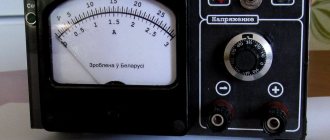
We look at the regulator scale. 35 Volts!
Did you know that in the USA the mains voltage is 110 Volts? I wonder how our light bulb would glow then? We set it to 110 Volts.
It glows, as they say, at full incandescence.
Now compare how it glows at 220 V
There is no point in increasing the voltage further. The light bulb may burn out.
If you want to set the voltage with great accuracy, then, of course, you can’t do without a multimeter. To do this, set the multimeter knob to the AC voltage measuring position.
We cling and measure the alternating voltage. At the same time, we adjust it using the LATR regulator. Exactly 110 Volts!
LATR AOSN 2 220 82 UHL4 - very simple design
Single-phase dry autotransformer for work with radio-electronic equipment. Natural cooling was applied. It is possible to adjust under load. Operates from a network with a nominal value of 220 volts. Frequency – 50/60Hz.
Adjustment range 5~240V. Load current rating is 2A. Connection to the network via power wires and terminals. Operates in continuous current supply mode. High reliability and long service life.
Pros:
- Cost, very simple design, no fancy stuff.
- Reliable, stable performance.
- Convenient display of values using a rotary handle.
Minuses:
- There is no built-in voltmeter.
- Connecting via terminals is an additional waste of time and less electrical safety.
Recommendations: 15 best voltage stabilizers
18 best electric generators
6 Best Welding Generators
Safety precautions when working with LATR
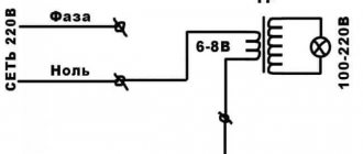
I would also like to add a few words about safety precautions. There are LATRs without galvanic isolation . This means that the phase wire from the network goes directly to the output of such a LATR. The LATR circuit without galvanic isolation looks like this:
In this case, a network voltage of 220 Volts may appear at the output terminal of the LATR with a probability of 50/50. It all depends on how you plug the LATR mains plug into a 220 Volt socket.
If you look closely at the circuit diagram on the front panel of the LATR Resanta, you can see that the “X” and “x” terminals (the two bottom ones) are connected to each other by a conductor.
That is, if there is a phase on the “X” terminal, then there will also be a phase on the “x” terminal! You won’t measure the phase in the socket every time to insert the plug correctly, will you? Therefore, BE extremely CAREFUL! Try not to touch the LATR output terminals with your bare hands!
In principle, I touched it and nothing like that happened to me. The problem turned out to be that I have a wooden floor, which is almost a dielectric. I measured the voltage between me and the phase - about 40 Volts came out. That's why I didn't feel these 40 Volts. If I grabbed the battery with one hand or stood with my bare feet on the ground, and with the other hand grabbed the output “x” of the LATR, then I would be shaken very, very hard, since all the full 220 Volts would pass through me.
LATR RNO 250 0.5 M – double input voltage
Dry free cooling device. Equipped with two inputs - 127 and 220 volts. Used for smooth changes in voltage values when performing various electrical work. Changing output values 0~250 volts, received from any input.
Power up to 0.5 kW. The required values are set using a rotary toggle switch on the vertical cover, equipped with a graduated scale. Connection is via threaded terminals. Quite effective air cooling at peak loads.
Pros:
- Ability to work with two types of input voltages.
- Convenient setting of the required voltage values.
- Inexpensive, easy to use.
Minuses:
- Outdated connection via terminals.
- There is no built-in voltmeter.
Isolation transformer and LATR
There are also safer types of LATRs. They include an isolating transformer . The diagram of such a LATR looks something like this:
As we can see, the phase wire is isolated from the output terminals of such a LATR, thanks to a transformer, the operating principle of which you can read in this article. In this case we may be shaken if we set a high voltage at the output of the LATR using a twister and grab two output wires of the LATR at once. That is, there is a typical galvanic isolation .
Operating modes
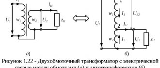
- In autotransformer modes (a), it is possible to transfer rated power from the HV winding to the LV winding or vice versa. In both modes, the series and common windings are loaded with typical power, which is acceptable.
- In transformer modes, it is possible to transfer power from the LV winding to the MV or HV winding, and the LV winding can be loaded to no more than Stype. In these modes, the AT is underloaded, which is acceptable, but uneconomical.
- In combined mode (b), it is possible to transfer power of no more than S type from the LV network to the HV network and at the same time (Snom Stype) by autotransformer from the MV network to the HV network. This mode is acceptable and economical, because the load of the common winding can, in the limit, be equal to 0, and through the AT the total is transmitted Snom.
Also read: Three-phase oil transformer - src=»https://ofaze.ru/wp-content/uploads/2019/10/rezhimy-raboty.jpg» class=»aligncenter» width=»900″ height=»293″[ /img]
Selecting the optimal operating mode is important for three-phase devices. They are used for continuous parameter adjustment with low losses. This component provides users with the best possible adjustment accuracy with minimal losses and therefore reduced heat generation. For three-phase current, this effect is achieved using mechanical connections of three control transformers. The sliding current collectors are designed in such a way as to ensure reliable output contact and, when triggered, simultaneous cleaning of the contact track. Carbon brushes are used that can rotate or move back and forth.
A variable autotransformer has multiple primary windings to create a secondary voltage that is regulated in the range of a few volts to fractions of volts per revolution. This is achieved by placing a carbon brush or slider in contact with one or more turns of the primary winding. Since the turns of the primary coil are evenly distributed along its length, the output value is proportional to the angular rotation of the brush.