Glossary
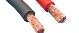
LED strip, SDL – LED strip.
RGB strip is a multi-colored LED strip.
LED element, crystal, LED - light-emitting diode (diode).
A resistor is an element of an electrical circuit that limits the operating electric current.
Dielectric is a material that does not conduct electric current.
A soldering iron is a tool designed for soldering and tinning when heated.
The tip is the tip of a soldering iron that applies solder.
Pole is a certain side (direction) of a constant current source, “plus” and “minus”.
Stripper is a hand-held tool for stripping cable insulation.
Rosin, flux, is a substance that cleans the surface from oxidation.
Solder is a substance used for soldering.
Tinning is the process of covering a work surface with a thin layer of solder.
A connector is a device for connecting sections of an LED strip to each other, without solder.
How to fix an LED strip on a wall - Construction and repair
LED strip can be used in different ways. Depending on the features, installation is also carried out. LEDs are often used as lighting for sinks. The peculiarity is that it is prohibited to use 220 V lighting in such areas. At least closer than at a height of a couple of meters.
Due to this, normal light cannot be installed under the second level of the set hung on the walls of the kitchen. And LEDs are powered by 12 V, which automatically puts them in the highest class of electrical safety. These devices can already be used even for lighting a jacuzzi.
But today we will show you how to install an LED strip on the ceiling.
Where to install LED strip on a suspended ceiling
More often, PVC ceilings are equipped with lighting. The mentioned subtype of polymer is thin and durable. It is enough to look at how roughly the edge of the canvas is pushed into the clip during installation to understand this truth. In addition, PVC on the ceiling is usually heat-shrinkable:
A hair dryer is used to smooth out minor defects.
With great care, the master guides along the border to rid the eye of unevenness. Due to the complex procedure performed, the PVC ceiling cannot be dismantled.
This means that you will not be able to access the LED strip located above the canvas.
Consequently, ceiling lighting is used in selected cases
This means that you will not be able to access the LED strip located above the canvas. Consequently, ceiling lighting is used in selected cases.
Ceiling lighting options
Armstrong ceiling
It is allowed to be equipped with transparent plastic plates. Lamps are often placed above these. All this is beautifully furnished, transparent tiles form inclusions, or a pattern is created, depending on the designer’s imagination. In our case, the rafters for installing the slabs can be used as a frame supporting the LED strip. You may have to cut it into pieces, we’ll tell you the technology later.
PVC ceilings
They are not always placed on clips. Sometimes it is possible to cut out the canvas and attach a harpoon around the perimeter. The ceiling is attached to a special profile (for the previous case, a similar one is used - “clothespin”), into which it is hammered around the perimeter. As a result, the structure is removable, and the tension is obtained due to the strong joining of the harpoon. It closes at the bottom with a narrow decorative profile.
The system for installing a PVC ceiling on a glazing bead differs in that a specially shaped plastic board is hammered into the starting profile around the perimeter. You will have to work together, but you can flexibly adjust the tension of the ceiling.
Installation recommendations
The three listed systems - in addition to the extravagant ones - are suitable for symbiosis with LED strips. In this case, the lighting is pulled higher and usually goes along the perimeter.
For Armstrong ceilings, the guide profile (let's call it stringers) is made of aluminum, and for PVC sheets, mainly plastic is used. But some craftsmen make an exception to the rule: they attach a flexible edging along the perimeter of the canvas and push it between the wall and the guide.
The LED strip is installed along the inner edge of the profile, the backlight is located above the ceiling (see figure).
Installation diagram
The profile is usually attached to the wall with dowels and nails, not reaching the ceiling. Lighting is installed in the resulting space. An LED strip is glued to the end of the profile. Usually supplied on the reverse side with anti-adhesive tape. You need to carefully remove the protective layer, and there will be glue underneath. The installation method varies, aluminum will serve as an excellent radiator for our lighting, removing heat. A nuance noted:
If trouble happens, seal the hole with masking tape, and to strengthen it on the profile, use a glue gun (a heated muzzle with a trigger and cartridges made of abietine resin and vinyl acetate). A similar thing is done at the junctions of two LED strips. In the indicated location there are contact pads for the wires of the adapter or power supply.
The conductive layer will need to be sealed with masking tape (only if necessary), and then use a glue gun.
Please note that you do not need to solder the LED strip at the joints if you are simply assembling a continuation of the branch. In this place of the LED strip there are contact pads. They are needed to connect the power supply
They are needed to connect the power supply.
Usually a small cable with a connector is soldered into which the cable is connected, but it is permissible directly, large voltages are not expected. To connect LED strips to each other, simply insert one into the other. The contact density is checked simply - you have to ring the entire section.
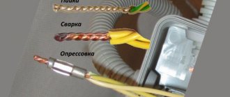
What and where to solder in the LED strip
LED strip (LED) is a light-emitting electrical structure in the form of a flexible printed circuit board (tape) with light sources evenly applied to it - light-emitting diodes (LED) and electric current limiters - resistors (resistors).
When is soldering needed? Example: when contour lighting a ceiling, it is necessary to lay the SDL at a right angle. Despite the flexibility of the board, an ideal right angle can only be achieved by connecting its two parts. Therefore, it is cut into 2 parts in a place specially designated for this purpose, so as not to break the connection diagram of the crystals.
SDL cut location
After this, work on connecting the SDL begins. The complexity of the soldering process depends on the type (single-color, multi-color), type (open, sealed) of the tape, the number of current-carrying paths, and the use of additional devices.
What you need to know
Do not connect with a drop of solder - it is quite fragile and will burst at the slightest deformation. The butt connection can be made with a piece of wire. In the photo, two pieces of tape are soldered with a thin wire, similar to the one in twisted pair.
There is a more exotic soldering option, in which two strips are soldered overlapping . The tape is stripped on both sides, and then the bottom contact track of one piece is joined to the heel of the other.
The soldering option described above is a bad solution. Firstly, the connection is fragile and not reinforced in any way. Secondly, during through soldering, the tape gets very hot, which can lead to its failure.
It is preferable to use soldering, as it is cheaper and provides reliable contact, but it is faster to use connectors. They will help save time during installation and subsequent repairs of large decorative or lighting LED systems!
If you have your own solutions for connecting tapes, share them in the comments and we’ll discuss them.
Finally, an example of different types of connections in the video:
Please rate the article. We tried our best:)
Did you like the article? Tell us about her! You will help us a lot :)
How to solder together
It is possible to solder two sections of tape together (to build up) in two ways:
- Using connecting wires. Each line connects equivalent contacts of two boards (plus with plus, minus with minus).
- Overlapping connection. The connection occurs by overlapping sections on top of each other and soldering them at the contact pads.
- If the SDL is long, it is connected in parallel to the common bus using connecting cables.
Soldering wires to tape
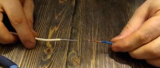
- Clean the ends of the connecting wires using a utility knife or stripper. Tighten the exposed (bare) parts slightly.
Stripped connecting wire
- Tin open ends. Solder is taken to the end of the soldering iron. The end of the cable is dipped in rosin and then solder is applied with a soldering iron. For uniform coverage, the process is repeated 3-4 times.
The process of tying up ends
The length of the cable (up to 2-3 mm) is selected so that its bare ends lie exactly in the “cups” of the contact group. An end that is too long can cause the plus and minus contacts to short out.
- Tin the contact pads of the LED strip:
- Use the end of a toothpick to apply flux to the contact pads.
Applying flux to contact pads (nickels)
- Using a heated soldering iron, apply solder to the contacts by briefly pressing (up to 2 seconds). The maximum contact time between the SDL and the soldering iron is 5 seconds. It is important not to short-circuit the contacts when applying solder.
Applying solder to pads
- Solder the connecting wire to the SDL. Its end is applied to the contact pad of the board. Then, with a short, gentle pressure, solder is applied from above with the tip of a soldering iron.
Due to the high temperature, the tin melts and the wire sinks into the contact “cup,” thereby guaranteeing a reliable connection protected from oxide.
Solder the connecting wire to the SDL
- Solder the second wire in the same way.
Solder the second connecting wire to the SDL
Options for using tape
Strip lighting devices can be used for various purposes - from creating hidden lighting to full-fledged street lighting. Below we will look at each application option in more detail.
For general lighting
Options for using the strip
LED strip is ideal for creating general room lighting instead of conventional incandescent lamps. The best option would be to use devices of class 5050/5055/5060 with a large number of diodes (50-100 pieces), which will evenly illuminate the room. In public institutions, more powerful devices of the 2835 class should be used, since the light from low-power 5050 diodes will be highly scattered.
Note! When choosing a device, pay attention not only to the level of luminous flux, but also the quality of dust protection, the number of diodes and other technical parameters.
For decorative complex lighting
For decorative complex lighting
For decorative complex lighting, long strips with a low level of luminous flux (3528, 5050, 5055, 5060) are suitable. With their help you can create both open and closed lighting. You can decorate any object - mirror, furniture, home appliances, and so on. You can also decorate public institutions - for example, a bar, cafe or nightclub, but in this case you need to use devices with an average level of luminous flux (the best option is 2835).
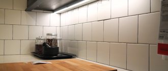
To illuminate the work area
For the work area
Various spaces can be used as a work area - for example, a kitchen, a mirror, a bathroom, and so on. To illuminate the work area, devices of the 5050/5055/5060 class with a dense arrangement of LED lamps are suitable. Devices of this type must have a built-in dimmer, with which you can adjust the brightness of the installation. Also pay attention to the level of protection against dust and water - it should be medium or high.
For street lighting
For street lighting
To create full-fledged street lighting, powerful systems of classes 2835 or 5630/5730 are suitable. They will be able to create a bright, stable light that will be visible from afar. When choosing a device, also pay attention to the quality of protection - it should be at the IP 65/68 level, and if you use weakly protected devices, the backlight will quickly deteriorate and become unusable.
Overlapping connection without wires
- Tin the contacts of one of the tapes on both sides:
- remove the required distance (up to 2-3 cm) of the adhesive base from the back of the board;
- clean the back surface of glue;
- tin the contact pads on the working and opposite sides of the board.
The process of sealing contacts when connecting a board with an overlap
- tin the contacts of the second tape on the working side.
- Place the “back contacts” of the first tape on the contacts of the second tape located on the work surface.
The process of connecting two boards with an overlap (step 1)
- The upper contacts of the first tape, which should be on top of the structure, are heated with a soldering iron. The holding time of the soldering iron in this case is longer (4-5 seconds), because it is necessary to melt both boards together.
The process of connecting two boards with an overlap (step 2)
This connection is not reliable. It is better to use connecting cables.
Soldering silicone coated tape
- Stripping the tape from silicone insulation.
Using a utility knife, cut the silicone across the board at a short distance from the contact group. The cut should not be deep so as not to damage the current-carrying path.
Break the cut area and remove a piece of silicone.
The process of cleaning SDL from silicone
- Consistently repeat the process of “soldering wires to tape” or “overlapping connection without wires.”
- If the SDL protection level requires a silicone coating, it is necessary to restore the protection using heat-shrinkable tubing, silicone or glue.
Connection to power supply or controller
Typically, a 12 V power supply (controller) is used to operate LED strips. Factory power supplies, as a rule, already have a connector for connection. In most cases, such connectors are connected without soldering using the technique described above.
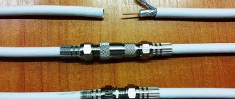
If you need to connect LED strips to a power supply without a connector, you must make your own wires for the connection.
For this you need:
- Wires of the required length;
- Power connector with screw terminals (if the power supply does not have a built-in one);
- Connector for connecting the block to the tape.
Manufacturing and connection procedure:
- Place the ends of the wires into the connector and snap the cover tightly. In some cases, you need to use pliers for crimping.
- Strip the ends of the wires from insulation and insert them evenly into the holes of the power connector. Next, you need to secure the wires with screw clamps, holding them tightly to prevent displacement.
- Connect the manufactured cable to the LED strip, observing the polarity.
For parallel connection, it is advisable to use a special controller. If the tape already has wires for connection, it is enough to connect them to the power supply, observing the polarity, using screw terminals or soldering.
Soldering wires at an angle
This scheme is used when it is necessary to connect sections of SDL in parallel to a common supply bus.
Parallel connection of SDL sections
Figure 104 - example of parallel connection of SDL sections
When connecting the cables in series to the ends of the board module and then bending them towards the bus, the distance between the sections of the tapes increases, which will not look aesthetically pleasing during its operation.
Conventional diagram of parallel connection of SDL sections when connecting cable lines in series to the ends of the module
To do this, solder the wires at an angle:
- The wire is soldered at right angles to the contact, which is located closer to the power bus.
Solder at an angle (step 1)
- When connecting the second cable in the same way, the current-carrying parts overlap, which can lead to the contacts closing together.
Solder at an angle (wrong location)
To avoid a short circuit, the second wire is soldered to a contact that was located on the board earlier and belongs to the same group of diodes.
Solder at an angle (step 2)
Connection technique using connectors
Among the advantages of LED devices, one of the main places is their optimization, which is also reflected in the minimum requirements for consumables during installation. Nevertheless, sometimes the inclusion of connectors in electrical circuits justifies itself. How to solder LEDs with such elements? Soldering in this case acts as an auxiliary means of ensuring a reliable connection between the wires, and the connectors form a kind of reinforcing internal frame. The optimal width of the connector is 8-10 mm. At the first stage, it is necessary to create a structural connection by making the required number of contacts on the board, and then proceed directly to soldering.
It should be taken into account that a connection to a connector does not always provide an advantage from the point of view of future operation of the LED. Firstly, connection points with such fittings are more prone to burning, and also contribute to the rapid heating of the emitter. Secondly, the glow may deteriorate, which is reflected in a decrease in brightness. How to solder LEDs onto a board with a connector to eliminate such negative effects? It is advisable to abandon copper conductors and perform the soldering itself in a continuous manner, which will eliminate the risk of the formation of oxidation sites.
LED RGB strip
The peculiarity of RGB tape is the contacts located close to each other. When carrying out work on wiring contacts, care must be taken not to close them together with tin tracks due to the short distance.
To do this, use the following methods to reduce the area of the tip (tip) of a soldering iron:
- Sharpen the existing tip using a file. The process is labor-intensive and not rational, because the tip will be damaged and may not be suitable for other jobs.
- Self-production of a tip from a copper cable core with a cross-section of 1-2 mm. Such a tip is attached to the main structure with a bolted connection or a collet connector, depending on the modification of the soldering iron.
A small area of the core will allow you to apply tin more accurately and accurately, but it can lead to rapid overheating of the device.
- Purchase ready-made tips of the required shape and cross-section. If you frequently solder SDLs, this is the most profitable method.
RGB LED strip contact strip
For parallel connection of SDL, each cable is also soldered at an angle to one contact on the module.
How to connect with a soldering iron
Soldering connections require some skill with a soldering iron. If you've never done this before, you'll first want to solder a couple of pieces of LED strip together while sitting at your desk. For soldering you will need solder, liquid or solid flux (rosin), a soldering iron and pieces of wire of the required length and color. You will need small pieces of heat shrink tubing to protect the solder joints.
In principle, the solder can be anything, but it is much more convenient to use tubular solder with a small diameter flux. As a liquid flux, it is better to use non-aggressive fluxes that do not require rinsing after soldering. If you use aggressive fluxes and do not wash them off, the solder joints will subsequently corrode and the tape may fail. Rosin does not require rinsing, but it is not very convenient in “field” conditions.
As for the soldering iron, soldering does not require a high-power soldering iron, since the contact pads have a small area, and the cross-section of the soldered conductors usually does not exceed 0.75 - 1.5 mm. Therefore, for soldering you can use a soldering iron with a power of 25 - 40 W.
Before soldering, first thoroughly clean the contact pads and remove the insulation from the conductors to a length corresponding to the size of the pad. After this, flux is applied to the ends of the wire and contacts and they are carefully tinned. Then the wires are soldered. It is advisable to do tinning and soldering quickly so as not to overheat the printed conductors and damage the tape.
After soldering is completed, a small piece of heat-shrinkable tubing is placed over the joint and heated. To heat the heat shrink, it is better to use an electric hair dryer, however, with some skill, the operation can be performed using a gas lighter or the same soldering iron. Once heated, the tube will tightly grip the soldering area and seal the electrical connection.
Common mistakes when soldering LED strips
- Heating the soldering iron above 250 - 300 0C.
High temperatures will cause the contacts to overheat and peel off from the board. You can determine the high temperature of a soldering iron tip in the absence of a regulator by the following signs:
- smoke coming from a soldering iron;
- when the tip is dipped into rosin/flux, it boils;
- poor solder connection to the tip;
- black carbon deposits on the soldering iron tip;
- the surface of the solder on the soldering iron tip is loose and matte (there should be a silvery sheen).
- Use of soldering acid and/or active flux
One of the negative properties of acid is the erosion of the area around the contact group.
Active flux has a long reaction (interaction with metal occurs even after soldering), and therefore requires rinsing off.
This has a negative effect on the contact group and can lead to disruption of its conductive properties.
- Use of low-quality LED strips.
Often, counterfeit SDLs use non-copper alloys that are not soldered.
- The use of rigid multi-core cables that do not have reliable solder fixation.
You need a tape of more than 5 meters. What should I do?
It was said above that LED strips cannot be connected so that their length exceeds 5 m. But there was a caveat: “when connected in series.”
As you know from a school physics course, parallel and series connections have different characteristics in terms of their influence on electrical quantities.
Do-it-yourself safe wiring in a bathhouse - step-by-step instructions- How to choose a phase meter - review, purpose, principle of operation, scope of application + instructions for use with photos
How to make a transformer with your own hands - step-by-step instructions, diagram, drawings, list of materials + photo of a finished homemade transformer
We are interested in the current strength, which, when connected in series, increases to values for which the conductive cores in the diode strips are not designed.
Thus, if you need a long length of tape, you should connect the pieces in parallel, that is, attach the beginning of one piece to the beginning of the next, and the end of the first to the end of the second.
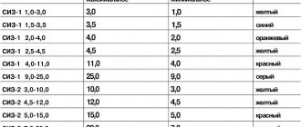
Tip: The long wires that may be required for this connection have high resistance, so it is better to use a double gauge wire (1.5 mm).
Connection methods: soldered, connector and clips
- Soldering involves using solder and heating it under the high temperature of a soldering iron to firmly connect the contacts to each other or to the cable.
Soldering is the most reliable method, and the tin-lead composition protects exposed conductive parts from oxidation and overheating.
Its disadvantage is its low mechanical strength; for this purpose, the solder area is protected with heat-shrinkable tubing or silicone.
- Clips. SDL sections are connected sequentially into only one line. The device consists of a small box with metal conductive clamps, which are installed to equivalent contacts of the modules and clamp them together.
- A connector is a device designed to connect sections of SDL to each other without the use of soldering.
Connector example
Connectors can be with or without connecting wires (for overlapping connections), various shapes of connectors (T-shaped, angular, straight).
Types of connectors
Varieties by number of contacts
The number of contacts in the connector directly depends on the type of LED strips used and can vary from 2 to 6:
- 2 – for monochrome (one-color) stripes.
- 3 – for WS tapes (with the option of cold or warm white glow).
- 4 – for three-color RGB LED strips.
- 5 – for RGBW tapes.
- 6 – for RGBWW or RGBDW stripes.
For information! Currently, you can easily purchase connectors with any number of contacts (from the above) in any geometric design (straight, L-shaped, T-shaped, cross-shaped and with a flexible connection) with various fixation methods, not only for indoor use, but also outside, that is, having an increased degree of protection (IP65).
Connector or solder?
- The connector is convenient in the following cases:
- when soldering is not possible. For example, when assembling SDL directly under the ceiling. Soldering by weight is a dangerous activity, which can lead to burns as a result of dripping solder and damage (burn-through) of the ceiling covering.
- When changing design. The SDL is easily disassembled into sections and assembled according to the required sketch, thanks to the variety of connectors.
- When working with moisture-proof tape, it is recommended to use soldering, because it provides complete protection and insulation from moisture.
- Related Posts
- Decorative neon lamp 220 V: principle of operation, characteristics, how to connect
- Antibacterial (bactericidal) lamp: beneficial and negative properties
- Light sources and what they are
Discussion: 2 comments
- Oleg:
Thank you for the information provided. By the way, who knows where is the best place to buy a New Year's garland? With just over a month left until the New Year, it’s time to think about decorations in the house