Emergency lighting
The presence of artificial lighting at large production facilities and in crowded places is necessary to save people's lives. Therefore, in situations where the power system fails (accident, fire), the emergency lighting system (ELS) is activated.
SAO is not a backup lighting that is activated in the absence of the main one. This is a separate independent system that functions when the main and backup power sources fail.
The power source for emergency lighting lamps is independent autonomous equipment (a generator station or battery that receives “recharging” energy from the main power supply circuit). The entire system operates automatically using an electronic unit or control panel, which transmits a signal to supply voltage to the automatic control system in the event of a malfunction of the main circuit.
The task of the system is to safely evacuate people/personnel to the exit, and also, in case of production necessity, to create conditions for the continuation or completion of the work process.
Part of the emergency lighting system (ELS)
Contents
Normative base
The proper functioning of the emergency control system is vital for people in emergency situations. Therefore, every step, from the design stage to installation work, is regulated by a set of rules and standards, which are described in more detail below.
Basic requirements and standards
The list of main regulatory documents is presented in the table:
| Title of the document | Brief description/link to current resource |
| PUE-7 dated 01/01/2003 | Rules for electrical installations. Edition 7. The book describes the basic rules for the design, installation and operation of electrical installations. https://en-res.ru/wp-content/uploads/2020/02/pue.pdf |
| SP 52.13330.2016 dated 05/08/2017 Updated version of SNiP 23-25-95 | A set of rules regulating the regulatory values of artificial and natural lighting of buildings, structures, and production sites. https://docs.cntd.ru/document/456054197 |
| Federal Law of the Russian Federation No. 123 dated July 22, 2008. (last edition dated December 27, 2018) | Federal Law of the Russian Federation “Technical Regulations on Fire Safety Requirements”. https://www.consultant.ru/document/cons_doc_LAW_78699 |
| GOST R 55842-2013 dated 01/01/2015 | National standard of the Russian Federation. Emergency lighting. Classification and norms. https://docs.cntd.ru/document/1200107497 |
| Federal Law of the Russian Federation No. 384 dated December 30, 2009. (last edition dated 07/02/2013) | Federal Law of the Russian Federation “Technical Regulations on the Safety of Buildings and Structures” https://www.consultant.ru/document/cons_doc_LAW_95720 |
| SP 31-110-2003 | Set of rules. Set of rules for design and construction. Design and installation of electrical installations of residential and public buildings. https://docs.cntd.ru/document/1200035252 |
| SP 3.13130.2009 | Set of rules. Fire protection systems. Warning and management system for evacuation of people in case of fire. Fire safety requirements. https://docs.cntd.ru/document/1200071145 |
| SP 6.13130.2013 | Set of rules. Fire protection systems. Electrical equipment. Fire safety requirements. https://docs.cntd.ru/document/1200100259 |
| SP 52.13330.2016 | Set of rules. Natural and artificial lighting. https://docs.cntd.ru/document/456054197 |
| GOST R 50571.29-2009 (IEC 60364-5-55:2008) | National standard of the Russian Federation. Electrical installations of buildings. Part 5-55. Selection and installation of electrical equipment. Other equipment. https://docs.cntd.ru/document/1200072903 |
| GOST 1ES 60598-2-22-2012 | National standard of the Russian Federation. Lamps. Private requirements. Lamps for emergency lighting. https://docs.cntd.ru/document/1200097788 |
| GOST R 50571.5.56-2013 IEC 60364-5-56:2009 | National standard of the Russian Federation Low-voltage electrical installations. Part 5-56. Selection and installation of electrical equipment. Security systems." Date of introduction: 01/01/2015. https://docs.cntd.ru/document/1200105243 |
| GOST R 51514-2013 (IEC:61547:2009) | National standard of the Russian Federation. Electromagnetic compatibility of technical equipment. Resistance of general-purpose lighting equipment to electromagnetic interference. Requirements and test methods. Date of introduction – 01/01/2014. https://docs.cntd.ru/document/1200104773 |
| GOST 12.4.026-2015 | Interstate standard. System of occupational safety standards. Signal colors, safety signs and signal markings. Purpose and rules of use. General technical requirements and characteristics. Test methods. Date of introduction – 03/01/2017. https://docs.cntd.ru/document/1200136061 |
| TR TS 004/2011 | Technical regulations of the customs union. On the safety of low-voltage equipment. Date of introduction – 08/16/2011. https://docs.cntd.ru/document/902299536 |
Basic requirements for the selection and installation of emergency lighting systems:
- power is supplied from an autonomous independent power source (Federal Law No. 384, Article 2, Part 2.1; SP 52.13330.2016 clause 7.6.1);
- turning on the self-propelled gun - automatically or manually (Federal Law No. 384, Art. 2, Part 2.1; SP 52.13330.2016, Clause 7.6.1);
- voltage is supplied to the emergency network in such a way that 5 seconds after the working lighting is turned off, the normalized illumination value of the object is more than 50%, after 10 seconds - 100% (SP 52.13330.2016 clause 7.6.7, table 7.28);
- operating time - less than 1 hour (SP 52.13330.2016 clause 7.6.10);
- EAS must be configured to work in conjunction with fire safety devices (illumination of signs and panels) (Federal Law No. 384, Art. 2, Part 2.1).
Emergency lighting requirements
Requirements for installation and selection of lamps should be made in accordance with the following requirements:
- the norm of illumination indoors is at least 0.5 lux, in open areas - at least 0.2 lux (SP 52.13330.2016 clause 7.6.7, table 7.28);
- the unevenness of the light flux along the trajectory of movement (escape route) is 40/1 (the ratio of the illumination value at the most illuminated point to its lowest value) (SP 52.13330.2016 clause 7.6.2).
Requirements for installing evacuation signs:
- are established in the following cases (SP 52.13330.2016 clause 7.6.9):
- production premises with an area of more than 150 sq.m;
- presence of more than 100 people in the building;
- a room without natural light, in which there are more than 50 people;
- signs may have their own lighting system from an autonomous power source, or they may be illuminated by emergency lighting fixtures (SP 52.13330.2016 clause 7.6.10);
- Continuous lighting of indicators from working lighting is allowed;
- the distance between signs is at least 25 meters;
- in places of turns, entrances/exits, and junctions of other rooms, additional evacuation signs are installed (SP 52.13330.2016 clause 7.6.9);
- the overall dimensions of the signs must ensure their 100% visibility (SP 52.13330.2016 clause 7.6.10).
The rules for the design of electrical installations (Chapter 6.1 PUE-7) prescribe the classification of emergency lighting, categories of lamps, signs, their power sources and connection diagrams to the power supply network.
How to install
Anyone can make emergency lighting in their own home with their own hands. To do this, you need not only to adhere to the above rules, recommendations and requirements, but also to carry out the installation correctly. Before proceeding with installation, you need to select the required luminaire models. They should produce white light and have a small power of 12 volts. These are the basic requirements for lamps intended for emergency operation.
Low-power emergency lamp
The installation itself here is carried out on a principle similar to the installation of any type of lighting fixture. With the exception of the following nuances:
- evacuation and central lighting must be installed in parallel. Under no circumstances should they be combined;
- The laying of lines here should also be done separately, and not at the location of the main electrical wiring. This will simplify system functionality checks;
- lamps can be equipped with their own battery (as shown in the diagram above), or without it. In the latter case, the emergency lighting will be powered from a common battery. In this regard, it is better to use low-power 12-volt lamps;
- control (remote or manual) of the lighting system must be carried out from the room itself. In this case, only maintenance personnel should have access to the controls. Very often this system can be controlled through an electrical panel. The most effective control method is remote;
Note! In this regard, the corridors should not have buttons with which you can turn on and off the emergency lights.
Electrical panel with emergency lighting control
- installation must provide access for service personnel to all elements of the system. High-quality maintenance of lamps (12 volts) will ensure their trouble-free operation, even in emergency situations for which they are designed. Therefore, it is necessary to regularly engage in testing issues, including checking the functionality of lighting installations and communication networks.
Today, many people prefer remote control. A special device (for example, TELEMANDO) will allow you to achieve such control of 12-volt lamps. Control over the system when installing such equipment will be achieved by disabling the emergency mode when it is not needed. Using such a device, you can effectively troubleshoot problems if they occur. This device allows you to save battery power to which the lighting devices are connected. The device itself has built-in batteries, as well as a return on-off switch. TELEMANDO should be installed in a distribution cabinet on a DIN rail.
Categories of emergency lighting consumers
According to the categories established by the rules (PUE-7 clause 1.2.18), the following are distinguished:
First category. Objects of special strategic importance. The personnel located at this facility are directly involved in maintaining state security. In this case, emergency lighting should be lined up at the level of the main one.
Second category. Objects whose downtime leads to massive disruptions in production technology, defects and, as a consequence, losses. They also have a negative impact on businesses that interact with them. CAO is similar to the first category.
Third category. At such facilities, a lack of electrical energy is allowed for up to 24 hours. Emergency lighting is started from autonomous power sources (diesel generator, batteries) to ensure uninterrupted evacuation of personnel.
Performing a check
The occurrence of an emergency situation is a rare event. However, legislation requires that such equipment be in good working order at all times. To do this, it is necessary not only to install it correctly, but also to regularly check the functionality of the system.
When installing emergency lighting, you need to connect the system being tested to a separate switchboard or through one or a group of circuit breakers to the main switchboard. If this is done in a different way, the inspector will record a violation, which will be included in the inspection report.
Emergency lighting panel Source sigmatek.by
Sometimes such a network belongs to the lessor. In such a situation, the tenant's inspection should not consider the correctness of its connection.
During the verification process, the main network machine is turned off or on, which simulates the occurrence of an emergency. In this case, the emergency lighting must demonstrate its functionality.
Emergency lighting of a substation Source ampervolt.kz
Then the main network is launched. As a result, the emergency system should stop working. Based on the results of the inspection, an act is drawn up, which should reflect the results. In particular, it records the number of lamps, indicating the number of working ones, as well as non-working ones. Regarding the latter, an additional check is performed to determine the cause of the malfunction. It includes the following steps:
- Checking the presence of zero and phase at the corresponding terminals.
- The serviceability of the lamp is monitored. If it doesn't work, it needs to be replaced.
In some cases, the emergency lighting network is not separated. In this case, the main lighting is turned off to check. In this case, emergency lamps should work normally. However, the fact of the absence of a backup line is recorded, which is reflected in the documents.
Lighting in a large store Source specteh-krasnodar.speczakaz.info
Emergency lighting classification
Emergency lighting is classified (SP 52.13330.2016 clause 7.6.1) according to the following scheme
Emergency lighting classification
Reserve
Emergency backup lighting (SP 52.13330.2016 clause 7.6.6) is clearly highlighted as a separate branch and has a different function from evacuation lighting. This is the replacement of the main (working) lighting when the latter fails or during its planned shutdown (for example, periodic repair work).
The duration of operation of the backup line is not limited, i.e. it operates until the main line is restored to working order. Therefore, the technical and operational characteristics of the reserve are aligned with those of the workers.
The working and backup lines are powered by two independent power sources, and the rest of the “lighting circuit” is common. The principle of operation of such a scheme is simple: when the main line is extinguished, a backup source is automatically switched on, which supplies voltage to the same lamps as the main one. Implementing backup lighting on individual lighting sources is neither practical nor profitable.
However, its presence does not exclude the installation of evacuation lighting devices.
The presence of backup lighting is necessary in places of continuous production - factories, train stations, airports, hospitals. However, it is mandatory for kindergartens and schools and does not depend on the number of people in the building.
Evacuation
Emergency evacuation lighting consists of lighting high-risk areas and evacuation routes, taking into account the system for indicating them.
Lighting of high-risk areas (SP 52.13330.2016 clause 7.6.5) protects personnel from dangers when working at height and with specialized vehicles (area of loading and unloading mechanisms, unfenced areas) and technological processes (factory machines, tanks with chemical liquids, exposed conductive parts).
In the event that it is impossible to stop the production process in the specified zone, lighting is implemented in the same circuit as the backup one.
Lighting of high-risk areas (continuous production)
The task of lighting evacuation routes (SP 52.13330.2016 clause 7.6.3) is the safe evacuation of people. Evacuation route devices are located along the entire route, from the first exit from the place of work/residence to the exit from the building.
Lamps and signs are backlit with schematic, readable information signs (directional arrow, pharmacy cross, fire hydrant).
Evacuation route lighting
Anti-panic
The task of anti-panic lighting (SP 52.13330.2016 clause 7.6.4) is to minimize the state of panic among people in the event of an accident and ensure the visibility of evacuation signs from any point.
The readability of information signs and guaranteed illumination help direct people’s actions to the evacuation site without the onset of panic.
It must be installed in indoor and outdoor areas with an area of more than 60 sq.m., as well as when the evacuation plan from the site is difficult.
Operating conditions of anti-panic lighting
General principles and structure
Emergency lighting plays a key role in emergency rescues and the continuation of critical operations. Quickly leaving the premises, neutralizing a chain of technological accidents - all this is possible only with the help of special lighting systems connected to backup energy sources.
Types of emergency lighting
The 2 main functions are performed by the evacuation and backup subsystems. Backup lighting serves for automatic temporary replacement of a worker. Evacuation - provides for the presence of several branches for service:
- Evacuation routes.
- High-risk areas - illumination of dangerous moving equipment, places with an increased risk of falling, etc.
- Anti-panic lighting - in crowded places to ensure movement to evacuation routes.
Rice. 1. Functional structure of emergency lighting
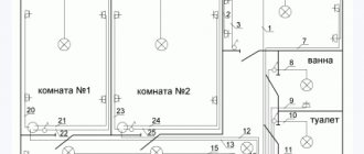
How are escape routes illuminated?
The main goal is to ensure safe, timely exit from the building for residents, workers, and visitors. The evacuation route begins directly in the premises of residence, work and use of services. Therefore, an evacuation lamp and a light sign with a corresponding pictogram should be located above the exit from the room.
Next, emergency lighting equipment is located along the entire evacuation route to its end point - the exit from the building to the outside. They are divided into lamps themselves and light signs with infographics.
Additional tasks of lighting evacuation routes - assistance in access to safety zones; ensuring the ability to combat fire, smoke and other hazards; indication of places of assistance, fire extinguishing equipment and other emergency equipment, location of personal protective equipment and warning points.
Lighting of high-risk areas
The purpose of lighting high-risk areas is to protect the life and health of people from:
- Technological hazards - machines with moving working parts, open tanks with acids and alkalis, live equipment, high-pressure vessels, operating furnaces, etc.
- Hazards associated with heights and transport - unguarded areas with potential for falls, escalators, areas of automatic and human-controlled loading and unloading mechanisms.
Lighting of high-risk areas can be either an independent evacuation subsystem or part of backup lighting (if maintenance and work on the described equipment is expected to continue after an alarm is triggered and/or the main power supply is turned off).
Anti-panic lighting
Equipped in indoor and outdoor areas where an area of at least 60 m2 and/or potential crowds of people may create difficulties with orientation and finding escape routes. The goal is to prevent panic in emergency situations and ensure visibility of directional signs from any point in the zone.
Maintaining good lighting, certainty and unambiguous interpretation of infographics work against confusion. In such conditions, an organized movement to the emergency exit begins immediately after the alarm is announced, which subordinates everyone to a common action, eliminating panic.
Backup lighting
This is the only type of emergency lighting whose main task is not related to the evacuation of people. A number of important technical and humanitarian processes cannot be stopped without serious consequences - death, injury, development of new man-made accidents, etc. Therefore, continuous cycle enterprises, hospitals, train stations, airports, military facilities, security services - they are all equipped with backup lighting systems.
These systems involve providing light with parameters at the level of the main worker. Depending on the task (regular decommissioning of equipment or indefinite continuation of operation), backup lighting is calculated for a period of up to 8 hours or more. As long as necessary - that is, until the main energy supply is restored.
It is not economically feasible to use special separate lamps for backup systems. Therefore, standard lighting equipment, in the event of a failure or disconnection of the main power supply system, automatically switches to a source of centralized emergency power supply.
The presence of backup lighting does not eliminate the need to equip an evacuation system at the site with all the necessary light indicators.
Commissioning and power supply
The CAO is put into effect:
- Automatically - in case of failure/switching off of the main lighting or power supply of the facility as a whole.
- Automatically or from the control panel - when a fire or any other emergency alarm is triggered.
The energy sources of the entire IAS or its individual elements must be independent of the main power supply system of the facility. There are two power supply schemes for emergency and evacuation lighting lamps - centralized (from a central battery pack or backup generator) and autonomous (batteries are included with the lamps).
Emergency lighting power supply circuits
Emergency lighting can be implemented using autonomous lamps, or using a centralized backup power system. Autonomous devices are equipped with their own batteries.
A centralized system is based on a generator, a battery pack with an inverter, or a combination of these 3 devices. The battery pack of an autonomous lamp is called BAP (emergency power supply unit) and contains in its circuit:
- A Ni–Mh or Ni–Cd battery with a capacity that provides 1 or 3 hours of operation.
- Battery charging board with rectifier.
- Inverter (DC to AC converter).
- Grid monitoring circuit (switches on battery power through the inverter if the mains voltage drops below a set limit).
- Indication device (for visual control).
Rice. 2. Power supply circuits with permanent and only emergency switching
Types of lamps
Based on the type of power supply, luminaires are divided into those equipped with an emergency power supply unit (EPU) and without it (GOST 1EC 60598-2-22-2012 clause 22.3.8).
Lamps without BAP are ordinary, familiar to everyone, lighting devices (LDs), which receive backup power from an electrical energy generator and/or battery installation.
Emergency battery emergency lighting lamps with built-in BAP according to operating mode :
- continuous (permanent) action (GOST 1ES 60598-2-22-2012 clause 22.3.5). They continuously receive power from one of 2 sources: the main emergency power supply system or the UPS directly. When the main system is turned off, the lamp is automatically connected to the emergency power supply.
The advantage of this mode of operation is the ease of installation of the circuit and selection of the OP; they do not require special connection skills and can be used at any site.
Constant-on emergency lamps are implemented using conventional artificial lighting fixtures, most often LED emergency lamps, and do not require additional design and installation work. To recognize them, a marking is applied to the OP body - the red letter “A”.
The downside is the high cost.
An example of a continuous (permanent) emergency lamp
DPA-2101
- Emergency (periodic) switching on (GOST 1EC 60598-2-22-2012 clause 22.3.6). A data cable is laid from the distribution board to the OP group, through which a signal is transmitted in the absence of voltage in the main network. The lighting device automatically connects to the UPS and lights up.
The advantage of this mode is its low cost, relative to OP with BAP. Possibility of using inexpensive, low-resource (their operating time is from 1 to 3 hours) components.
Example of an intermittent emergency luminaire KL-60
- Combined (GOST 1ES 60598-2-22-2012 clause 22.3.7). Structurally, they are made of 2 or more lamps, each of which is configured for a specific mode (continuous or emergency).
The operating principle of such a lamp is similar to the power supply circuit of an SAO with two independent light sources. For example, in normal mode: when powered from the main network, lamp No. 1 is on, lamp No. 2 is off. In emergency mode: the voltage in the main network disappears and lamps No. 1, 2 automatically switch to the BAP, while lamp No. 1 continues to light, and lamp No. 2 lights up.
Example of a combined emergency luminaire ONTEC S M1
The design of autonomous emergency lighting lamps directly depends on their functional purpose (operating mode):
- Lamps with surface-mounted shades, linear, modular and raster, are used in backup (evacuation) lamps of continuous (permanent) operation.
Raster lamp
- Spot lamps and lampshades are installed in evacuation lamps of continuous (permanent) or periodic (emergency) operation.
Spotlight
- Rectangular or disc-shaped lampshades with a pictogram printed inside are used in continuous and periodic light indicators.
Example of light indicator (exit)
According to the rules (SP 52.13330.2016 clause 7.6.2), the following light sources can be used to implement self-regulatory systems:
- LED lamp. High luminous efficiency, which allows the use of batteries in BAPs of smaller capacity. The use of an emergency LED lamp is more profitable than incandescent lamps.
- Fluorescent Lamp. Application conditions: the value of the supply voltage (in any mode) is more than 90% of its nominal value, and the air temperature at the installation site is more than 5°C. Most often they are used for backup lighting of objects where the main lighting is provided using gas-discharge lamps.
- High pressure discharge lamp. Application conditions: minimum time to restart the lamp (lights up instantly) regardless of the state (cold or hot). Those. even after it is turned off, it does not require time to cool down before turning on again.
- Incandescent lamp – if the use of other light sources is prohibited.
What kind of device is this
The emergency power supply unit includes two main electrical elements - a battery, a ballast (ballast) and the electronic unit itself. The latter includes:
- battery DC voltage to AC converter;
- pulse type charging device;
- protection against the so-called deep discharge of the battery (when it stops accumulating energy);
- BAP status indicator.
In some cases added:
- additional auto-testing system, which itself checks for faults;
- Possibility to test at the touch of a button.
The emergency power supply for different LED lamps is connected according to different electrical circuits. The difference is determined by the ballast model. The diagram can be found in the instructions for the device.
Which cable to use
The main conditions when choosing a supply cable line (from the distribution board to the lamp) (Federal Law No. 123, Article 82, Part 2):
- fire resistance. The cables are made of special fire-resistant materials that are marked FRLS.
- Preservation of the operational capacity of the self-propelled gun (minimum 1 hour).
Fire-resistant cable line (FRLS)
Lamp placement locations
Lighting devices are installed along the entire length of the evacuation route (SP 52.13330.2016 clause 7.6.3):
- in places of emergency exit/entry from the building;
Sign above the exit/entrance
- corridors and passages along the evacuation route;
Placement of illuminated signs in corridors
- flights of stairs. The light is adjusted so that each step is illuminated by a direct stream of light;
Placement of illuminated signs on stairs
- in places where the level changes (difference point) of the floor covering;
Placing signs where floor levels change
- in places where the evacuation route changes (intersections, turns);
Placing signs at route changes
- long wide rooms. Along a straight axis running from one exit to another, there is a “light corridor” 2 m wide (1 m in each direction from the axis);
Placing signs in wide areas
- above the established evacuation scheme (plan) and medical aid point;
Evacuation plan illumination
- location of fire extinguishing equipment (fire hydrant, sand containers, shovels, buckets) and emergency communications.
Fire shield lighting
Lighting of high-risk areas
Lighting of high-risk areas is important to preserve the life and health of personnel involved in continuous production processes. Such places include:
- premises with traumatic equipment installed in it;
- elevators, boiler rooms;
- building halls;
- along the entire evacuation route;
- Technical buildings;
- rooms where emergency system control panels are installed.
The minimum illumination value is 15 Lux, the maximum is 150 Lux. Those. the ratio of illumination unevenness at the minimum and maximum points is 1 to 10 (SP 52.13330.2016 clause 7.6.7, table 7.28).
Checking the emergency light
The performance of lamps and signs equipped with BAP must be checked by the chief power engineer of the enterprise at least once every 14 days.
For this purpose, the design of emergency OPs is equipped with a special self-release button or connector (Federal Law No. 123, Article 82, Part 9; GOST 1ES 60598-2-22-2012, Section 22.20). The self-release button prevents the human factor and the discharge of the self-propelled gun (the person turned on the OP, got distracted and forgot to turn it off).
Emergency lamp with self-release button
The check is carried out in two ways:
- alternate individual inspection of each OP (in small rooms and places with an accessible approach):
- the button installed on the lamp is pressed and its working condition is visually checked;
- a testing device is connected to the connector and the performance of the lamp is also assessed.
This check is performed by one person.
- Group inspection of OP (in large premises: warehouses, trading floors, places with difficult access). A group of lamps (maximum number of 35 pieces) is connected to a device that supplies a 12 V signal to the control data cable.
Device for group testing of self-propelled guns (TELEKONTROL)
The check is carried out by 2 people: the 1st presses and holds the button, the 2nd carries out a visual check.
The results of the inspection are recorded in the emergency lighting equipment logbook.
Lamps with batteries
In lamps with batteries, periodic checking requires not only the lamps, but also the battery itself.
Regardless of the type of battery (lithium - cadmium / ion), its capacity must be measured every six months. The results of the inspection are documented in a document. Batteries with performance below standard values are not allowed for use and must be replaced.
Rechargeable batteries (AB)
The battery life is 3-4 years. Accordingly, in order to prevent emergency situations, it is necessary to replace it after its service life has expired.
It is recommended to recycle obsolete batteries or, as a last resort, throw them in a trash container.
Popular models
- Model: SKAT LT-2330 LED Li-Ion
SKAT LT-2330 LED Li-Ion
Technical characteristics of SKAT LT-2330 LED Li-Ion:
Technical characteristics of SKAT LT-2330 LED Li-Ion
- Model: SKAT LT-301200 LED Li-ion
SKAT LT-301200 LED Li-ion
Technical characteristics of SKAT LT-301200 LED Li-ion:
Technical characteristics of SKAT LT-301200 LED Li-ion
- Model: RAPAN LT-30 Li-ion
RAPAN LT-30 Li-ion
Technical characteristics of RAPAN LT-30 Li-ion:
Technical characteristics of RAPAN LT-30 Li-ion
The models considered are presented on the market (https://bast.ru), and each lamp is made in a modification from 30 to 90 LED elements.
Conclusion
The above-described emergency lighting systems are capable of providing in practice any case of energy backup. It should also be mentioned that it is necessary to take care not only of emergency lighting, but also of the supply of electricity to equipment, the sudden cessation of operation of which can lead to unpleasant consequences.
To make the correct choice, as well as create any scheme, it is necessary to conduct a primary analysis, during which you find out the required network power, the conditions for using the lamps, and the time for reservation. It is also very important to consider the methods of installing power lines - overhead or cable.
The good thing about a cable connection is that in this case the risks of a break are practically eliminated, while air connections are susceptible to such troubles. Very often, overhead wires break while trees are being cut down, or they are caught by oversized vehicles. The disadvantage of cable switching is the difficulty of repair.
Fire certificate
One of the functional features of some models of emergency lamps is a fire alarm.
When the fire alarm system is activated, the lamp receives a warning signal using a special connector and lights up. This notifies you of a fire.
A mandatory condition for the operation of fire emergency lighting lamps is the presence of a certificate of conformity (fire certificate) (Federal Law of the Russian Federation No. 123). If it is absent, the lamp has no warning function.
Example of a fire certificate
One of the tasks of emergency lamps is protection from the effects of electric current (TR TS 004/2011 art. 4).
Requirements for pointers
Evacuation signs:
Table of characteristics of evacuation signs (part 1)
Table of characteristics of evacuation signs (part 2)
Table of characteristics of evacuation signs (part 3)
Fire signs:
Table of characteristics of fire signs (part 1)
Table of characteristics of fire signs (part 2)
Table of characteristics of fire signs (part 3)
Illumination of escape routes
When choosing a pointer, it is important to pay attention to its color. It should not be too dark and not transmit light, and should also have a pronounced contrast (no less than 1:15 and no more than 1:5) to the index figure, for example green/red to white (SP 52.13330.2016 clause 7.6. 10).
Information signs “direction of movement” are installed as you move and are green (GOST 12.4.026-2015 clause 5.1.6), “first aid kit, fire hydrant, communications” signs are red (GOST 12.4.026-2015 clause 5.1.6). 5.1.2).
On each sign, a white border (frame) with a width of no more than 0.025 of the height of the sign is applied along its perimeter (GOST 12.4.026-2015 clause 6.3.3.5).
The aspect ratio of the signs (including the rope) is 2:1 for a rectangular shape, 1:1 for a square (GOST 12.4.026-2015 clause 6.3.3.5).
Signs installed along evacuation routes may have their own lighting or a separately installed lamp, the luminous flux of which is directed towards the pictogram.
The brightness of green lighting in rooms is (SP 52.13330.2016 clause 7.6.10):
- if there is a smoke removal system - 2 cd/sq.m.;
- in the absence of a smoke removal system - no less than 2 and no more than 10 cd/sq.m.
The light should spread as evenly as possible (at least 1:5) over the surface of the sign (SP 52.13330.2016 clause 7.6.10).
Evacuation signs
Signs are installed at a height (SP 52.13330.2016 Appendix B), the minimum value of which is equal to the ratio of the maximum visible distance L to the coefficient k equal to 200 (lighting from the outside) or 100 (lighting from the inside)
Hmin = L/k
Dependence of the height of the safety sign on the distance
Noise immunity
The voltage in the network has a sinusoidal shape due to alternating current. At the maximum and minimum points of the sinusoid, electrons are released (emission) corresponding in power. This affects the evenness and stability of the light flux.
To equalize the voltage, the design of the emergency lamp is equipped with a filter. A stable luminous flux in emergency situations is important in the work of military and medical, school and preschool institutions, as well as in heavy industrial facilities.
This lamp can be used as an emergency lamp, because... it meets electrical safety standards and electromagnetic compatibility conditions (GOST R 51514-2013).
Electromagnetic Compatibility Certificate
Using one lighting device (any type of light bulb) for normal and emergency modes
This type of emergency lighting system is built on the principle of continuous power supply to the lighting elements. Regardless of whether an emergency occurs, the lighting equipment operates on alternating current. The emergency lighting circuitry is capable of stabilizing alternating current in the event of unexpected failures in the power grid.
The emergency lighting control circuit, which uses one lighting device for all operating modes and lighting elements of any type, consists of the following components:
Emergency lighting, one light source for normal and emergency mode
This system is very similar to the previous one, but still differs from it in the presence of an inverter. This element converts battery charge into alternating current. In the event of an emergency, the lighting element is powered from the network through an inverter and rectifier. Using this system, you can achieve an imperceptible transition from normal operation to emergency operation.
Useful tips Connection diagrams Principles of operation of devices Main concepts Meters from Energomer Precautions Incandescent lamps Video instructions for the master Testing with a multimeter
Flammability test
Emergency OP corresponds to the following parameters:
- housing resistance to high temperatures up to 850 0C (GOST 1ES 60598-2-22-2012 clause 22.15);
- the housing prevents further spread of fire, i.e. does not burn (GOST 1ES 60598-1-2072 clause 13.3).
Fire resistance testing is carried out by the manufacturer (GOST 1EC 60598-1-2072 clause 13.3.1):
- parchment is placed under the body of the test sample;
- an open needle flame is applied to the point of the body most susceptible to heating for 10 seconds;
- the test flame is removed;
- if the housing is on fire, it should extinguish within 30 seconds;
- drops from the melting of the body falling on the parchment should not cause it to ignite.
Connection diagram options
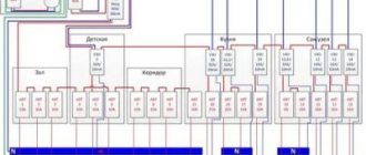
Emergency lighting connection:
- Power circuit with two different lighting sources
Power circuit with two different lighting sources
On the diagram:
L1 – work lighting lamp;
L2 – emergency lighting lamp;
K1,2 – relay contacts, respectively, working and emergency lighting. The relay coils of these contacts belong to secondary switching devices and are not indicated in this diagram, because it is of a “principled nature”;
Pr1,2 – fuse;
AKB – rechargeable battery;
B – rectifier, converts alternating current from the network into direct current for constant charging of the battery;
And - inverter, converts the direct current of the battery into alternating current to power the emergency lamp.
Normal operation:
- there is voltage in the main network;
- relay K1 receives a signal indicating the presence of voltage in the network, its contacts are closed;
- The power supply circuit for lamp L1 is closed;
- lamp L1 is on.
Operation of the circuit in an emergency:
- there is no voltage in the main network;
- relay contacts K1 open;
- a signal is sent to relay K2, its contacts close;
- The power supply circuit for lamp L2 is assembled;
- voltage is supplied from the battery through the inverter to lamp L2;
- lamp L2 lights up.
This scheme allows you to use any types of lamps as the main lighting, because they do not carry the functions of the CAO.
The disadvantage is the cost of installing autonomous emergency lighting.
- Power circuit with one light source
Power circuit with one light source (with inverter)
The symbolic and graphic designation of the circuit corresponds to a power supply circuit with various lighting sources. Also, the relay contact coils K1.1, K1.2, K2.1, K2.2 belong to secondary switching devices and are not indicated on this diagram, because it is of a “principled nature.”
Normal operation:
- there is constant voltage in the main network;
- a signal is sent to relay K1 indicating the presence of voltage in the network, its contacts K1.1 and K1.2 are closed;
- The power supply circuit for lamp L is closed, the lamp is on.
Operation of the circuit in an emergency:
- there is no voltage in the main network;
- contacts K1.1 and K1.2 of relay K1 open;
- a signal is sent to relay K2, its contacts K2.1 and K2.2 close;
- The power supply circuit for lamp L is assembled;
- voltage is supplied from the battery through the inverter to lamp L, the lamp lights up.
The advantage of the scheme is the cost-effectiveness of self-propelled artillery equipment due to its implementation on the elements of the main line, which allows maintaining the brightness level of the light flux. And also low consumption of electrical energy due to the use of an inverter.
In the case of a circuit without an inverter, electricity consumption increases significantly.
Power circuit with one light source (without inverter)
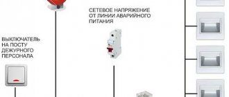
- Connection diagram for emergency lights via a switch
Connection diagram for emergency lights via a switch
For emergency lighting devices implemented on the basis of main lighting fixtures, the question arises of connecting a switch, because in the “off” position, the power supply circuit for the working lighting is broken.
To make it possible to automatically switch on the operation of the automated control system, an additional cable line is provided from the control panel to the control room data.
If there is no voltage in the control panel (and not at the switch!), a signal is sent to a special relay, which, by closing its contacts, supplies power to the emergency lighting.
For reliable power supply to such circuits, it is recommended to connect the power supply of the emergency lighting system to a separate emergency lighting panel (ELS).
Control circuit for self-propelled guns with intermittent lamps
Operating principle of the circuit:
- The BS-RKF phase control relay controls the voltage level in the main switchboard of the ShchO.
- If there is no voltage (or a surge) in the SC, the BS-RKF relay sends a signal to relay K1.
- Contacts K1.1, K1.2 of relay K1 close and the group of intermittent lamps AO BS lights up.
Thus, the EAS power supply does not depend on the working light switch. In this case, you can use LED emergency lights.
Battery-powered lamps
The operation of the devices is quite simple. In a normal state, when there is voltage at the input, the electronic circuit charges the battery and monitors its condition. At the moment of a power outage, the lamp starts from the battery and the emergency lighting turns on.
The second scheme for emergency lighting at home is more complex; it contains a charge control chain, batteries:
The LM 317 integrated stabilizer provides the circuit with a constant voltage, transistor T1 is in the feedback chain, controls the amount of charge on the battery and regulates the stabilizer by adding or decreasing the voltage. On the T2 key, there is an organized circuit for starting emergency lighting. If there is a positive voltage at the base, the LEDs do not work.
What kind of lighting do you prefer?
Built-in Chandelier
The described devices have one nuance: they only monitor the presence of voltage at the input. If there is a power outage during daylight hours, the emergency lights will honestly serve their purpose. Those. will work until the battery is discharged or electricity is supplied. Therefore, it is better to make backup lighting according to the following scheme:
This option contains a photo relay, which will not allow you to turn on emergency lighting in the house during daylight hours. On transistor T1, a light control unit with photoresistor LDR1 is organized. As you can see, they are not complicated, the elements are accessible and common.
As a ready-made solution, you can use UPS computer uninterruptible power supplies. In this case, the installation of the emergency lighting group should be carried out using a separate cable from the power group, but the luminaires should be powered in transit, via UPS. This device can use conventional and 220-volt compact fluorescent lamps.
By the way, we talked about how to choose an uninterruptible power supply in the corresponding article. Check out the tips if you want to install emergency lighting in your home using a UPS.
This circuit contains a charger, a low voltage relay, a diode, and a 12/220 converter. You don’t have to install it, but use 12 Volt LED modules instead.
How to create emergency lighting on site
To implement emergency lighting for industrial premises, preliminary preparation of design calculations with the choice of lighting equipment, type of emergency power supply and phased installation work is necessary. All stages must be carried out in accordance with the rules and approved by the relevant authorities.
Composition of the CAO project
Before the start of design work, initial data on the specified object is collected:
- building drawing;
- a plan of premises with hazardous production facilities and evacuation routes marked on it;
- electrical and schematic diagram of the building's power supply and main lighting;
- features of the functioning of the building premises;
- description of the facility's production activities.
The emergency lighting system design consists of:
- explanatory note - a general description of the work and composition of the CAO;
- calculation of equipment selection and installation;
- plans (drawings) showing the general layout of the building with:
- installation location of lamps;
- route for laying supply (power) lines;
- data cable route;
- power supply/backup power supply;
- control system;
- monitoring system.
- Specification for each system;
- address list (when designing a lighting control system with digital addressing);
- maintenance plan;
- manual.
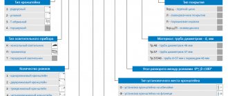
Choice of lighting equipment
To carry out lighting engineering calculations, the designer analyzes the source materials and draws up a preliminary CAO plan. This calculation allows you to select the following technical characteristics:
- lamp design;
- Light source;
- light flow;
- power consumption.
The choice of the SAO power supply system and its parameters is influenced by:
- the area of the object and, as a consequence, the total number of OPs and their total power;
- the operational mode of the facility affects the availability of backup lighting and the operating time of the self-propelled gun;
- the presence of open areas and exhaust systems (anti-panic lighting);
- classification of potential fire and places with increased fire danger;
- existing self-service system (connectivity, taking into account its expansion);
- architectural solutions (OP design).
Upon completion of the selection of CAO equipment, a verification calculation of lighting is carried out.
Control and monitoring system
Controlling and monitoring the condition of self-propelled waste at large facilities manually is difficult and time-consuming, so constant monitoring is carried out using an automated system: a control unit or a computer with special software, a data cable (for transmitting test and control pulses), and lighting devices. Control via wireless interface is possible.
The following equipment is subject to monitoring:
- battery and its charge level;
- emergency lighting switch and its working condition;
- operability of emergency OPs;
- good condition of cable lines.
Installation with further operation
Installation of self-propelled guns at small facilities can be carried out with the help of a trained electrician, while at large facilities it is worth contacting specialized organizations.
Trained personnel specialized in self-propelled guns will carry out complete installation of the system, taking into account the design and standardized rules, as well as its maintenance during operation.
Having trouble choosing emergency lights?
We will prepare a full calculation of the cost, necessary equipment and 3D visualization for emergency lighting of your facility. It’s FREE - even before purchasing and concluding a contract, you can find out: “How many and what kind of lamps are suitable?”, “How much will it cost?”, “What will it look like?”
and even “How long will the counter wind up?” More about this
In what areas is the use of CAO mandatory?
The system should be installed wherever artificial lighting is provided, with rare exceptions. We are talking about those buildings and areas where there cannot be a critical concentration of people on evacuation routes. These are, first of all, private cottages and residential buildings of no more than 5 floors with staircase landings of a simple layout and a small number of apartments per site.
General recommendations
If there is at least one turn from the exit from the apartment to the elevator or stairs, evacuation lighting is necessary. And, of course, they must be equipped with:
- High-rise residential buildings.
- All public, commercial and industrial facilities.
- Indoor and outdoor areas of gas stations, parking lots and transport tunnels.
- Experts in the field of man-made disasters believe that special attention should be paid to evacuation lighting when designing utility lines for:
- Objects characterized by high crowding of visitors (organization of mass entertainment events).
- Establishments with retail trade of alcohol on tap (bars, restaurants, nightclubs).
- Objects of old construction with high attendance (museums, galleries, clubs, etc. establishments in buildings related to cultural heritage).
Backup lighting in case of power supply failures not related to the need to evacuate people is necessary:
- In production with a continuous technological cycle.
- In medical institutions.
- At airports and train stations
- At any other facilities where even a short-term stoppage of activities can lead to casualties, accidents and/or significant losses.
Emergency lighting in cafes, bars, restaurants
Emergency lighting is installed in the foyer and areas with seating/bar counters. If the area of these zones is > 60 m2, and the expected number of visitors reaches 30 people or more, the premises are also equipped with anti-panic lighting equipment.
In the simplest case (small coffee shops, snack bars with 2 to 4 tables with a basic layout), it is enough to ensure that an internally illuminated light sign with a corresponding pictogram is installed above the exit. But this is what concerns the main hall. In addition, regardless of the scale of the establishment, evacuation lighting is provided in auxiliary (dressing rooms, toilets, corridors) and production areas (kitchens, storerooms, administrative premises).
Large establishments and facilities with complex layouts require more comprehensive engineering solutions.
Important nuances when developing a self-regulatory system for cafes, bars and restaurants are:
- Taking into account the increased fire hazard of display cases, shelving and other places where alcoholic beverages are stored - the speed of flame spread, the high probability of smoke, the location of fire extinguishing equipment and fire detectors are taken into account.
- Lighting of high-risk areas in kitchens - anything associated with high temperatures and high-voltage equipment.
Emergency lighting in shops and retail facilities
All types of retail commercial enterprises are required to be equipped with CAO, regardless of their location and architectural features. In halls S < 60 m2, emergency lighting must be installed. Larger premises are also equipped with anti-panic lighting equipment.
Typical high-risk areas that require appropriate emergency lighting in retail premises include:
- Logistics hubs (area for loading/unloading goods, as well as warehouses with goods of flammability classes G2 and higher).
- Entry and exit areas for transport equipment (at escalators and elevators).
- Electrical switchboards, control points for utilities and equipment running on backup power).
Emergency lighting in medical institutions
The main feature of CAO at healthcare facilities is an extensive list of premises with mandatory backup lighting. Since they must continue to function in any emergency conditions accompanied by a shutdown of the main lighting, backup lighting equipment is installed in:
- Operating units, manipulation rooms and analytical laboratories.
- Intensive care wards.
- Maternity wards.
- Service posts.
- Pharmacy points.
- At the training and waiting points for ambulance teams...
- Dressing rooms, pump rooms, lobbies, heating points.
Other types of emergency lighting - evacuation, anti-panic and high-risk areas in medical institutions - are equipped in accordance with the general requirements of specialized standards.
Industrial and warehouse emergency lighting
Shops, workshops, warehouses, open technological sites and other production premises and areas are objects with mandatory equipment of self-propelled guns. In most workshops it is necessary to install all types of evacuation lighting: escape routes, anti-panic lighting, as well as high-risk areas.
In addition to evacuation systems, backup lighting is installed:
- In production facilities with a continuous technological cycle
- On installations and systems whose sudden shutdown could lead to loss of life (or threat to human health) and serious accidents.
Emergency lighting in offices
IAS for office premises, with one exception, are mandatory and are regulated by the general provisions of GOST R 55842, as well as the subclause of this standard “Emergency lighting of high-rise buildings”. Without emergency lighting equipment, only one type of office can be operated - simple-plan premises with an area of no more than 30 m2, located on the first floors of buildings and having a separate exit to the street (it is also the only one). In this case, the total number of staff and visitors should not exceed 15 people.
In addition to lighting evacuation routes, anti-panic systems are relevant for offices, mandatory for areas of more than 60 m2 and the total number of staff and visitors ≥ 30 people.
Rice. 3. Lighting of key areas of escape routes
Where are emergency lights installed?
Technical standards only stipulate the location of evacuation lighting equipment, since the backup function is performed by the main lighting equipment of working lighting. Emergency/evacuation lamps are installed in:
- Key points along the evacuation route - this includes changes in direction of movement and floor level, staircases, entrances and exits, places with manual call points, fire extinguishing equipment and PPE storage, etc.
- High-risk areas (they should not be included in designated evacuation routes from buildings, but some people may be there at the time the alarm goes off and the emergency lighting turns on) are passenger elevators, escalators, open-air and multi-story parking lots.
- Corridors, foyers, halls, lobbies (registration areas, receptions), toilets (except for toilets in hotel rooms and toilets for one healthy person).
Evacuation infographics and its relationship with emergency lighting
All signs related to the designation of evacuation directions, danger zones, locations of emergency equipment, etc. - can be externally or self-illuminated. Self-illuminated pictograms are classified as illuminated signs. For pictograms, the rule of sufficient visibility applies: MIN sign height is calculated using the formula h = L/200, where L is the maximum viewing distance. For example, from 20 meters, infographics with a height of at least 100 mm should be viewed.
Rice. 4. Location and dimensions of evacuation and other emergency pictograms
Minimum operating time of the self-propelled gun system
In an emergency, lighting should be provided for a period sufficient to allow evacuation or essential work to be carried out. The minimum required duration of operation of the self-propelled gun system in the regulatory tables is called the design duration and is determined in hours. The maximum permissible response time of the system is referred to as “on time” or “response time” and is expressed in seconds.
For most rooms, the design duration is 1 hour or 3 hours. For backup lighting, the parameter can be increased to 8 hours. The response time to 50% of the design illumination should be ≤ 5 s, and to 100% should not exceed 60 s. In high-risk areas, the response time is reduced to 0.5 s to reach 100% illumination.
Standards of illumination and other parameters of emergency lighting
The required levels of illumination, design duration and response time must correspond to the types of objects, types of premises and typical areas.
| Functional parameters of emergency lighting systems at commercial facilities | |||||
| Room type | Type of lighting | Min illumination, lux | Response time, s | Estimated duration, h | Illuminated signs |
| Retail | |||||
| Trading areas > 60 m2 | Anti-panic | 0,5 | 15 | 1 | + |
| Evacuation | 1 | 15 | 1 | + | |
| Sales areas < 60 m2 | Evacuation | 1 | 15 | 1 | + |
| Evacuation routes | Evacuation | 1 | 15 | 1 | + |
| Places in front of exits and other important evacuation areas. route | Evacuation | 5 | 15 | 1 | + |
| Entrances and exits from escalators, pre-lift platforms | High danger zones | 15 | 0,5 | 1 | — |
| Service and emergency aid posts | Evacuation | 5 | 15 | 1 | + |
| Points with equipment powered by emergency power supplies, loading/unloading areas | High danger zones | 10% of the base, but ≥ 15 | 0,5 | 1 | — |
| Passenger elevators | Evacuation | 1 | 15 | 1 | + |
| Cafes, bars, restaurants | |||||
| Halls > 60 m2 with the ability to accommodate more than 30 people | Anti-panic | 0,5 | 15 | 1 | + |
| Evacuation | 1 | 15 | 1 | + | |
| Halls < 60 m2 | Evacuation | 1 | 15 | 1 | + |
| Evacuation marches | Evacuation | 1 | 15 | 1 | + |
| Places in front of exits and other important evacuation areas. route | Evacuation | 5 | 15 | 1 | + |
| Areas with potentially hazardous equipment (ovens, stoves, etc.) | High danger zones | 10% of the base | 0,5 | 0,5 | _ |
| Pass. and cargo. elevators | Evacuation | 1 | 15 | 1 | + |
| Offices in multi-storey buildings | |||||
| Evacuation marches | Evacuation | 1 | 15 | 1 | + |
| Elevators and emergency sites | Evacuation | 5 | 15 | 1 | + |
| Service and emergency aid posts | Evacuation | 5 | 15 | 1 | + |
| Points with power supply powered by emergency power supplies | High danger zones | 10% of the base | 0,5 | 1 | + |
Centralized emergency lighting
Centralized emergency lighting is a modern way to control and manage emergency lighting systems at large sites (shopping centers, industrial enterprises, office buildings).
The system controls a group of OPs (by floors, rooms) or each luminaire; for this, it is given its own “address”.
Centralized CAO scheme
Emergency lamps in such a system are made without BAP, and their testing is carried out using controllers, the control of which is controlled by one remote control.
Advantages of a centralized CAO:
- The frequency of testing is entered into the controller and is carried out automatically. The results are stored in the controller's memory.
- Reliability. Achieved due to the minimum configuration of the emergency lighting lamp.
- Cost-effective compared to free-standing autonomous OPs.
- Service life (12 years) of the central battery installation.
- Coordination in working with the fire warning system.
- One control point (remote control).
- Modernization of the existing system.
Popular CSAO models
Popular CSAO models, their descriptions and technical characteristics are provided by the international group.
TSAO DIALOG-20-AM00-AC00-3-1
Parameters of CSAO DIALOG-20-AM00-AC00-3-1
- Uninterruptible power supply DIALOG 24-4-400-1H
UPS DIALOG 24-4-400-1H
Parameters of UPS DIALOG 24-4-400-1H
- Telemando remote testing and emergency lighting control device
Telemando remote testing and emergency lighting control device
Telemando device parameters (part 1)
Telemando device parameters (part 2)
- Related Posts
- What are gas discharge lamps
- Antibacterial (bactericidal) lamp: beneficial and negative properties
- What are fluorescent fluorescent lamps and what are they?
Technologies and equipment for emergency lighting
Emergency lighting technologies provide two options for the operation of lighting devices: switched on only in case of emergency and constantly switched on. The first of them operate from a signal coming from an additional wire that is connected to the distribution panel. It transmits the potential to the logic block, which ensures that the relay is held in the main lighting position, due to which the emergency lighting is in the off state. When the voltage in the switchgear fails, the potential in the additional wire disappears and the relay switches the lighting to emergency.
The second technology offers LED models powered by a battery. Due to their low power, they do not burn out and boast a long service life.