Why is the mode called “dialing”?
It was possible to check the integrity of the circuit before using the resistance measurement mode - an ohmmeter. The main difference between dialing is that during measurements, if there is an electrical connection between the tested areas, then, in addition to the readings on the screen, a sound signal is heard - a buzzer, which is where the term dialing or ringing came from.
This sound signal significantly speeds up the verification process, you don’t have to be distracted, look at the screen, and it’s not always convenient, and when you hear the buzzer (or not), you already know the result. This is especially useful for mass measurements, for example, when searching for one specific wire in a bundle.
Multimeter for testing wires
What do you need to know about this device? Firstly, it is worth noting the price variety and availability. Even inexpensive multimeters can flawlessly cope with many tasks, including testing wires.
Let's take a closer look at a typical budget option. Let's get acquainted with the design, layout and determine its functionality.
As you can see, a typical device has a digital display, controls and sockets for connecting probes. Let's decipher the main modes of the multimeter:
- OFF – the device is turned off (some devices have a special button for this).
- ACV (may be designated V~) – measurement of alternating voltage.
- DCV (can be designated V...) – DC voltage measurement.
- ACA (may be designated A~) – measurement of alternating current.
- DCA (may be designated A...) – direct current measurement.
- Ω - resistance measurement.
- hFE – measurement of transistor parameters.
- ->Ι- – conductivity check (circuit continuity).
The sockets for connecting probes are marked as follows:
- COM(-) – common socket for connecting the black wire.
- VΩmA(+) – socket for connecting the red wire.
- 10A ... MAX – socket for connecting the red wire when measuring direct current, the maximum value of which does not exceed 10 Amperes.
Within the framework of the issue under consideration, only two modes of the multimeter will be considered:
The presence of sound, which is not mandatory, complements the dialing mode and simplifies the verification process. You do not need to constantly be distracted and look at the device display. The presence or absence of a buzzer signal will give a clear indication of the integrity of the conductor being measured.
Expert opinion
It-Technology, Electrical power and electronics specialist
Ask questions to the “Specialist for modernization of energy generation systems”
How to test wires with a multimeter: instructions, photos, videos How to test wires with a multimeter has been discussed, but this mode can also make other measurements, for example, you can determine. Ask, I'm in touch!
Continuity indication on a multimeter
In one of the recent articles - “How to use a multimeter”, I already talked about the main operating modes of a standard tester, measurement limits and testing methods, in particular about the dialing function, which has the following designation:
As you can see, the marking accurately conveys the main meaning of this mode, because it consists of two elements - a diode icon, which symbolizes the test, and a buzzer, indicating a sound signal.
Operating principle of dialing
For a better understanding of how exactly the multimeter finds out whether there is an open circuit or not, I will, in general terms, describe the principle of operation of this mode.
Everything here is extremely simple, the operating principle of dialing is based on the well-known Ohm’s law, the main rule of electrical engineering:
I = U / R , where I – current, U – network voltage, R – resistance
Each multimeter has a power source - a battery or an accumulator, with the help of which a voltage is created on the section of the network being tested - a current is supplied and, knowing its characteristics, the result is calculated.
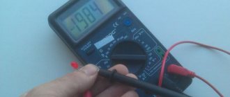
What does the multimeter show when making a call?
The multimeter, when tested, shows the calculated voltage drop in millivolts in this circuit.
The current created by the tester in the area being tested, about 1 milliampere, was not chosen by chance, since the voltage drop in millivolts in this case corresponds to the resistance in Ohms.
In other words, when testing electrical circuits or electrical materials, we are shown the magnitude of the voltage drop, which is equal to the resistance of this section in Ohms.
Multimeter DT-830C does not display voltage correctly
- Author
- Message
Multimeter DT-830C does not display voltage correctly
Re: Simple human weaknesses
Re: Simple human weaknesses
Re: DT-830C multimeter displays incorrect voltage
It is useful to start any repair by measuring the voltages in the sensitive components of the circuit. Judging by the specification for the ICL7106 “drop” on which all these multimeters are built, here this is the reference voltage VREF HI, which should be 100 mV at the REF HI pin.
Testing the wire with a multimeter
1. Install the probes into the multimeter connectors:
— Red probe into the V Ω mA
— Black probe into COM
2. We switch the control wheel to dialing mode, which is marked accordingly (diode and buzzer icon). One should appear on the screen.
3. We check the correct operation of the multimeter by connecting the contacts of the probes by shorting them.
If the device is working correctly, you will hear a buzzer sound and a value close to zero will appear on the screen.
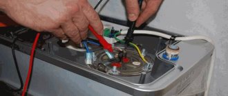
4. We call the wire. By applying the multimeter probes to its wires on both sides, as shown in the image below. If the conductor is intact, then you will immediately hear a buzzer sound, and the readings on the screen will be close to “0”, for example 0.001.
If the wire core is damaged and one of its ends does not have an electrical connection with the other, then the multimeter readings will not change, “1” will be displayed and there will be no sound signal.
As you can see, everything is quite simple, and if you have a multimeter at hand, you can try to ring something yourself. Just let me remind you once again - do not call under voltage, even under low voltage.
One of the clear, often found in everyday life, examples of checking wiring with a multimeter is described in our next article - HOW TO RING AN OUTLET. This is a detailed, step-by-step instruction for diagnosing a non-working outlet; be sure to study it to understand how to connect the electrical wiring.
How to use the DT 830b multimeter correctly?
- Red wire “V Ω mA”, black with “COM” (for measurements between 220 mA and 10 A, connect the red wire to the 10 A compartment).
- Set the switch to the selected DCA position.
- Open the circuit to be measured and connect the wires in series with the load inside.
- Read the current reading on the display.
We install the leads into the required sockets of the device and connect the probes to each other. As a result of these manipulations, a zero reading or as close as possible to it should appear on the multimeter screen. It is this simple zero resistance test that checks the serviceability of the multimeter.
How to test wiring with a multimeter in an apartment (house)
Modern appliances come with a variety of features, replacing the few appliances that were used in earlier times. To understand how to test wires with a multimeter , you need to know basic information about the device. The device includes:
Expert opinion
It-Technology, Electrical power and electronics specialist
Ask questions to the “Specialist for modernization of energy generation systems”
How to test wires with a multimeter: two ways to find a broken cable Back in Soviet times, when only wired telephones were used, cables consisting of dozens of wires were used. Ask, I'm in touch!
What to do if the multimeter does not have a dialing mode
Some budget electronic testers do not have a separate dialing mode with a sound alert, but they can also check the integrity of the circuit , but this is not so convenient.
For example, the fairly popular dt 830b does not have a buzzer, but there is a diode test mode, you can use it by observing the change in readings on the screen. The probes are connected in the same way as described above into the COM and V Ω mA .
If the readings on the screen during measurements differ from one, then there is an electrical connection in the area being tested. You can check the functionality of this method by connecting the probes; if everything is in order, then zeros should appear on the screen.
In multimeter models, where there are no additional functions at all, in particular in analog instruments, you can ring by switching the regulator to the resistance measurement mode - ohmmeter.
In this case, it is necessary to select the lowest available threshold - for example, 50 Ohms or 200 Ohms. Then measure according to the usual scheme described above and watch the changes in the readings on the screen - if there are changes, the circuit is intact. For home, everyday conditions, this is quite enough to find which wire is broken, determine the burnt track on the board, and much more.
That's all for me; in my opinion, this information is quite enough for anyone to learn how to dial with a multimeter, even without ever doing it before. If you still have questions or have healthy criticism or additions, be sure to write in the comments to the article, in addition, subscribe to our VKONTAKTE group - stay tuned for new materials.
In the following articles we will talk about other useful functions and ways to use a digital multimeter in everyday life, determine the phase and zero in an outlet, measure the voltage in the network and much more, stay tuned .
It is impossible to imagine a repairman's workbench without a convenient, inexpensive digital multimeter. This article discusses the design of digital multimeters of the 830 series, the most common faults and methods for eliminating them.
Currently, a huge variety of digital measuring instruments of varying degrees of complexity, reliability and quality are produced. The basis of all modern digital multimeters is an integrated analog-to-digital voltage converter (ADC). One of the first such ADCs suitable for building inexpensive portable measuring instruments was a converter based on the ICL71O6 chip, produced by MAXIM. As a result, several successful low-cost models of digital multimeters of the 830 series were developed, such as M830B, M830, M832, M838. Instead of the letter M there may be DT. Currently, this series of devices is the most widespread and most repeated in the world. Its basic capabilities: measuring direct and alternating voltages up to 1000 V (input resistance 1 MOhm), measuring direct currents up to 10 A, measuring resistances up to 2 MOhm, testing diodes and transistors. In addition, some models have a mode for audibly testing connections, measuring temperature with and without a thermocouple, and generating a meander with a frequency of 50. 60 Hz or 1 kHz. The main manufacturer of multimeters in this series is Precision Mastech Enterprises (Hong Kong).
How to properly use a multimeter for dummies. | Hereditary master
- V;
- A;
- Ω;
- ºС;
- diode and beep icon;
- V – voltage sign, next to which there are letters
- DC – constant or AC – variable. Instead of letters, the symbol for direct and alternating voltage can be used.
- A – current sign. Multimeters are designed for DC or pulsating current only.
- Ω is the sign of resistance.
- ºС is a sign of temperature.
- The diode and beep allows you to check diodes and ring wires.
- hFE – in this mode, transistors are checked.
Scheme and operation of the device
Rice. 1. Block diagram of ADC 7106
The basis of the multimeter is the ADC IC1 type 7106 (the closest domestic analogue is the 572PV5 microcircuit). Its block diagram is shown in Fig. 1, and the pinout for execution in the DIP-40 housing is shown in Fig. 2. The 7106 core may have different prefixes depending on the manufacturer: ICL7106, TC7106, etc. Recently, DIE chips have been increasingly used, the crystal of which is soldered directly onto the printed circuit board.
Rice. 2. Pinout of ADC 7106 in DIP-40 package
Let's consider the circuit of the M832 multimeter from Mastech (Fig. 3). Pin 1 of IC1 is supplied with a positive 9 V battery supply voltage, and pin 26 is supplied with a negative voltage. Inside the ADC there is a source of stabilized voltage of 3 V, its input is connected to pin 1 of IC1, and the output is connected to pin 32. Pin 32 is connected to the common pin of the multimeter and is galvanically connected to the COM input of the device. The voltage difference between pins 1 and 32 is approximately 3 V in a wide range of supply voltages - from nominal to 6.5 V. This stabilized voltage is supplied to the adjustable divider R11, VR1, R13, and its output is fed to the input of microcircuit 36 (in measurement mode currents and voltages). The divider sets the potential U eg at pin 36, equal to 100 mV. Resistors R12, R25 and R26 perform protective functions. Transistor Q102 and resistors R109, R110nR111 are responsible for indicating low battery power. Capacitors C7, C8 and resistors R19, R20 are responsible for displaying the decimal points of the display.
Rice. 3. Schematic diagram of the M832 multimeter
The range of operating input voltages Umax directly depends on the level of the adjustable reference voltage at pins 36 and 35 and is:
The stability and accuracy of the display readings depends on the stability of this reference voltage. The display readings N depend on the UBX input voltage and are expressed as a number:
Let's consider the operation of the device in the main modes.
Voltage measurement
A simplified diagram of a multimeter in voltage measurement mode is shown in Fig. 4. When measuring DC voltage, the input signal is applied to R1. R6, the output of which is fed through a switch (according to scheme 1-8/1. 1-8/2) to the protective resistor R17. This resistor, in addition, when measuring alternating voltage, together with the capacitor SZ, forms a low-pass filter. Next, the signal is supplied to the direct input of the ADC chip, pin 31. The common pin potential generated by a stabilized voltage source of 3 V, pin 32, is supplied to the inverse input of the chip.
Rice. 4. Simplified circuit of a multimeter in voltage measurement mode
When measuring alternating voltage, it is rectified by a half-wave rectifier using diode D1. Resistors R1 and R2 are selected in such a way that when measuring a sinusoidal voltage, the device shows the correct value. ADC protection is provided by divider R1. R6 and resistor R17.
Current measurement
Rice. 5. Simplified circuit of a multimeter in current measurement mode
A simplified circuit of a multimeter in current measurement mode is shown in Fig. 5. In the DC current measurement mode, the latter flows through resistors RO, R8, R7 and R6, switched depending on the measurement range. The voltage drop across these resistors is fed through R17 to the input of the ADC, and the result is displayed. ADC protection is provided by diodes D2, D3 (may not be installed in some models) and fuse F.
Resistance measurement
Rice. 6. Simplified circuit of a multimeter in resistance measurement mode
A simplified diagram of a multimeter in resistance measurement mode is shown in Fig. 6. In the resistance measurement mode, the dependence expressed by formula (2) is used. The diagram shows that the same current from the voltage source +LJ flows through the reference resistor Ron and the measured resistor Rx (the currents of inputs 35, 36, 30 and 31 are negligible) and the ratio of UBX and Uon is equal to the ratio of the resistances of resistors Rx and Ron. R1 is used as reference resistors. R6, R10 and R103 are used as current-drivers. ADC protection is provided by thermistor R18 [some cheap models use conventional resistors with a nominal value of 1.2 kOhm], transistor Q1 in zener diode mode (not always installed) and resistors R35, R16 and R17 at inputs 36, 35 and 31 of the ADC.
Dialing mode
The dialing circuit uses IC2 (LM358), which contains two operational amplifiers. An audio generator is assembled on one amplifier, and a comparator on the other. When the voltage at the input of the comparator (pin 6) is less than the threshold, a low voltage is set at its output (pin 7), which opens the switch on transistor Q101, resulting in a sound signal. The threshold is determined by the divider R103, R104. Protection is provided by resistor R106 at the comparator input.
Common model malfunctions and their repairs
Like any electronic equipment, the M838 multimeter has its weak points. In which malfunctions often arise due to incorrect human actions, or wear and tear from time and frequency of use of the device. Repairing such damage is relatively simple and is within the capabilities of the owner.
| Malfunction | Cause | Solution |
| The device works, but does not respond to touching the probes or changing the temperature of the thermocouple. | 200 mA fuse blown | Replace part |
| The tester shows inflated results | The battery is dead | Replace with a similar “crown” 9 V |
| Not all indicator segments are active, or some are dim. | Poor contact between it, conductive rubber, or pads on the multimeter board | Dismount the device, degrease the contacts and rubber with alcohol. Reassemble it, placing a thin strip of electrical tape between the upper physically pressing edge of the case and the front part of the screen. |
| Voltage measurements are too high, or the multimeter is off scale | Check resistors R6 100 Ohm and R5 90 Ohm coming from the ring selector | If faulty, replace |
| Determining resistance in the range of 200 Ohm–2k Ohm, the device slowly decreases the values on the indicator | Fault C3 0.1 mF | Replace part |
| The measurement of voltages close to 750 V AC and 1000 V AC is greatly underestimated | Breakdown C6 0.1 mf | -//- |
| When determining resistances in the range of 200 Ohm–2 kOhm, the device slowly increases the values on the indicator | Fault C5 0.1 mF | -//- |
| Readings fluctuate up to 40 units. when measuring AC voltage | Capacitance loss C3 0.1 mF | -//- |
| The resistance test gives “0” on the indicator, or unclear readings | Transistor q1 (9014) has failed | -//- |
| Current measurements are off the charts | The problem is in resistors R7 9 Ohm and R8 1 Ohm | -//- |
| Switching the polarity of the probes produces different values on the indicator on a constant line | Problems with the wiring, or the 7106 microcircuit itself. Initially, check the capacitor at the output 27 of the chip and the link 33 with 34. | -//- |
| With short-circuited probes, in voltage test mode, the readings differ from “0”, in several digits | The capacitor between legs 33 and 34 of the 7106 chip “died” | -//- |
| Any measurement displays a unit on the indicator | The ADC chip may fail. The voltage between pins 1 and 32 is checked. For a normal chip, the current there should be 3 V. | Replacing the ADC |
Defects of multimeters
All malfunctions can be divided into manufacturing defects (and this happens) and damage caused by erroneous operator actions.
Since multimeters use dense mounting, short circuits of elements, poor soldering and breakage of element leads are possible, especially those located at the edges of the board. Repair of a faulty device should begin with a visual inspection of the printed circuit board. The most common factory defects of M832 multimeters are shown in the table.
Factory defects of M832 multimeters
| Defect manifestation | Possible reason | Troubleshooting |
| When you turn on the device, the display lights up and then goes out smoothly | Malfunction of the master oscillator of the ADC chip, the signal from which is supplied to the LCD display substrate | Check elements C1 and R15 |
| When you turn on the device, the display lights up and then goes out smoothly. The device works normally when the back cover is removed. | When the back cover of the device is closed, the contact helical spring rests on resistor R15 and closes the master oscillator circuit | Bend or shorten the spring slightly |
| When the device is turned on in voltage measurement mode, the display readings change from 0 to 1 | The integrator circuits are faulty or poorly soldered: capacitors C4, C5 and C2 and resistor R14 | Solder or replace C2, C4, C5, R14 |
| The device takes a long time to reset the readings to zero | Low quality capacitor SZ at the ADC input (pin 31) | Replace the SZ with a capacitor with a low absorption coefficient |
| When measuring resistances, the display readings take a long time to settle | Poor quality of capacitor C5 (automatic zero correction circuit) | Replace C5 with a capacitor with a low absorption coefficient |
| The device does not work correctly in all modes, the IC1 chip overheats. | The long pins of the connector for testing transistors are shorted together | Open the connector pins |
| When measuring alternating voltage, the instrument readings “float”, for example, instead of 220 V they change from 200 V to 240 V | Loss of capacitance of the capacitor SZ. Possible bad soldering of its terminals or simply the absence of this capacitor | Replace the SZ with a working capacitor with a low absorption coefficient |
| When turned on, the multimeter either beeps constantly, or vice versa, remains silent in connection testing mode | Poor soldering of the Yu2 microcircuit pins | Solder the pins of IC2 |
| Segments on the display disappear and appear | Poor contact of the LCD display and the contacts of the multimeter board through the conductive rubber inserts | To restore reliable contact you need to: • correct the conductive rubber bands; • wipe the corresponding contact pads on the printed circuit board with alcohol; • irradiate these contacts on the board |
The serviceability of the LCD display can be checked using an alternating voltage source with a frequency of 50.60 Hz and an amplitude of several volts. As such an alternating voltage source, you can take the M832 multimeter, which has a meander generation mode. To check the display, place it on a flat surface with the display facing up, connect one probe of the M832 multimeter to the common terminal of the indicator (bottom row, left terminal), and apply the other probe of the multimeter alternately to the remaining terminals of the display. If you can get all segments of the display to light up, it means it is working.
The malfunctions described above may also appear during operation. It should be noted that in the DC voltage measurement mode, the device rarely fails, because Well protected from input overloads. The main problems arise when measuring current or resistance.
Visually detectable defects (manufacturing defects)
It is most convenient to check the serviceability of the device at the initial stage of repair by examining its electronic circuit. For this case, the following troubleshooting rules have been developed:
- it is necessary to carefully examine the printed circuit board of the multimeter, which may have clearly visible factory defects and errors;
- Particular attention should be paid to the presence of unwanted short circuits and poor-quality soldering, as well as defects on the pins along the edges of the board (in the area where the display is connected). For repairs you will have to use soldering;
- Factory errors most often manifest themselves in the fact that the multimeter does not show what it should according to the instructions, and therefore its display is examined first.
If the multimeter gives incorrect readings in all modes and the IC1 chip heats up, then you need to inspect the connectors to check the transistors. If the long leads are shorted, then the repair will simply consist of opening them.
In total, there can be a sufficient number of visually detectable faults. You can familiarize yourself with some of them in the table and then eliminate them yourself. (at: https://myfta.ru/articles/remont-multimetrov.) Before repairs, you need to study the multimeter diagrams, which are usually given in the passport.
Checking the display
If they want to check the serviceability and repair the multimeter indicator, they usually resort to the help of an additional device that produces a signal of a suitable frequency and amplitude (50-60 Hz and units of volts). If it is not available, you can use a multimeter type M832 with the function of generating rectangular pulses (meander).
To diagnose and repair the multimeter display, you need to remove the working board from the device body and select a position convenient for checking the indicator contacts (screen up).
After this, you should connect the end of one probe to the common terminal of the indicator under study (it is located in the bottom row, far left), and with the other end, alternately touch the signal terminals of the display.
In this case, all its segments should light up one after another according to the wiring of the signal buses, which should be read separately. Normal “activation” of the tested segments in all modes indicates that the display is working properly.
Additional Information. This malfunction most often manifests itself during the operation of a digital multimeter, in which its measuring part fails and requires repair extremely rarely (provided that the requirements of the instructions are met).
The last remark concerns only constant quantities, when measuring which the multimeter is well protected against overloads. Serious difficulties in identifying the causes of device failure most often occur when determining the resistance of a circuit section and in testing mode.
Problems related to resistance testing
In this mode, characteristic faults, as a rule, appear in measuring ranges up to 200 and up to 2000 Ohms. When extraneous voltage comes into contact with the input, as a rule, resistors designated R5, R6, R10, R18, as well as transistor Q1, burn out. In addition, capacitor C6 often breaks through. The consequences of exposure to extraneous potential are manifested as follows:
- when triode Q1 is completely “burnt out”, when determining the resistance, the multimeter shows only zeros;
- in case of incomplete breakdown of the transistor, the device with open ends should show the resistance of its transition.
In other measurement modes, this transistor is short-circuited and therefore does not affect the display readings.
In the event of a breakdown of C6, the multimeter will not work at the measuring limits of 20, 200 and 1000 Volts (the possibility of a strong underestimation of readings is not excluded).
If the multimeter constantly beeps when dialing or is silent, then the cause may be poor-quality soldering of the pins of the IC2 microcircuit. Repair involves careful soldering.
Problems with the ADC
It is recommended to begin the inspection and repair of a non-working multimeter, the malfunction of which is not related to the cases already considered, by checking the 3 Volt voltage on the ADC supply bus. In this case, first of all, you need to make sure that there is no breakdown between the supply terminal and the common terminal of the converter.
The disappearance of indication elements on the display screen in the presence of a supply voltage to the converter most likely indicates damage to its circuit. The same conclusion can be drawn if a significant number of circuit elements located near the ADC burn out.
In practice, this unit “burns out” only when a sufficiently high voltage (more than 220 Volts) is applied to its input, which manifests itself visually in the form of cracks in the module’s compound.
ADC testing
Before we talk about repairs, it is necessary to carry out an inspection. A simple way to test an ADC for suitability for further operation is to test its outputs using a known-good multimeter of the same class. Note that the case when the second multimeter incorrectly displays measurement results is not suitable for such a test.
When preparing for operation, the device is switched to the diode “testing” mode, and the measuring end of the wire in red insulation is connected to the “minus power” terminal of the microcircuit. Following this, each of its signal legs is successively touched with a black probe.
Since the circuit inputs have protective diodes connected in the reverse direction, they should open after applying forward voltage from a third-party multimeter.
The fact of their opening is recorded on the display in the form of a voltage drop across the junction of the semiconductor element. The circuit is checked in the same way by connecting a probe in black insulation to pin 1 (+ ADC power supply) and then touching all other pins. In this case, the readings on the display screen should be the same as in the first case.
When changing the polarity of the connection of the second measuring device, its indicator always shows a break, since the input resistance of the working microcircuit is quite high.
In this case, the terminals that in both cases show the final resistance value will be considered faulty. If, with any of the described connection options, the multimeter shows a break, this most likely indicates an internal break in the circuit.
Safety precautions
- You should definitely read the instructions for the device.
- Avoid touching parts with your fingers. The human body has its own resistance, which can affect the accuracy of the measurement.
- You need to wear non-conductive gloves when measuring. If there are none, dense rubberized models are suitable.
- If there is high humidity at the measurement site, it should not be carried out.
- When a measurement is being taken, modes cannot be switched.
- In case of mechanical damage or deformation of the braiding of wires and probes, the device cannot be used.
Multimeter, an affordable and simple device for home use. It allows you to accurately measure parameters. This contributes to safe and convenient work with the electrical network, and also ensures the serviceability of household appliances.
{SOURCE}
Problems with the rotary switch
Repair will be required if problems arise due to loss of contact in the circular biscuit switch. This manifests itself not only in the fact that the multimeter does not turn on, but also in the inability to obtain a normal connection without pressing hard on the biscuit. This is explained by the fact that in cheap Chinese multimeters, the contact tracks are rarely covered with high-quality lubricant, which leads to their rapid oxidation.
When used in dusty conditions, for example, after some time they become dirty and lose contact with the switch bar. To repair this multimeter assembly, it is enough to remove the printed circuit board from its body and wipe the contact tracks with a cotton swab dipped in alcohol. Then a thin layer of high-quality technical Vaseline should be applied to them.
In conclusion, we note that if contacts are detected or shorted in the multimeter, these shortcomings should be eliminated by using a low-voltage soldering iron with a well-sharpened tip. If you are not completely sure of the cause of the device failure, you should contact a specialist in the repair of measuring equipment.
How to ring a multimeter without ringing? Electrics from A to Z
- Let's say an outlet or switch stops working. After you have made sure that the problem is not in the connections (including the junction box) and not in the light bulb (lamp), it is advisable to ring the wires in this area. If the integrity of the wiring is compromised, the multimeter will signal this.
- Developing the first example, it can be noted that such situations are not uncommon during repair work (drilling holes) and short circuits due to dilapidated wiring and network overloads.
- An atypical, but quite effective use of multimeter testing is to determine the required conductors on large sections of wiring. This method is appropriate when the color marking of the wires does not allow you to accurately identify the desired conductor.
- Also, in everyday life, dialing allows you to determine the integrity of electrical appliances (lamp, iron, switch, fuse). And if you are well versed in electronics, then when soldering, repairing printed circuit boards and other devices, testing circuits is a mandatory step.