Designation of three-phase motor windings
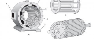
Any stator of a three-phase electric motor has three coil groups, which are otherwise called windings. One winding corresponds to one phase and has two outputs. They are the beginning and end of the coil, that is, there are six wires coming out of the engine in total, labeled as follows:
- C1 or U1 - the beginning of turn No. 1, C4 or U2 - the end of turn No. 1;
- C2 or V1 - the beginning of turn No. 2, C5 or V2 - the end of turn No. 2;
- C3 or W1 is the beginning of turn No. 3, C6 or W2 is the end of turn No. 3.
Motor terminal box
Please note! On conventional diagrams they are also signed with such letters, and they are indicated by wavy lines with three tubercles. You can verify this by looking at any three-phase motor connection diagram.
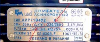
The coil cables are led out into a special terminal box of the engine. How these wires are connected determines the rated electric current supplied to the stator, as well as the power supply voltage.
Designation of coils in the diagram
What is phase rotation?
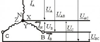
Phase alternation should be understood as the sequence in which the voltage increases in each of them. In all three-phase circuits, the voltage is a sinusoidal curve. In each line the voltage differs by 120º from the others.
Rice. 1. Voltage in three-phase network
As you can see, in Figure 1, where a) shows the voltage curves in all phase wires, shifted by 120º. The adjacent figure b) shows a vector diagram of these voltages. Both figures show the difference between phase and line voltage.
If we take as a basis that UA comes out from the zero point in figure a), then this phase is the first; in diagram b), the arrows clearly show that the order of voltage increase goes from UA to UB, and then to UC. This means that the phases alternate in the order A, B, C. This order of alternation is considered direct.
Direct and reverse phase rotation
In a three-phase network, the order of phase rotation may differ depending on the connection methods to power transformers at substations, the sequence of switching on the generator windings, due to mismatch of cable terminals and other reasons.
Figure 2: Forward and negative sequence
Please note that the color marking determines the sequence according to their order in the alphabet according to the first letters of the color:
- Yellow – first;
- Green – second;
- Red is the third.
Figure 2 shows the classic version of the forward sequence A - B - C (where A is yellow and is the first, B is green and is the second, and C is red and is the third) and the classic version of the reverse sequence C - B - A. But , in addition to them, in practice there may be other options, direct: B – C – A, C – A – B, and reverse alternation: A – C – B, B – A – C. Accordingly, in each of the above examples, phase alternation will start from the first one.
Determination method using a tester
Before you start work, you need to prepare your workplace. Follow all electrical safety rules and do not forget that working with electricity requires extreme concentration and accuracy. Let's do the work using the transformation method.
The work is performed in the following sequence:
- Using the tester, we find the terminals of the windings and mark them with cambrics, signing, for example, the first winding is marked C1-C4, the second C2-C5, the third C3-C6.
- We connect two windings in series. They are supplied with reduced voltage from the transformer.
- On the third, we will measure the voltage. When switched on, the tester will show some voltage. The value depends on the voltage level coming from the transformer. When turned on oppositely, the tester will show the minimum voltage value.
- We mark both windings accordingly.
- We disassemble the circuit and connect the third winding to any other. We supply voltage from the transformer and take measurements. The diagram is shown in the figure below. However, the circuit supplies a dangerous voltage of 220 volts. In our case, we supply reduced voltage from the transformer.
- By analogy with previous measurements, we determine the beginning and end of the third winding. Labeling.
- Once the wires have been identified and labeled, the motor can be connected in star or delta and connected to the network. In this case, the engine should not make increased noise and heat up. If this happens, you have made a mistake in determining the beginning and end of the windings. If everything is connected correctly, the engine runs smoothly and does not heat up.
A step-down transformer is needed to limit the current in the windings. You can do without it, but to limit the current, a low-power pilot light is turned on in series with the coils.
You should not take risks by supplying 220 volts to the windings without current limitation. In this case, there is a high probability of engine failure. Simply put, you can “burn” the windings.
Protection against alternation violation
To protect electrical equipment from incorrect rotation, a phase control relay is used in practice. This relay is configured to operate the engine or other device when it is connected directly. If due to some malfunction or incorrect connection the alternation is disrupted, the three-phase relay will immediately turn off the device. His work is based on the analysis of three-phase currents and voltages and subsequent monitoring of these parameters.
The connection can be made through current transformers or directly, depending on the model and voltage class of the network. Such protection has found wide application when connecting induction-type meters, electrical machines and other high-precision equipment.