About grounding
Before you do anything with electricity, you need to make sure there is a good grounding in your home.
You won’t be able to simply take and connect a regular household gasoline/diesel/gas generator to the electrical network at home. Precautions must be taken. The first is that your generator must be well grounded. Then you have a good chance of not getting an electric shock when the static from your favorite sweater penetrates the insulation of the generator winding. In general, you should not touch a running generator unnecessarily. It is worth remembering that the network is not always 220V. Switching on lines, lightning discharges in the distance, and static discharges produce such interference that short pulses of several kilovolts are not uncommon in the network. They combat this by installing arresters and surge protection devices at the entrance to the house, but this is a very rare practice in the Russian Federation. So let the spark go into the ground, and not through you - make good grounding throughout the house. Without this, you simply cannot do anything further!
About generators
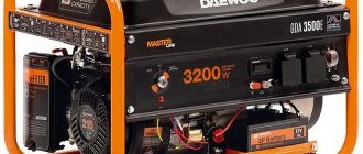
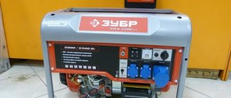
By the way, many household gasoline generators have windings that are not connected to ground in any way.
And this is quite normal when you are powering one power tool from a generator. But when you need to connect the generator to the house, you need to make a neutral wire (N) and a phase wire (L). To do this, one of the terminals of the generator is grounded and from this grounding point two wires must be independently led into the house - one will be the neutral N, and the second will be the protective ground (PE). When choosing a generator, you need to pay attention to whether its output can be grounded; sometimes this is prohibited in the instructions for the generator, then such a generator will not suit you. Often on the Internet you can see diagrams for connecting a generator without grounding and separating the N and PE lines. Don't do this, you'll live longer. Such schemes work well until the first unfortunate set of circumstances. Typical power supplies for modern electronic devices contain capacitors from lines L, N to ground. If N is not grounded at the generator, then due to these capacitors on line N there will be, if you're lucky, 110 volts relative to ground. By the way, many gas boilers stop working altogether in this mode. I already wrote above about the influence of statics without the presence of grounding.
Related links
- Rules for the technical operation of consumer electrical installations / Regulatory document dated February 9, 2007 at 02:14
- Electrician's Bible / Regulatory document January 14, 2014 at 12:32 pm
- Handbook on electrical networks 0.4-35 kV and 110-1150 kV. Volume 10 / Regulatory document from March 2, 2009 at 18:12
- Kabyshev A.V., Tarasov E.V. Low-voltage circuit breakers / Regulatory document dated October 1, 2022 at 09:22
- Rules for the installation of overhead power lines with voltage up to 1 kV with self-supporting insulated wires / Regulatory document dated April 30, 2008 at 15:00
- Knyazevsky B.A. Trunkovsky L.E. Installation and operation of industrial electrical installations / Regulatory document dated October 17, 2019 at 12:36
- Mankov V.D. Zagranichny S.F. Protective grounding and grounding of electrical installations / Regulatory document dated March 27, 2022 at 09:05
About AVR schemes
There are several different schemes for implementing ATS. Next I will write about the safest, from my point of view, single-phase ATS circuit. I do not advise economically making an ATS on one contactor or with switching only one phase wire. Only together with neutral.
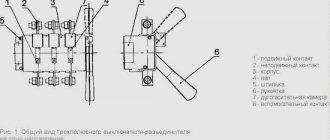
In the diagram shown, power from the network and from the generator is supplied through inputs 1 and 2. They are protected by paired circuit breakers. The switching and indication circuits are powered through additional circuit breakers. It can be seen that the relay coils are electrically interlocked. For the sake of simplicity, a microcontroller not shown in the diagram, which closes the circuits at the switching point TK1 or TK2, is responsible for turning on one or another input.
The fundamental point is the presence in the ATS of 2 interlocking circuits - mutual mechanical interlocking of the contactor switching inputs and mutual electrical interlocking of the contactors. In order to save money, home-made people sometimes neglect these blockings in their designs, but in vain. A circuit without interlocks can work for some time, but at some point the contacts will burn, the return springs will weaken and a short circuit will occur between the inputs. Firstly, it threatens a big bang if both lines are energized, but this is not the biggest problem. It is much more important that your generator, unexpectedly for the electricians repairing the wiring, can release voltage into the general network - in an unfavorable combination of circumstances, the electricians repairing the line may die. For you this is already a criminal article.
GOSTs and standards
Generator voltage regulator relay: diagram, principle of operation
GOST R 51732-2001 — Input and distribution devices for residential and public buildings. General technical conditions. https://docs.cntd.ru/document/1200008445.
GOST R 53471-2009 Three-phase synchronous generators with a power of over 100 kW. General technical conditions. https://docs.cntd.ru/document/1200080206.
GOST 5616-89 Electric hydroturbine generators and generator-motors. General technical conditions. https://allgosts.ru/29/160/gost_5616-89.
GOST 304-82 Welding generators. General technical conditions. https://allgosts.ru/29/160/gost_304-82.
GOST 29322-2014 (IEC 60038:2009) Standard voltages. https://docs.cntd.ru/document/1200115397.
GOST 13109-97 Electrical energy. Electromagnetic compatibility of technical equipment. Standards for the quality of electrical energy in general-purpose power supply systems. https://docs.cntd.ru/document/1200006034.
About contactors
Thus, the use of conventional relays is out of the question for us; only specialized contactors are suitable.
For higher powers there is also an option with motorized drives, but this is expensive and redundant for typical home use. To make a mechanical interlock, you need to select contactors that can work in pairs. Typically, mutual interlocking is achieved by installing identical contactors next to each other and installing an additional option - a mechanical interlock. It is sold separately from contactors and costs pennies.
Mutual electrical interlocking is possible if the contactor has additional signal contacts that operate to open. Sometimes they are immediately built into the contactor, sometimes they can be purchased and installed as an option.
Leading contactor manufacturers have such equipment in their lines. So finding and buying a kit is not difficult. True, prices for branded contactors are an order of magnitude higher than ours/Chinese ones. Since the number of switching cycles is not expected to be large, the choice of Chinese contactors is quite justified. The only disadvantage is that the contactor coils hum quite loudly during operation.
More about the switching power. The contactor contacts must be able to handle the maximum amount of power you are allowed to draw in your home. For me it is 10 kW, so I chose contactors for a permissible current through one contact of approximately 50 amperes. It is worth noting that for some reason the switched power for a typical three-phase contactor is indicated in the passport as the total for all three phases, so you need to carefully look at what the permissible current is through exactly one contact.
About the control scheme
When I was creating an AVR, I had several special requirements for its operation:
- My electricity doesn’t go out that often, so I decided that I didn’t need the autostart of the generator, but I decided not to give up the automatic stop of the generator: when the network is restored, the generator itself goes quiet and it’s immediately clear that now everything is fine with the power supply, and gasoline is saved
- After starting the generator, you need to give it time to warm up and only after warming up give it a load. Those. I needed a timer to turn on the ATS after applying voltage from the generator
- After the network voltage was restored, repeated outages often occurred after a short period of time, so I needed a timer that would wait a while before switching from the generator to the network and would not immediately turn off the generator
- They say it is useful for the generator to run a little without load before turning it off. And for this I also needed a timer
Thus, the picture emerged that I needed a controller with several timers.
At that time, I was interested in coding on AVR, so I decided to make such a controller on Atmega 8a. It would be nice if the controller worked for a long time and reliably. Besides, I couldn’t think of anything else to make a complete galvanic isolation and equip the controller with a watchdog timer. Well, make the diagram and program as simple as possible. Since I was doing everything for myself, I decided to leave all the settings and calibrations in the code - the entire UI was reduced to one LED)
The main task of the controller is to monitor the voltage at the inputs and, if necessary, switch the inputs. In this case, input from the village network has priority.
It is worth noting here that the quality of the network is such that fluctuations from 150 V to 250 V are quite common. Therefore, the concept of good mains power is very vague. After some time, I solved this problem when I installed one powerful 11 kW thyristor voltage stabilizer for the whole house. But, it’s important, the stabilizer can only be installed before the AVR, and not after! It is strictly not recommended to turn on the stabilizer for the generator. There is a danger that under a certain combination of loads, especially any powerful pumps, the system of a generator and stabilizer will become unstable and enter into self-oscillations.
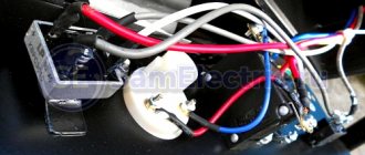
After some thought, I drew such a diagram in Eagle.
The circuit has two identical transformer power supplies; if there is voltage at any of the inputs, the circuit is provided with power. A voltage of 600V is possible between the inputs, so the insulation of the transformers must be good. Power is taken after the QF3 and QF4 packets, respectively.
Each source has a resistive voltage divider, protected from overvoltage by a zener diode - from it, the network voltage is measured using a microcontroller ADC using simple calculations.
To switch the contactor coils, a standard circuit from the datasheet is used to control semistores. 2 pieces ). Coils are an inductive load, so snubber circuits at the resistor and capacitor output are required.
I had a relay module with Ali that is used to stop the generator. In the diagram it is just a rectangle with three pins.
Among the features, the TL431 is also used as a reference voltage generator. Otherwise, everything is included as standard for Atmega 8. There are LEDs to indicate the presence of supply voltage at the inputs and one device status LED. The circuit is clocked using an external quartz at 16 MHz.
Eagle gave me this printed circuit board. No SMD, triacs and stabilizer with light radiators.
Two toroidal transformers are installed directly on the board. The board was made using the traditional amateur radio method using photoresist. After installation, I covered it with three layers of acrylic varnish. I hope the high voltage doesn't break through.
REQUIREMENTS FOR RESERVATION MACHINES
One of the main requirements for automatic transfer switches is the speed of switching to reserve.
A switch-on delay, during which there is no voltage, can cause failures in the operation of consumers, therefore, the shorter the switching time, the higher the reliability the redundancy system provides. The following parameters are taken into account:
- main and backup line voltage;
- number of switched phases;
- load power;
- the ability to automatically restore power from the main source after eliminating a power outage;
- delay in recovery;
- switching only if there is voltage from the backup source;
- switching blocking in case of short circuit in the load.
TYPES OF ATS – AUTOMATIC RESERVE TRANSFERS
Reservation machines are divided into several types:
- unilateral action;
- double acting;
- with automatic recovery.
Single-acting circuit breakers ensure operation of the load from the main source, connecting the backup one only in emergency situations.
Two-way backup machines can provide load operation from any line, considering it to be the main line and not the currently connected backup line.
Both one-way and two-way machines can be restored in the event of an emergency.
According to design options, AVRs are divided into:
- relay;
- relay with digital control;
- electronic.
Most of the systems used use a mechanical switching part in which the power lines are switched using high-power relays or contactors. The development of semiconductor technology has made it possible to use so-called solid-state relays, which do not contain mechanical parts.
Solid-state relays, subject to switching current limitations, are highly reliable, since there is no such thing as sparking during switching. The automatic backup system on the microprocessor control unit has the ability to quickly change the operating algorithm.
Such devices are equipped with a multifunctional indicator, which can display a number of monitored parameters:
- input status of the main and backup lines;
- load current;
- recovery delay time.