Description of the functions of the automatic generator engine start controller
Automatic engine start and stop - this function means that the generator engine will start automatically when the city network is turned off and connect your home to the 220 volt voltage that the generator produces. It will also correctly turn off the generator engine after the power supply is restored and switch your home to the city network of 220 volts (or 380 volts).
WINTER/SUMMER mode (engine warm-up 3 minutes) - this function is designed for generator operation in cold climates, in conditions of negative temperatures. When this function is enabled, after the engine starts, the object is not connected immediately to the generator, but after three minutes. During this time, the engine will have time to warm up a little and will not stall when a large load is connected to it.
Automatic switching of an object from the city network to the generator and back - when the generator autostart controller is operating, switching your home to a 220 volt network voltage or to the voltage generated by the generator will be carried out completely automatically, without human intervention.
“Double starter operating time” mode - this function is necessary for engines that start “with little difficulty.” For example, when to start the engine you need to increase the starter operating time.
ECONOMY mode (the cycle is repeated, 1 hour of engine operation - 1 hour of inactivity) - this mode is necessary when the power supply is stopped for a long time or when there is no power supply at all. The bulk of generators sold today are not designed for long periods of continuous operation - they can overheat and fail. This mode can save your generator from overheating and save fuel. You can also use rechargeable batteries in your power supply system, which will be charged when the generator is running and will release the accumulated energy when the generator is idle. In winter, this mode is simply necessary for houses where modern heating gas boilers are installed, which stop working when the 220 volt network is turned off. In the summer, this mode can be useful for operating refrigerators or refrigeration units.
Economy mode can be configured in any configuration. To do this, before purchasing, ask the seller for the mode you need. The following configuration may be useful: after a power outage - “5 hours of rest - 1 hour of work.” This operating option will save maximum fuel in winter and prevent your house from freezing.
Automatic “choke” control - the autostart controller controls a servomotor that is adapted to control the air damper. When the engine starts, the control circuit sends a signal to the servomotor and causes the damper to move in one direction or the other. The autostart controller changes the polarity on the wires that go to the servomotor at the right moments and thereby forces the damper to move in the desired direction. This control method does not require the installation of additional springs. The autostart controller can start both hot and cold engines without installing additional temperature sensors.
Engine start button “STOP TEST” – if there is a need to check the engine start, then you need to press and hold the “stop / test” button for more than 7 seconds. After this, the controller will start the engine. When checking the engine, the house will not be connected to the generator at all - only the engine is checked. When the generator engine is started and running, this button is already working to stop the engine. In this case, the engine is stopped in accordance with the recommendations of generator manufacturers (the engine is cranked without load for some time before stopping).
Automatic check of engine starting 14 days after the last start - as is known, when the engine is idle for a long time (a month or several months), the likelihood that this engine will start the first time decreases. The controller independently starts the engine for a short time (four minutes), thereby making the engine fully ready for further operation of the backup power system. A test start of the engine is performed automatically, at intervals of 14 days after the last engine start. During a test run of the engine, there will be no connection of the house to the generator at all - only the engine is checked.
Activating the automatic mode with the engine started manually (starting operation “on the fly”) - sometimes there are times when the generator engine can only be started manually (for example, when the starter battery is dead). If the engine is already started, the controller will not turn it off and start the engine again. The autorun controller will start working and correctly continue the operation of the entire system in automatic mode.
Cooling the engine before stopping (TURBO timer mode) – this mode is necessary for the engine to run without load before stopping. The engine runs for 40 seconds before stopping. After such a “soft” engine stop, the probability of a successful engine start the next time increases.
Among alternative energy sources, various types of electric current generators have become widespread. They are best suited for country houses and cottages, as well as other places where power outages often occur. In the event of a sudden loss of electricity, there is a need to quickly start a backup source in order to prevent disruption of the life support of the facility. Manual starting is quite complicated and requires special knowledge. Therefore, in such situations, as well as in the complete absence of people, the start function is performed automatically.
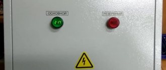
An automatic transfer switch for a generator, mounted on a special panel, is mainly used. This system allows you to turn on the unit and restore power supply in a matter of seconds. The working process involves two magnetic starters and a relay that controls the presence of voltage in the panel and the autostart system in the generator itself.
Characteristics of the Huter DY3000L gas generator
Here are a brief summary of the parameters of this gasoline electric generator that interest us as electricians: Output power - 2500 VA (taking into account the power factor and reserve - we take 2 kW), start - manual. In principle, you don’t need to know anything more from the electrical side.
The remaining parameters of the generator can be found in the instructions.
The instructions for the generator, as well as something else, can be downloaded by reading the article to the end.
The main power consumers are the heating system (about 300 W, in winter it is the most strategically important consumer, for which the generator was bought), TV (100 W), refrigerator (300 W), lighting (300 W). Total - we fit perfectly into 1.5 kW. To power such a load, this generator is quite enough.
The house also has a 2.2 kW electric heater and a washing machine, but I was given my word of honor that they would not be powered by a generator.
Generator design
The most important and capricious part of a Huter gasoline generator, like any other, is its starting system. The fuel valve, the air damper, the spark plug, the oil and gasoline levels - everything must be in the right position and normal.
What interests us is the engine operation switch (closed when turned off), AC and DC circuit breakers.
Below are a few photos of the electrical insides of the Huter 2500l generator:
1_wiring diagram Huter DY3000L_diode bridge and voltmeter
We see a KBPC3510 diode bridge with 35 Amperes and 1000 Volts. With a declared charge current of no higher than 9A, a maximum voltage of 14V and a circuit breaker current of 10A, the diode bridge will work without problems.
2_ wiring diagram of the Huter DY3000L gas generator _output terminals and protection
The second photo shows an alternating voltage circuit breaker, on which there is a sticker with information that its rated current is 12A, operation current is 15A. On the right is a 10A DC thermal relay.
3_ wiring diagram Huter DY3000L _operation switch
Design and principle of operation
A generator is an electric machine that converts mechanical energy into current electricity. In most cases, a rotational type of magnetic field is used for this. The apparatus consists of a relay, a rotating inductor, slip rings, a terminal, a sliding brush, a diode bridge, diodes, a slip ring, a stator, a rotor, bearings, a rotor shaft, a pulley, an impeller and a front cover. Often the design includes a coil with an electromagnet that generates energy.
It is important to note that the generator comes in AC and DC versions. In the first case, eddy currents are not generated, the device can operate under extreme conditions and has a reduced weight
In the second case, the generator does not need increased attention and has more resources.
The alternating current generator can be synchronous or asynchronous. The first is a unit that operates as a generator, where the number of rotations of the stator is equal to the rotor. The rotor generates a magnetic field and creates an EMF in the stator.
Note! The result is a permanent electric magnet. Among the advantages, the high stability of the generated voltage is noted; among the disadvantages, current overload is noted, since when the load is too high, the regulator increases the current in the rotor winding
The asynchronous device consists of a squirrel-cage rotor and exactly the same stator as the previous model. When the rotor rotates, the asynchronous generator induces an electric current and the magnetic field creates a sinusoidal voltage. Since it has no connection with the rotor, there is no possibility to artificially regulate the voltage and current. These parameters change under the electrical load on the starter winding.
Operating principle
Any generator operates according to the electromagnetic inductive law, due to the induction of electric current in a closed frame by the intersection of a rotating magnetic field, created using permanent magnets or windings. The electromotive force enters a closed loop from the commutator and brush assembly along with the magnetic flux, the rotor rotates and generates voltage. Thanks to spring-loaded brushes, which are pressed against the plate commutators, electric current is transmitted to the output terminals. Then it goes to the user’s network and spreads through electrical equipment.
Difference from synchronous generator
A synchronous gasoline generator is not overloaded due to transient conditions that are associated with starting under load from consumers of similar power. It is a source of reactive power, while asynchronous one consumes it. The first one is not afraid of overloads in the set mode thanks to the auto-regulation system through a connection that is inverse to the current with the voltage in the wire. The second has an artificially unregulated adhesion force of the electromagnetic rotor field.
Note! It is important to understand that the asynchronous version is more popular due to its simple design, unpretentiousness, lack of need for technically qualified service and comparative cheapness. It is installed when: there are no high requirements for frequency and voltage; the unit is supposed to operate in a dusty place; there is no opportunity to overpay for another variety
Principle of operation
In order to respond in a timely manner to possible difficulties in the operation of a gasoline generator, it is necessary to clearly understand the entire principle of its operation.
This knowledge will allow you to eliminate various problems, the risk of which is always present during operation.
For a better understanding, let’s outline the entire operating principle step by step:
- Fuel - gasoline - is poured into the corresponding crater of the fuel tank.
- After the device is connected to the network, fuel enters the engine through the gas line.
- As fuel enters the engine, it undergoes a special cleaning process to remove all kinds of impurities.
- Upon completion of this process, the fuel pump pumps gasoline into the carburetor.
- In the carburetor itself, gasoline is mixed to the required consistency. After this, oxygen is supplied to the fuel. As soon as the desired flammability is achieved, gasoline is supplied to the cylinders of the engine used.
- The engine starts. The fuel mixture is ignited by a spark from the spark plug. As soon as the fuel is burned, a gas formation appears, which triggers the crankshaft and piston system into action. The torque is transmitted to the rotor mechanism, which generates electrical energy from mechanical energy.
- The rotor mechanism rotates, which provokes the formation of a magnetic field, which, in turn, affects the occurrence of an electromagnetic field.
- The final result of the entire process is the generation of electrical energy.
In general, the power of the gas generator itself directly depends on the number of turns of the winding, so you need to keep this fact in mind.
The video shows the disassembly of a Firman gas generator and a story about its structure
Operating principle of industrial systems
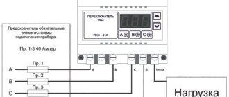
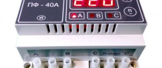
The basic principles here remain unchanged. As an example, we can take an ATS circuit in the form of a standard cabinet. A relay is used here to monitor the state of each phase. If there are problems on one of them with voltage imbalance, you can always switch the load to the remaining line. This will restore the original power supply when problems with the main source disappear.
Diagram of a typical industrial AVR cabinet
Designations:
- AB1, AB2 – three-pole protection devices;
- S1, S2 – switches for manual mode;
- KM1, KM2 – contactors;
- RKF – phase control relay;
- L1, L2 – signal lamps to indicate the mode;
- km1.1, km2.1 km1.2, km2.2 and RKF1 are normally open contacts.
- km1.3, km2.3 and RKF2 are normally closed contacts.
Huter gas generator diagram
Let's look at the electrical circuit of the Huter DY 3000L gasoline generator, which I took from the instructions:
Electrical diagram of a single-phase gas generator Huter
Briefly, how the gas generator circuit works. Alternator A2 is manually spun by a cable, ignition coil A5 produces a spark on spark plug F1, which starts the gasoline internal combustion engine. There will be no spark if switch SB1 is closed - the spark will be shorted to the housing.
Two output voltages of the alternator are generated - coil L1 220V (supplied through QF1 to the 220VAC output) and coil L2 - 12V (supplied to the output via the diode bridge and QF2). There is no direct current protection against short circuit; all hope for a short circuit is a large voltage drop.
You can monitor the oil level using the HL1 indicator, and the voltage level using the PV1 dial gauge.
Coils L3 and L4 are responsible for the correct operation of the alternator and the stability of frequency and voltage.
Idea
The idea is this: to place the engines parallel to each other. And the rotation is transmitted by means of a belt drive.
Before implementation, I decided to check how the motor from a lawn mower generates current. I rotate its shaft with screwdrivers.
As you can see, a 40 Watt 220 V incandescent lamp is used as a load. Of course, a screwdriver cannot produce the speed required for sufficient reproduction, but the multimeter shows a maximum of 156 Volts. But this is a preliminary result.
When should you contact the workshop?
A number of malfunctions, alas, are quite difficult to fix with your own hands without sufficient qualifications: for example, a faulty inverter converter or voltage regulator can be repaired only with a good understanding of the operating principle and circuitry of such devices. Not every owner of a gas generator will undertake to overhaul the engine, although this is not as difficult as it might seem.
In this case, you should contact a specialized repair shop. You can find out the coordinates of workshops in your city on the Internet or in stores selling gas-powered tools.
There are many such workshops in large cities, here are just a small part of them:
| City | Workshop | Coordinates |
| Moscow | "Electrical petroleum engineering" | 13 centers in Moscow and 18 in Moscow Region |
| "Southeast" | Maryino, Stavropolsky proezd. possession 199 (499) 390-93-49 | |
| Saint Petersburg | "Lenremont" | 7 workshops |
| "Benzomix" | st. Uchitelskaya, 23, ATOLL business center, office 154 (812) 385-54-30 | |
| Nizhny Novgorod | "Machines" | st. Rodionova, 24 |
| Novosibirsk | "RemCity" | st. Topolevaya, 3 |
| Vladivostok | "Gasoline unit" | st. Dorovolsky (4232) 273-273-9 |
The video shows the repair of a Chinese-made gas generator
Low voltage, and power circuits are working.
If the output power circuits are working properly, and the gasoline generator still produces low voltage, you should proceed to the next step - diagnosing the AVR generator voltage regulator. Diagnostics should again begin with a visual inspection of the voltage regulator unit. If burn marks are clearly visible on the AVR unit or if the capacitor is clearly swollen, then with a high degree of probability the reason for the absence or low voltage of the generator is hidden here.
What needs to be done: replace the voltage regulator unit with a new or working one. If you do not have the opportunity to purchase or borrow at least temporarily a known-good voltage regulator, you can read how to repair the AVR yourself using improvised means.
Tips for choosing a gasoline generator
The purpose of a generator with a brushless gasoline engine is to provide electricity to various objects. The unit copes with this task perfectly if you choose the appropriate model. There are various brands of generators on the market. Choose only those you are confident in. We do not recommend buying Chinese devices whose quality is in doubt. You should not save on a gasoline generator, because not only the functionality of the facility, but also the safety of its operation depends on its characteristics. Before purchasing equipment, determine the tasks that the unit will have to perform. Based on this, select the appropriate power.
- If there is insufficient power, the gasoline generator will be overloaded, which will lead to frequent breakdowns and a reduction in the operating life of the equipment. The unit will not work in this mode for a long time.
- If the power of the unit is too high, it will consume a lot of fuel to operate. The operation of such a unit will cost too long. There is no need to overpay for excess electricity that will not be used.
To avoid such situations, calculate the power according to this scheme:
- Determine which electrical appliances will be powered from an autonomous power source.
- Calculate the total power for all equipment.
- To the resulting figure, add 20-30% for the reserve.
When making calculations, do not lose sight of one important nuance - starting power. When starting a gasoline generator, the starting power will exceed the rated power for a short period. Once you have decided on the power, select a model based on other characteristics. Consider the following parameters: the presence of an automatic start system, the number of phases, voltage, the presence of additional power.
Operating principle of AVR
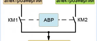
In low-voltage networks, it is convenient to use special relays that control voltage in protection circuits (ATS circuits, etc.). ATS is preferable here, since not all equipment can withstand frequent power supply switching. What does AVR look like? What is it and how does it work? This device is clearly visible from any simple diagram.
- Relay EL-11 controls three-phase voltage, monitors phase imbalance, breakage and alternation.
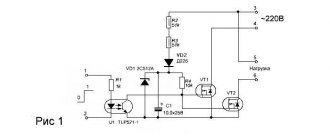
- Electromagnetic relays with powerful contacts are used to connect loads. In normal mode, the coil of the main input magnetic starter is powered from it and, with its contacts KM 1, connects the power supply to the load.
- When the voltage in the main circuit disappears, relay KM 1 is turned off and power is supplied to the coil of relay KM 2, which connects the backup input.
This ATS circuit can be used in private homes, industrial and administrative buildings, where the switched load reaches tens of kilowatts. The disadvantage of the scheme is the complexity of choosing a relay for high currents. It is still suitable for switching low-power consumers, but for heavy loads it is better to use an ATS starter or triac.
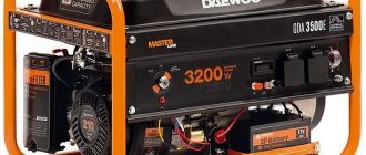
Gasoline or diesel generators are irreplaceable sources of additional power. The latter are widely used due to their efficiency and greater power. The market offers a wide range of diesel generator sets (DGS) containing protection systems against large overloads.
Engine
Gasoline generators are equipped with internal combustion engines. Manufacturers install 2-stroke and 4-stroke engines. Each variety has its own advantages. Two-stroke engines are inferior to four-stroke power units in terms of power, emit more harmful substances into the environment, and operate not on pure gasoline, but on a fuel-oil mixture. 4-stroke engines are more powerful and are equipped with a separate lubrication and cooling system. They have a large working resource and are able to provide electric energy to a dacha cooperative, cottage community, and construction site.
Inverter generator
An inverter generator has a completely different way of generating electrical energy, although it is still the same alternating current device.
It does not supply electricity directly, as happens in the classic model. Its design contains several intermediate components, the main one of which is the battery. How is electrical alternating current generated?
- At first, everything happens the same as in a classic device. That is, the internal combustion engine rotates a shaft that is connected to the alternator rotor. The latter produces alternating current.
- The current passes through the power electronics and becomes DC. They charge the battery.
- Now, in order to get alternating current again, an inverter is installed after the battery, which produces a current of the required voltage, or rather, 220 volts with a frequency of 50 Hz.
Why is such a complex scheme necessary, what is its advantage? Everything again comes down to hydrocarbon fuel consumption. For such a unit there is no need to maintain a constant rotor speed; it can be quite small, and this will be enough to charge the battery. True, with reduced rotation the charging time will increase
But in this case it is not so important. It turns out that the lower the rotation speed, the less fuel is consumed
Device classification
The classification of the device is extensive. Today it can be asynchronous and synchronous, with a fixed rotor or stator, single-phase, two-phase and three-phase, with independent or self-excitation, with field windings or excitation from a permanent magnet.
Note! It is worth noting that at the moment three-phase models are more popular due to the rotating circular magnetic field, the balance of the system, operation in several modes and high levels of efficiency.
Classification
Devices are divided according to their operating principle.
- One-sided. The circuit contains two sections: power supply and backup. The latter is connected when the main voltage is lost.
- Double sided. Any of the lines can be either working or backup.
- Recoverable AVRs. When the main power supply is restored, the previous circuit is automatically put into operation, and the backup circuit is turned off.
- No automatic recovery. The operating mode with the main power source is configured manually.
How to make your own AVR
Devices equipped with autostart are expensive, so it is recommended to assemble the ATS for the generator yourself, using the same elements as in factory models.
The main and most expensive part of the machine is the universal controller. Contactors are used as the power part, performing direct switching from the general network to the local network of the generator. To accommodate all the parts you will need a shield or cabinet that is most suitable in size for this device. The ATS circuit for the generator recommends using a special 1-3A control center as a power supply, and the switch should have three levels of operating modes. Electrical tools, cables and connectors should be prepared in advance.
To ensure high-quality assembly of the avr for the generator, it is necessary to follow certain recommendations and procedures. When choosing a controller yourself, you need to pay attention to the presence of an inverse air damper. This element is very useful for a generator equipped with a mechanical damper. When choosing contactors, you should focus on their throughput. If the device does not have electromechanical protection, it must be purchased separately.
In order to assemble an automatic transfer switch with your own hands, the circuit provides an automatic control device, which must have a normal constant voltage. The fulfillment of this condition is assigned to the power supply. Usually a high-power battery is used, since under heavy loads it discharges very quickly. This power supply regulates the output voltage. It is recommended to purchase all parts only from trusted specialized retail outlets, giving preference to products from the most well-known manufacturers.
Assembly begins with the installation of all parts and elements inside the electrical panel. Installation is carried out in such a way that there are no intersections of conductors with each other, and the contacts and terminals are accessible. For assembly, a diagram for connecting the ATS to the generator is used. After this, the controllers and power section are connected.
Serious attention should be paid to preventing parallel connection of the generator with the city electrical network. In this case, the unit may be seriously damaged, including complete failure. In order to avoid such negative consequences, it is recommended to use special switchboards that provide automatic or manual switching to automatic reserve input. These can be various types of high-current load switches or automatic generator voltage regulators.
When connecting, you need to take into account the presence of two cables included in the ATS shield. One of them belongs to the main network, and the other to the backup network. With different operating algorithms, they alternately switch. At the output, a single power cable is pulled to the consumers.
Connecting ATS
Before making the connection, it is necessary to correctly place all the parts in the electrical panel. They are installed in such a way that there are no crossings of conductors and free access to contacts and terminals is provided. After this, the power part of the ATS and controllers are connected in accordance with the circuit diagram.
Switching of the power part and controllers is carried out using contactors. After all connections, the ATS is directly connected to the generator. The correctness and quality of connections and connections of conductors and other elements is checked using a multimeter.
When using the normal mode, when the voltage is supplied from a regular power line, the automatic transmission system for the generator is activated in the ATS system and the first magnetic starter is turned on, supplying voltage to the switchboard of a private house. With the onset of emergency mode, in which there is no voltage in the network, a relay is used to turn off magnetic starter No. 1 and send a signal to the generator to perform autostart. After the generator starts operating in the ATS panel, the second magnetic starter is triggered, through which voltage begins to flow to the distribution panel of the home electrical network.
Operation in this mode will continue until the main supply of electricity appears or until the generator itself runs out of fuel. When the main voltage is turned on, the generator and magnetic starter No. 2 are turned off, and magnetic starter No. 1, on the contrary, is turned on, and the entire system returns to normal operation.
Installation of an automatic transfer switchboard is carried out after the electric meter. Thus, while the generator is operating, electricity consumption is not taken into account. In addition, the ATS shield for the generator is installed before the main switchboard of the home network. As a result, it ends up installed between the electricity meter and the distribution board.
If the total power of consumers available in the house exceeds the capabilities of the generator or the unit itself is not powerful enough, only those devices and equipment that are really necessary to ensure the normal functioning of the facility are connected to its line until the main power supply is turned on.
In this section you can find the circuit you need for a gasoline generator.
1. Typical wiring diagram for GX610 GX620 GX670 engines
2. Electrical diagram for engines like HONDA GX630 GX660 GX690
3. Electrical diagram of the generator GESAN G10000V, G10TFV
4. Electrical diagram of the HITACHI E100 generator
5. Electrical diagram of the Hyndai HY7000LE-3 generator
6. Electrical diagram of the Hyndai HY7000LE generator
7. Electrical diagram of the SKAT UGB-6000E generator
8. Typical diagram of 1 phase gasoline generator
Launch
The portable generator must be placed on a flat, dry surface, and if working in an open space, it must be protected from precipitation. Since single-cylinder engines used in gasoline-powered generators are characterized by a high level of vibration, foreign objects, and especially fuel containers, should not be placed on the generator to avoid them falling. Before starting, you must make sure that the engine oil level is sufficient and, if necessary, add it, after which the generator engine can be started.
The load can be connected to the generator only after the engine has been started. Do not run the generator while electrical appliances are connected to it.
To start a gasoline engine, a special air damper is used, which enriches the fuel mixture in the closed position. When starting the engine for the first time, especially in cold weather, it is necessary to close it more, the lower the air temperature, and gradually open it as the engine warms up. A warm engine should start without closing the throttle, otherwise you should pay attention to the carburetor adjustments. Starting, depending on the design of the engine, is carried out either by a cable starter (pull it out smoothly until you feel resistance, then sharply increase the force) or electric (to start, press and hold the start button). Starting a diesel engine differs only in that there is no need to use the air damper, but instead you need to slightly open the decompressor - a device that reduces the pressure in the combustion chamber to facilitate cranking during startup. In addition, starting a diesel engine can be made very difficult by an airy fuel system (the first start of a new generator or if the tank was previously run dry). In this case, you will have to bleed the fuel system (the bleeding procedure differs for different engines and is described in the operating manual). After letting the generator run for some time (in the warm season, the gasoline engine will warm up quite quickly, no more than a minute), you can connect the load, making sure that the performance indicators or voltage indicator of the generator set indicate its full functionality.
Emergency generator start
Sometimes it happens that the generator urgently needs to be started, but the manual starter fails at that very moment. If necessary, there are several methods for emergency starting.
The methods listed below are not safe!
Remove the starter housing. Below it is a flywheel with a cooling impeller, pulled to the crankshaft by a nut. To set it in rotation, you can:
- Wrap a rope around the flywheel and use it in the same way as a recoil starter cable. Please note that if it gets caught on the fan blades, when the engine starts, this rope will turn into a whip whipping in all directions, so be careful. Stand so that the rope cannot hit your hands or head.
- Low-power engines can also be started manually: with the ignition off, turn the crankshaft several times, rotating the pulley by hand in the desired direction. In this case, the gas tap must be open and the starter flap must be closed. After this, turning on the ignition, bring the crankshaft to compression TDC (you will feel an increase in force on the flywheel), and then turn the pulley with a sharp jerk so that the spark energy is enough to ignite the mixture.
- A powerful cordless drill and a head with an extension from the tool kit are a good quick replacement for an electric starter. Clamp the extension in the chuck, put a socket of a suitable size on it and unscrew the crankshaft by the flywheel mounting nut. True, in this way it will only be possible to start a low-power generator - for a large-volume engine, the torque of the drill is not enough to turn it on the compression stroke.
How to make a gas generator with a ready-made power plant?
The answer lies on the surface - connect the generator to a gasoline engine. Where can I get it? Any electric motor, with the correct organization of the winding excitation system, becomes a generator.
There are two directions for creating homemade generators:
DC generator
It receives torque from your car's engine and produces 14 volts of DC voltage.
There is no need to invent anything. Just look at the power characteristics and select a small engine from those listed above.
The main condition is a working voltage regulator and preferably “live” windings. However, if you get a burnt copy, it doesn’t matter. Any radio amateur knows how to remove the anchor from the electrical installation of a gas generator.
You can rewind the winding in one evening. In principle, if you can assemble a mini power plant yourself, you can sit down to write a book: “Gasoline generator malfunctions and ways to eliminate them.” This is an extremely useful experience.
A breakdown of a power source in an open field is a problem. And someone familiar with the Kulibin device will be able to restore operation without calling a technician.
The only drawback, however, is significant - the voltage is 12-14 volts. Lighting, charging mobile devices, connecting music and computer - no problem. But for the home you need 220 volts. A voltage converter will help out, for example, from an old uninterruptible power supply.
AC motor
Here the situation is more complicated (albeit cheaper, there is no need to look for a converter). Any electric motor can be turned into a generator by connecting it to a drive.
There are nuances. To excite the windings in generator mode, a capacitor circuit is required (see figure) and precise selection of speed.
If you have read this far, there is no point in explaining how to get one 220V phase from a 3-phase 380V source. This is the topic of a separate article.
To measure revolutions you will need a tachometer. You connect the motor to the network and measure the rotation speed. Add 5%-10% to the obtained revolutions, and you get the optimal shaft rotation speed for exciting the generator windings.
Device assembly diagram
You can assemble electric generators for 220 with your own hands by analogy with the production model. For this you may need video tutorials or tutorials. Then you need to correctly connect all devices of one system. This can be done using a star or triangle pattern.
In the first case, the electrical connection occurs for all ends of the windings of one point, and in the second case, a series type of winding generator connections is provided. It is important to note that these circuits can only be used if the phase load is uniform. Then the topic of how to make a generator at home will be relevant.
In general, a generator is a device that converts mechanical energy into electrical energy using a wire type of magnetic field coil. Depending on the number of phases, units come with one, two and three phases.
You can make it today with your own hands, using the special scheme indicated above.
The use of an electricity generator in the house can be done in 2 ways: by connecting electrical appliances directly to the unit’s outlet through an extension cord and by integrating the generator into the general electrical network of the room. If the first method is suitable for infrequent and short-term use (for example, in the country or in nature), then the second method is used during long power outages or in the absence of electricity at the site. In this article we will talk about generators as the main or backup power source in a country house or in any other building (in a store, workshop, production facilities) and about their correct connection.
ATS for generator: device, principle of operation, connection diagrams
Controlling the backup power supply by manual start is justified in many cases.
However, to ensure continuous operation of electrical equipment, there is a need for uninterrupted power supply. The relevance of the issue of automation of reserve input quite often comes to the fore. For this purpose, automatic transfer switch devices (ATS) are used. Modern ATS devices for generators are reliable devices that exclude human participation in managing backup power. Automatic control of the start of generators in the event of a network failure allows you to restore the supply of electricity almost instantly or with a slight delay. Thus, the continuous operation of electrical equipment is ensured, the stop of which may lead to undesirable consequences or provoke an emergency mode in the operation of the controlled system. Equipping diesel and gasoline generators with an electronic autostart unit is objectively a necessary measure to increase the safety of operation of individual electrical appliances.
Advantages and disadvantages
The Russian market offers autonomous power plants that run on diesel fuel, gas or gasoline. The latter are rightfully considered the most popular. Compared to other varieties, they have a significant list of advantages.
There are also disadvantages, and they must be taken into account when purchasing a gas generator. For example, buyers believe that using high-power gasoline units is unprofitable, since they consume a lot of fuel. In this case, it is better to opt for a model with a diesel engine. Other disadvantages: short time of continuous operation, susceptibility to breakdowns.
Sources
- https://SamElectric.ru/powersupply/ustrojstvo-i-shema-generatora-huter.html
- https://generatorexperts.ru/benzinovye/sxemu-benzogeneratorov.html
- https://piko-train.ru/devajsy/benzogenerator-iz-trimmera.html
- https://uk-parkovaya.ru/smarthouse/equipment/udarit-li-tokom-nol-benzogeneratora-na-220v.html
- https://tehnosadov.ru/articles/skhema-benzogeneratora/
- https://NpfGeoProm.ru/svarka/ustrojstvo-benzogeneratora-220v.html
- https://vmeste-masterim.ru/benzogenerator-220-volt-shema-jelektricheskaja.html
- https://generator-prosto.ru/s-nulya/elektricheskaya-shema-benzogeneratora-220v.html
- https://dmsht.ru/shemy-generatorov-220v-benzinovyy/
- https://papakarlotools.ru/articles/233859/
- https://rps-spb.ru/services/electrical-circuits/
