The uninterrupted operation of the energy system is not always permanent. Natural or man-made external factors can make adjustments to its functionality. Taking this into account, pantographs (first and second reliability categories) are connected to more than two power sources. The load when switching to the main and backup power sources increases, therefore, for reliability, an ATS system (automatic transfer of reserve) is used.
- Simple circuits
Purpose and what is an AVR
The ATS system - an electrical switchboard input and switching switchgear - quickly switches the load to a backup source if problems arise with the energy plan on the main line. Before automatically switching to emergency operation, the system detects voltage problems in the input circuit and problems with the loads.
What is hidden under the abbreviation?
There are many ways to improve the operation of the energy supply system of buildings and residential buildings. Among them, AVR is of particular importance. The name ATS - automatic transfer of reserve - explains the purpose of the system. Sometimes “input” is replaced with “turn on,” which is not entirely correct. Turning on a reserve means starting a backup generator in certain cases.
Typical AVR panel
AVR classification
The principle of classifying the operation of the working system allows us to identify the most complex sections of the voltage supply circuit. ATS blocks or cabinets are usually classified according to certain parameters:
- by the number of reserve sections (for example, ATS for two supplies to ensure greater reliability of power supply);
AVR cabinet for three inputs - by network type (usually single-phase ATS units are used, but there are devices for switching three-phase power that are used to start a generator);
Application of AVR in a private house
- by response time;
- by power of switched load;
- by voltage class (for example, in circuits for switching high-voltage lines).
The classification serves as a clear example of the operation of an energy supply system with control of switching from the primary source to the backup one. ATS speeds up and protects automatic switching.
What are the requirements for AVR?
To restore power supply in emergency situations, an ATS system that meets certain requirements is used.
- Ensuring uninterrupted power supply from the backup input in case of problems on the main line.
- The ability to restore the operation of the power supply system in the shortest possible time.
- One-time connection and disconnection of the load (for any reason).
- The process of transferring from the main power source to the backup unit is controlled by the ATS system before connecting to the reserve.
- The ATS system monitors the serviceability of the backup equipment control.
Automation selection
PromEnergo AVR unit
Industrial equipment and professional equipment are equipped with automatic equipment as standard. At a minimum, they offer a box with a set of contactors to reproduce the protective algorithm. An emergency button is placed in the accessibility zone. If necessary, the unit can be turned off by hand in one quick movement.
A specialized AVR shield can be purchased assembled or you can create a functional analogue yourself. When choosing a finished product, you should pay attention to the reputation of the manufacturer. A preliminary study of customer reviews and the opinions of experienced experts will be useful.
In the lower price range there are products of dubious origin. If a single-phase ATS costs up to 1500-2000 rubles, you can hardly count on a long service life and high reliability. Counterfeits are characterized by poor assembly and low quality contact groups. Quite often, such models use low-power electronic switches that are not adapted to voltage surges and loads with pronounced inductive characteristics.
From 4,000 to 8,000 rub. you can find high-quality AVRs from little-known brands. Reliable equipment sets use electromechanical functional components.
In the range from 20,000 rub. and above are products from responsible manufacturers. These products are provided with official warranties. Performance and other important parameters are monitored in each individual product batch.
Automation without controller
The decoding of the designation emphasizes the main feature of equipment in this category. The “automatic” method of connecting a modern level of reserve implies not only the absence of user intervention. The electronic controller provides quick check of the state of the supply and backup networks. It blocks erroneous operations and prevents the occurrence of potentially dangerous situations. When choosing an ATS, you should check whether this useful component is included in the kit.
ATS in 0.4 kV networks
To switch power circuits in networks with relatively low voltage (0.4 kV), serial contactors with a magnetic drive are used. Starters are also used complete with AB. Circuit components are selected taking into account current loads (power consumption).
In typical ATS switchboards with 2 inputs, electricity metering devices, surge protection devices, and relays with a delay function are installed to create an additional time interval before connecting the load.
How does the AVR work?
There are two types of system that differ in the type of input:
- Single-ended type ATS , where there is one working input, used until problems with the main line disappear. The system has a second - backup - input, which is connected in cases of emergency.
- A double-sided ATS does not have a separation based on operating and backup principles, since both inputs are a priority.
The first type is characterized by the presence of a function that makes it possible to switch to the operating mode as soon as the main mode is restored. The two-way type of ATS has its own advantages, so such a function is not provided there. And in the second case, there is no fundamental difference from which source the load comes.
You can see examples of both one-way and two-way operation of the ATS system.
System requirements
The main requirements for ATS systems are:
- Performance.
- Reliability of inclusion.
- Supply voltage only if there is no short circuit in the area, that is, there must be a blocking in the event of a short circuit.
- One-time operation.
- The ability to adjust the threshold for turning on the backup power supply so that it does not work, for example, during voltage sags during the start of powerful electric motors.
- Operation only if there is electricity at the backup input.
Naturally, the simplest circuit using contactors will not be able to implement all the requirements for the ATS system. For this purpose, modern electronics use logical systems that send a signal to turn on the backup power source only if all rules and interlocks are observed. Also, for additional reliability, a mechanical lock is even used.
On what basis does automatic reserve entry take place?
Regardless of the type of connection on a one-way or two-way basis, the system has a function for monitoring network parameters. For these purposes, a voltage control relay is used, as well as microprocessor control units, which does not affect the operation of the system as a whole. For example, you can consider the principle of operation of an ATS to ensure uninterrupted power supply for a single-phase consumer.
A simple circuit of a single-phase ATS
Designations:
- N – Zero.
- A – Working line.
- B – Backup power supply.
- L – Lamp acting as a voltage indicator.
- K1 – Relay coil.
- K1.1 – Contact group.
In normal mode, voltage is supplied to the indicator lamp with relay coil K1. Thus, the position of the normally closed (and normally open) contact changes. The load comes from the main source, line A. Voltage B disappears at input A, the lamp goes out, and the relay coil stops saturating, which, accordingly, leads to the contacts returning to their initial position. Thus, the load is switched on at input B.
When the voltage is restored at the main input, the relay is re-switched to source A, which corresponds to the principle of operation of a single-sided source.
This is a simplified diagram illustrating the processes occurring in the automatic transfer system, which is usually taken as an example for explanation.
Design and principle of operation
Regardless of the device for automatically switching on the reserve, its fundamental task is to monitor the parameters of the electrical network. For this purpose, voltage monitoring relays or units equipped with microprocessors can be used. There are two main types of device:
- One-way (OAVR) - one input works as the main one and is used until problems arise in the electrical main. The other acts as a backup and is switched on in emergency situations.
- Double-sided (DAVR) - both inputs perform the main work and are used as a reserve.
The design itself is a cabinet or ATS panel with contactors or automatic machines. Often in practice, designs with restoration are used, that is, as soon as the main network returns power, the backup power is turned off.
You may be interested in Features of measurement in lumens and watts
In the event of a voltage drop in the controlled section of the circuit, the relay sends a signal to the ATS circuit. The absence of voltage in the network alone is not enough for the switching device to operate. For this, a number of other conditions must be present:
- There should be no short circuit in the area being tested, since turning on the backup power will be impossible and unacceptable.
- The input switch must be turned on so that in the absence of voltage the ATS does not accidentally start.
- The area from which the reserve will be powered must have voltage.
When all conditions are met, the transfer switch sends a signal to turn off the input switch of the de-energized network and turn on the ATS. The algorithm of actions occurs strictly in this order, that is, without disconnecting the input, the backup power will never turn on.
What schemes of operation of ATS exist?
Working examples show the success of using an autostart panel for uninterrupted power supply to a home.
Simple circuits
One of the variants of the ATS circuit shows the switching of electricity to the generator from the main line. The principle of short circuit protection is present here. This ATS is equipped with electrical and mechanical interlocking, which prevents two inputs from starting at the same time.
AVR diagram for home
Designations:
- AB1 and AB2 are two-pole circuit breakers on the main and backup inputs.
- K1 and K2 are contactor coils.
- K3 – contactor acting as a voltage relay.
- K1.1, K2.1 and K3.1 are normally closed contacts of the contactors.
- K1.2, K2.2, K3.2 and K2.3 are normally open contacts.
When automatically switching AB1 and AB2, the operation of the ATS system is as follows:
- Power supply from the main line is normal. When coil K3 is saturated, the voltage relay is triggered, which leads to the closure of K2.2 and K2.3 and the opening of K1.
- Power supply in emergency mode. If there are voltage problems on the main line, K3 is not saturated, the voltage drops below the permissible level, and the contacts return to their original position. Thus, voltage is supplied to coil K1, which causes the position of contacts K1.1 (the role of electrical protection) and K1.2 (which removes the blocking of power supply to the load) to change.
- Mechanical interlock triggered. In this case, a reversing starter is used (if there is one on the design of the electromechanical device).
An example of the operation of two simple automatic transfer switches for three-phase voltage, where, in one case, power supply is carried out according to a one-way scheme, and in the other - according to a two-way principle.
An example of one-way (B) and two-way (A) implementation of a simple three-phase ATS
Designations:
- AB1 and AB2 – three-pole circuit breakers;
- MP1 and MP2 – magnetic starters;
- RN – voltage relay;
- mp1.1 and mp2.1 – group normally open contacts;
- mp1.2 and mp2.2 – normally closed contacts;
- rn1 and rn2 – RN contacts.
Circuit A has two equal inputs to prevent simultaneous switching of lines. The principle of mutual interlocking is used here, as on contactors MP1 and MP2. Thanks to the sequence of automatic switching on AB1 and AB2, it will depend on which line the load will go. If AB1 is triggered first, then the MP1 starter is activated, and the MP1.2 contact is broken, which leads to the blocking of voltage to the MP2 coil. If source 1 is turned off, then the MP1 starter goes to its original position. And PM2 comes into action, which blocks the first starter and transfers the load supply from source 2. You can also switch sources manually using AB1 and AB2.
For the one-way principle of operation, circuit B is used. Its main difference is that a voltage relay (RN) is added to the connection circuit and when operation is restored, it returns the connection to source 1. But at the same time, RN2 opens, which turns off the starter MP2 and closes RN1, which allows you to connect MP1.
How does automatic backup power input work?
The principle of operation of the ATS is based on monitoring the voltage in the circuit. This can be done using any voltage relays or digital logic protection blocks. However, the principle of operation still remains unchanged. Let's look at it using the simplest example.
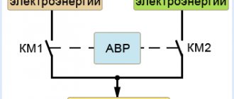
This is a single-line diagram, which shows that the presence of voltage is monitored by the KM contactor. Both automatic machines QS1 and QS2 must be turned on, in which case the KM coil will receive power and be drawn in, and accordingly its closing contact in the main input circuit is also closed and the breaking contact in the backup input circuit is open. Thus, the consumer is supplied with electricity from the main network and the corresponding lamps are lit. In the event of a power failure on line L12 and the voltage drops to a value when the KM contactor turns off, the closing contact in the main line will open and at the same time the contact in the backup power circuit of line L22 will go into the closed state, thereby supplying voltage to the consumer from the backup source . The opposite situation will occur when the main power supply is restored via line L12.
The video below clearly examines the operating principle of ATS in 6 kV networks:
Operating principle of industrial systems
The basic principles here remain unchanged. As an example, we can take an ATS circuit in the form of a standard cabinet. A relay is used here to monitor the state of each phase. If there are problems on one of them with voltage imbalance, you can always switch the load to the remaining line. This will restore the original power supply when problems with the main source disappear.
Diagram of a typical industrial AVR cabinet
Designations:
- AB1, AB2 – three-pole protection devices;
- S1, S2 – switches for manual mode;
- KM1, KM2 – contactors;
- RKF – phase control relay;
- L1, L2 – signal lamps to indicate the mode;
- km1.1, km2.1 km1.2, km2.2 and RKF1 are normally open contacts.
- km1.3, km2.3 and RKF2 are normally closed contacts.
Complete set of cabinet and panel
The configuration and operating rules of backup power input cabinets of types AVR-RN, AVRPA, AVRR are practically no different from each other. The device is a rectangular welded product with two doors.
There are two panels mounted inside on which power and control devices are installed. When operating in networks with currents up to 100 A, cabinets made on the basis of PM 12 starters with silver contacts are used.
For currents above 100 A, vacuum contactors are installed. All connections of input and output circuits are made with a tool that ensures stable contact. Clamps designed for connecting stranded copper and armored wires with lugs are installed in the cabinet.
Installed starters must be designed for 300 thousand operations, and the shutdown time of the machines during a short circuit does not exceed 0.05 seconds. All devices must have appropriate symbols, and additionally, explanatory tags must be installed under them.
Cabinets usually have two cable entries: for the supply and backup wires, which are connected to pin blocks . The power part includes:
- power input block;
- output blocks connected to the corresponding machines;
- two input contactors;
- two voltage transformers.
You might be interested in Automatic switch ABB 16A
The light indicators are powered by a voltage of 36 V. The installed AVR time relays provide the transformers with an uninterrupted supply of electricity. The equipment control system includes circuit breakers, warning lamps and phase control relays. The assembled cabinet can be used in conditions that exclude precipitation and at temperatures from - 45 °C to + 45 °C.
High-voltage circuits with ATS
The operation of automatic transfer switches in high-voltage networks of the 1 kV class has a more complex scheme, although with a similar operating principle, as stated above. All triggering mechanisms do not change here. But in this scheme there are no backup transformers and each bus (Sh1 and Sh2) is connected to its main supply transformer (T1 and T2). The latter can, in certain circumstances, become backup sources with additional load. In normal mode, the CB10 switch is open and the ATS controls the TP via TN1 Ш and TN2 Ш.
When the power is blocked at Sh1, B10T1 is turned off and SV10 is turned on. Both sections or blocks start working from the same transformer. As soon as the source restores its operation, the ATS will reconnect the system to its original position.
Simplified diagram of 110/10 kV transformer substation
Classification of ATS and implementation options
The following schemes for organizing working algorithms are used:
- One-way means connecting a backup input if necessary. For example, for temporary power supply from a battery.
- In the double-sided design, both sections are equivalent. This solution is used if switching to a backup network with similar parameters is possible.
The logic of the restoration process is separately determined. Use:
- subsequent automated connection to the main line;
- switching to backup power with manual mode change.
Features of working with household generators
The popularity of this solution is due to the ease of choosing equipment with the required power. In the corresponding market segment, they offer generators driven by gasoline (diesel, gas) engines for connection to single- and three-phase networks. They are designed for long-term continuous operation without careful supervision. Autonomy actually depends only on the fuel supply.
To start the power unit, the sectional automation cabinet is equipped with a specialized control unit. It supplies power to the starter according to the established algorithm. In particular, you can configure the program to preheat the diesel engine in winter conditions.
Battery-powered ATS
These backup power supplies supply direct current to the line. An inverter is used to convert it to a sine wave of a certain amplitude (220 or 380 V). You should understand the limited autonomy of this option. However, parallel connection of several batteries can provide the required time interval. A promising direction is lithium-ion energy storage devices. They are superior to lead-acid analogues in their main technical characteristics. The high price limits widespread use. However, as demand increases and production expands, manufacturers are beginning to offer quality products at reasonable prices.
Connecting a battery is simpler compared to a generator. In this version, the ATS can be assembled according to a standard scheme without a special engine start control unit.
Application of Logic Controller
Such blocks are used to fine-tune the algorithm of work operations. Special regulators set the permissible percentage of voltage deviation from the nominal value, time intervals, and other parameters. The control signal circuits are connected to switching devices.
Organization of automatic transfer switches in high-voltage circuits
To simplify monitoring of network operating parameters, a step-down transformer is used. A certain number of turns reduces the voltage from 1000 to 100 V. If a phase control relay is added to the control circuit, the reserve is connected when at least one line breaks.
How microprocessor-based contactless systems work
ATS of this type have microprocessor control units. In operation of the device, the connection is made through semiconductor switches, which are more reliable.
Electronic unit AVR
Contactless automatic transfer switches have many advantages:
- There is no need for mechanical contact and there are no problems that can arise with it (burning or sticking, etc.).
- There is no need for mechanical locking.
- There is an extended range of control over all switching parameters.
The disadvantages include the difficulty of repairing an electronic type AVR. Implementing such a device scheme yourself will be problematic. You cannot do without special knowledge of electronics and programming knowledge.
With AVR water, the load on the operation of the entire system is significantly reduced, there will be fewer blockages, but it is easier to control the processes of switching electricity from the main source to the backup one and vice versa. Connection diagrams can always be found on the Internet or in the instructions.