V - shaped characteristics of a synchronous motor.
Synchronous compensator.
The synchronous compensator is a synchronous motor running without load on the shaft; in this case, almost only reactive current passes through the armature winding. The synchronous compensator can operate in cos φ improvement mode or in voltage stabilization mode.
Rice. 6.55. Vector diagrams of a synchronous compensator: a - in the network cos φ improvement mode; b, c, d - in voltage stabilization mode.
Starting a synchronous motor.
Due to the lack of starting torque in a synchronous motor, the following methods are used to start it:
Start with auxiliary motor.
Asynchronous engine start.
Start with auxiliary motor.
Starting a synchronous motor with the help of an auxiliary motor can only be done without a mechanical load on its shaft, i.e. almost empty. In this case, during the start-up period, the engine temporarily turns into a synchronous generator, the rotor of which is driven by a small auxiliary motor. The stator of this generator is connected in parallel to the network in compliance with all the necessary conditions for this connection. After connecting the stator to the network, the auxiliary drive motor is mechanically switched off. This starting method is complex and also has an auxiliary motor.
Asynchronous engine start.
The most common method of starting synchronous motors is asynchronous starting, in which a synchronous motor is converted into an asynchronous one for the duration of the start. To enable the formation of an asynchronous starting torque, a short-circuited starting winding is placed in the grooves of the pole pieces of a salient-pole motor. This winding consists of brass rods inserted into the grooves of the terminals and short-circuited at both ends with copper rings.
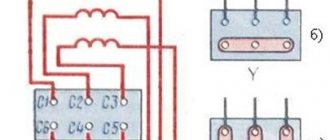
When the engine is started, the stator winding is connected to the alternating current network. The excitation winding (3) is closed to a certain resistance Rg for the start-up period, Fig. 45, key K is in position 2, resistance Rg = (8-10)Rv. At the initial moment of start-up at S = 1, due to the large number of turns of the excitation winding, the rotating magnetic field of the stator will induce EMF E in the excitation winding, which can reach a very large value, and if the excitation winding is not turned on at the start-up, insulation breakdown will occur at resistance Rg.
Rice. 45 Fig. 46.
The process of starting a synchronous motor is carried out in two stages. When the stator winding (1) is connected to the network, a rotating field is formed in the motor, which will induce an EMF in the short-circuited rotor winding (2). Under the influence of which current will flow in the rods. As a result of the interaction of the rotating magnetic field with the current in a short-circuited winding, a torque is created, like that of an asynchronous motor. Due to this moment, the rotor accelerates to a slip close to zero (S = 0.05), Fig. 46. This ends the first stage.
In order for the motor rotor to be pulled into synchronism, it is necessary to create a magnetic field in it by turning on direct current in the excitation winding (3) (by switching key K to position 1). Since the rotor is accelerated to a speed close to synchronous, the relative speed of the stator and rotor fields is small. The poles will smoothly overlap each other. And after a series of slips, the opposite poles will attract, and the rotor will be pulled into synchronism. After which the rotor will rotate at synchronous speed, and its rotation speed will be constant, Fig. 46. This ends the second stage of the launch.
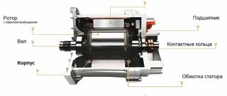
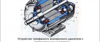
Structural elements
The synchronous electric drive device is based on the use of the properties of three-phase current to create a rotating magnetic field. Therefore, its design includes the following main parts:
- inductor wheel (or inductor, stator) – stationary motor unit;
- rotor (or armature) is a moving mechanism.
Each component consists of a number of smaller elements that closely interact with each other. The inductor has a structure similar to an asynchronous drive and contains:
- frame;
- ball bearings supporting the armature;
- supports that fix the position of the bearings and are the completion of the housing;
- a fan designed to cool the electric motor;
- a casing used to protect against a rotating fan.
Additionally there is a box for electrical connections, which is located on the side of the stator housing. The body contains a laminated metal core. The term “laminated” means a set of thin (0.3-0.5 mm thick) steel plates insulated from each other. The outer strips have stamped grooves for phase windings.
The dimensions and design of the inductor wheel can be different: in the form of a solid cylinder or assembled from individual cylinder segments. The design of the housing depends on the power and dimensions of the electric motor. For small machines, a one-piece product with a pressed-in stator is made; for powerful electrical equipment, a prefabricated version is provided. This simplifies transportation, installation at the workplace and operation of the electric motor.
The rotor mechanism is designed to excite a synchronous motor (SM), therefore it contains a core either with permanent magnets (for low-power electric drives) or with electromagnets. Similar to an inductor, the rotor can be assembled or solid. For a motor designed for high speeds (3000, 1500 rpm), the rotor winding is evenly distributed over the surface of the cylindrical armature. Such an electric drive is called non-salient-pole. A low-speed LED (up to 1000 rpm) has poles with excitation coils on the rotor, so it is called salient-pole.
In a non-salient-pole synchronous motor, the armature is a steel cylinder, along the length of which there are grooves for laying the rotor electrical circuit. Depending on the design, it can be forged directly connected to the shaft, or be a separate product pressed onto the shaft. To protect against centrifugal force, the excitation system of the synchronous drive is covered with non-magnetic steel rings.
An electric motor with a salient pole rotor has a different arrangement of armature circuits. In this case, the armature has a magnetic circuit attached to the machine shaft. On the magnetic circuit there are poles with pole pieces on which the electric rotor winding is located. The excitation system of a synchronous electric motor also contains connecting elements in the form of rings installed on the shaft, and stationary electric brushes pressed against them.
As the rings rotate, they slide along the brushes, providing sliding electrical contact. A similar brush assembly has an asynchronous electric motor with a wound rotor. The only difference is the number of slip rings and brushes. The phase winding of the armature of an asynchronous machine requires three slip rings, while a synchronous machine requires only two.
V-shaped characteristics
V-shaped characteristics represent the dependence of the armature current I
and the power factor
cosj
of the motor from the excitation current i
in
at constant values of the armature winding voltage U
and
its frequency f
and
constant output mechanical power P2
.
These characteristics reflect an important feature of synchronous motors
- the ability to regulate their reactive power and cosj
.
Let's consider the V-shaped characteristics of motors using the example of a non-salient pole machine. The necessary explanations are given using simplified vector diagrams of a synchronous motor presented in Fig. 12.3.
If we accept losses in the winding and armature steel, mechanical and additional losses as constant, then at P
2= const the power supplied to the armature winding is also constant,
P
1=
mUIcosj
= const, and, therefore, the active component of the armature current is also constant -
I
a=
Icosj
= const.
Therefore, in the vector diagram (Fig. 12.3), the end of the armature current vector I
at different values of the excitation current
i
in slides along straight AB.
For each value of I,
the value
of iв
can be determined from the current equation of a synchronous machine, reflecting the MDS equation.
Thus, iв
d represents the resulting MMF in the gap
Fd
on the excitation current scale,
I¢
is the MMF of the armature reaction
F¢
a on the excitation current scale or the reduced armature current.
The excitation current is directly proportional to the MMF F
in the excitation winding.
Value iв
d can be determined from the resulting emf
E
d of the armature winding induced by the resulting magnetic field of the air gap.
If we neglect for simplicity the leakage resistance x
sa= 0 and the active resistance
r
a= 0, then and, trace -
Rice. 12.3. Simplified vector diagrams of a synchronous motor
specifically, i
вd »
const
.
The vector, like the vector of the resulting flow in the gap, is 90° ahead. The vector coincides in direction with the armature current, and its end slides along the straight line A'B', parallel to the line AB, since I'
is directly proportional to the armature current.
In Fig. 12.3 vector diagrams of currents are plotted for four points V
-shaped characteristic and the excitation currents for the corresponding armature currents were obtained.
For point 1 in Fig. 12.3, a vector voltage diagram was also constructed according to the equation, where E
is the emf induced in the armature winding by the field of the excitation winding;
x
c is synchronous inductive reactance.
Main types of diabetes
Classification of synchronous motors can be made based on various factors. Depending on the operating mode, electric drives are:
- electromechanical drives – motor modes;
- generator devices – generator mode.
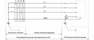
The section above discussed how a synchronous motor works in motor mode and what structural elements it consists of. The design of the generator is similar, the difference lies mainly in the operating mode. The connection diagram with a synchronous generator for operation in conjunction with the network is shown in the figure:
The synchronous type generator is a symmetrical three-phase source of electricity. It converts the mechanical energy of the drive mechanism into electrical energy of three-phase current. An electricity consumer is connected to the generator inductor, or the stator is connected to the electrical network for joint parallel operation with other three-phase units. The excitation winding of the generator, connected to the mains supply (exciter) with a voltage of 220V (or other parameters), creates a constant magnetic flux, which is closed in the magnetic circuit of the LED as follows:
The operating principle of a synchronous motor, its power, and connection diagram form the basis for the construction of various electrical units. In this regard, the following types of synchronous machines are distinguished:
- a hydrogenerator that generates electricity from hydraulic turbines;
- a turbogenerator operating in conjunction with a steam or gas turbine;
- electrical equipment to increase the power factor of electrical installations or to stabilize the voltage in the network;
- shock generator, used for short-term use in short circuit mode;
- dual power installation providing non-synchronous operating modes;
- A selsyn, which is a low-power device that performs the functions of a rotation angle sensor.
These are not all technical installations where different types of synchronous devices are used.