Electric machine excitation systems (Fig. 5.1), produced by factories more than 30 years ago and still in operation, can be replaced with modern semiconductor static systems with any set of specified functions.
Excitation systems provide the following operating modes of synchronous machines:
- initial excitement;
- idling;
- connection to the network using the method of precise synchronization or self-synchronization;
- work in the power system with permissible loads and overloads;
- forcing excitation in voltage and current with a given multiplicity;
- reactive power unloading and deexcitation during disturbances in power systems;
- extinguishing the generator field in emergency modes and during normal shutdown;
- electrical braking of the unit.
Fig.5.1. Independent excitation system with DC exciter. КК – slip rings, Rсс and КСС – resistance and self-synchronization contactor, РВ – reserve exciter, АГП – automatic field extinguishing device, AGPV – automatic extinguisher field extinguishing device, Rр – adjusting rheostat, Rд and Rгасв – additional and quenching resistors in the OVV, DOVV circuit – additional excitation winding of the exciter.
To equip turbo and hydrogen generators, three types of excitation systems are produced: • independent thyristor systems (STN) – Fig. 5.2; • thyristor self-excitation systems (STS) – Fig. 5.3; • brushless diode systems (BDS) – Fig. 5.4
Thyristor independent excitation systems (STN)
Independent thyristor systems (STN) are designed to power the excitation windings of large turbo and hydrogen generators with rectified controlled current, used in generating electricity at hydroelectric power stations and other generating stations - Fig. 5.2.
Abrahamyan Evgeniy Pavlovich
Associate Professor, Department of Electrical Engineering, St. Petersburg State Polytechnic University
Unlike self-excitation systems (SES), in STN the thyristor rectifiers of the main generator receive power from an independent power frequency AC voltage source - from an auxiliary synchronous generator rotating on the same shaft as the main generator
Fig.5.2. An independent thyristor system (STI) with an AC exciter and two groups of thyristors, in combination with a backup excitation circuit from a two-machine unit - an asynchronous motor-DC exciter. B – exciter (auxiliary generator) of alternating current, OVV excitation winding of the exciter, VRG, VFG – thyristor valves of the working and forcing groups, VVV – thyristor valves of the exciter rectifier, SUVRG, SUVFG, SUVVV – control systems for the valves of the corresponding groups, VTV – exciter rectifier transformer , TSNV – transformer MV of thyristor rectifiers.
The auxiliary excitation alternating current generator is built according to a self-excitation circuit. STN has an important advantage - its parameters do not depend on the processes occurring in the power system.
Vasiliev Dmitry Petrovich
Professor of Electrical Engineering, St. Petersburg State Polytechnic University
Thanks to the presence of an auxiliary generator, the excitation remains independent of the duration and distance of the short circuit and other disturbances in the power system, and the high rate of increase in the excitation voltage: no more than 25 ms until the maximum value is reached when the positive sequence voltage at the control point decreases by 5%.
The STN system ensures rapid de-excitation by changing the polarity of the excitation voltage: the de-excitation time from the maximum positive to the negative minimum excitation voltage does not exceed 100 ms.
Fig.5.3. Thyristor self-excitation system (STS) with a rectifier transformer (VT) and two groups of thyristors. TSNR, TSNF – transformers MV of thyristor rectifiers of working and forcing groups.
In the STN system, the rectified rated voltage can be 700 V, and the rectified rated current can be up to 5500A. The forcing multiplicity in voltage and current is at least two units, and the forcing duration is from 20 to 50 s. The accuracy of maintaining the generator voltage is no worse than ±0.5% and up to ±1%. The cooling system of the thyristor rectifier in the STN and STS systems can be forced air, natural air or water.
The concept of arousal and its features
Excitation is a term used by electrical engineers that means the creation of a magnetic field. The simple magnet used in this chapter to illustrate the operation of a generator is of course capable of creating a current in the windings of the generator, but a permanent magnet ceases to be permanent under the influence of vibration and heat.
Process description
Typically, the rotor is made in the form of an electromagnet made of mild steel or iron, on which a coil is wound. A direct current is passed through the coil, inducing a magnetic field in the iron rotor. The strength of the magnetic field induced by such a cut depends on the strength of the current passed through the excitation winding, and this fact provides another advantage, since it allows you to regulate the emf in the stator windings of the generator.
Thyristor self-excitation system (STS)
The thyristor self-excitation system (STS) is designed to power the excitation windings of turbo and hydrogenerators with rectified, regulated current - Fig. 5.3. The thyristor rectifier is powered through a transformer connected to the generator current lead. To start the generator, an initial excitation circuit is provided, which automatically generates a short-term voltage pulse on the rotor winding until the emf appears in the generator stator winding. The voltage pulse is sufficient to maintain stable operation of the thyristor converter in the self-excitation circuit. The initial excitation circuits are powered both from an alternating current source and from a station battery.
In the STS system, the rectified rated voltage is up to 500 V, and the rectified rated current is no more than 4000 A, i.e. these values are slightly lower than in STN systems.
Thanks to the high speed of the controlled rectifier and the maximum levels of excitation voltage and current, combined with effective control laws, the STS system provides high quality regulation and high reserve stability of power systems. According to these indicators, the STS system corresponds to the values of the STN system.
Abrahamyan Evgeniy Pavlovich
Associate Professor, Department of Electrical Engineering, St. Petersburg State Polytechnic University
In the STN system, intensive damping of the generator field under normal operating conditions is achieved by switching the thyristor converter to inverter mode by changing the polarity of the excitation voltage - the de-excitation time does not exceed 100 ms.
Emergency removal of excitation in emergency modes is provided by an automatic field damping device - an electrical device of a special design, which, when triggered, produces optimal field damping of the generator (AGF).
Fig.5.4. Brushless diode system (BBD) of independent excitation: a – with a subexciter (SV), b – without a subexciter, with the exciter excitation winding (ERW) powered from a rectifier transformer (RT). DV – rotating diode valves.
Orlov Anatoly Vladimirovich
Head of the Relay Protection and Automation Service of Novgorod Electric Networks
The action of the AGP is to reduce the field extinction time while maintaining the maximum permissible voltage value on the excitation winding under the conditions of electrical insulation strength. Rotor overvoltage protection is carried out on the basis of high-speed thyristor arresters.
Taking into account the high reliability of thyristor rectifiers and the improvement of their current and voltage parameters, in excitation circuits, instead of two groups of valves (VRG, VFG), one group with the required forcing ratio can be used - Fig. 5.5.
How to excite a generator
What is required to excite the generator? As mentioned earlier, the first step is to remove the “chocolate”, since the cause of the breakdown lies in it. Then the positive contacts on both devices are connected, and the negative ones in the regulator are cut and connected to the “ground” of the brushes.
Insulate the wire at terminal “30” of the generator. Connect an indicator of at least 15 watts to output circuit “15”. This applies to generators of the G222 series. On other models of units, excitation is carried out by connecting to terminal “B”.
Generator self-excitation circuit.
The diagram shows diodes that are found only on modern types of generators; they are not present on earlier versions. It would be more correct to say that a circuit that does not have these diodes is classic, but one with them is newer.
Some generator models have armature brushes in their design. They also need to be removed and the tablet drilled out. One of the contacts is connected to the plus of the armature through a diode, the second - to the minus.
The current does not begin to flow immediately, but only after reaching a certain number of revolutions. Based on the tachometer readings, it can be determined that the feed will start only after 4 thousand revolutions per minute. That is, if we accelerate the engine to 4,000, the voltage appears, and if we reduce the speed to 1,000, the voltage will disappear. This is the principle of current generation during self-excitation.
Some car brands have a low-speed power plant. In this case, to increase the initial rotation speed, you will have to do something to the pulley. There shouldn't be any problems with regular engines.
Let's look further. It is important to know that at the output of the generator we will not receive 12 V. In the absence of a regulator (tablet), the unit will produce everything it can, depending on the speed, at times even up to 30 V. For example, at start this figure jumps to 36 V. You can see this by connecting the lamp to the appropriate voltage at the generator output. And then it gradually drops to 20 volts.
Of course, the scheme can be improved. For example, by adding a capacitor to the positive wire going to the armature. This is necessary so that when the engine speed decreases, the voltage does not drop. A high-quality capacitor will also be useful at the output; this will smooth out the first voltage surge and regulate subsequent dips.
When assembling such a circuit, it is worth remembering about the output of high voltage. It is significantly higher than the normal 12 V, so there is a danger of burning out the light bulb, ECU and other electronics of the car.
Remember! When operating from self-excitation, the generator will transmit all the released electricity that it can generate, and this can cause severe overheating of the unit itself. A slight overload and you can go for a new unit. Accordingly, it is recommended to use this method only in cases of extreme necessity.
Backup thyristor self-excitation system (STSR)
In the circuits of Fig. 5.1, 5.2, 5.3, due to the presence of slip rings on the rotor, a backup excitation system can be used. Previous systems used a two-machine unit consisting of an asynchronous motor connected to a DC generator. The asynchronous motor received power from its own buses and was common to several generators.
The modern thyristor self-excitation backup system (STSR) uses the principle of thyristor rectification from an isolation transformer, also connected to the station’s own needs system.
The purpose of these systems is to power the rotor winding of a synchronous machine in cases where the main system is out of operation due to a malfunction or maintenance. At power plants, one backup system is installed per group of generators. Many stations continue to use two-machine units powered by their own buses. More advanced is the static STSR system, which is a powerful adjustable direct current source. The system is equipped with all necessary means of protection, control and switching.
Excitation of a three-phase generator. Generator with self-excitation and demagnetizing winding
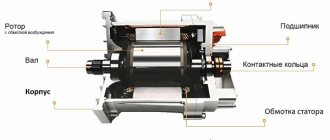
The rotor magnetic field, necessary to create the electromotive force of the stator winding of any generator, is created by direct current flowing through the field winding (OB) (see Fig. 3.1). The excitation system is designed to supply the OF, which largely determines the reliability of the operation of synchronous generators. In this regard, the following basic requirements are imposed on the excitation system:
- 1) reliable power supply with direct current OB in any modes, including during accidents in power systems;
- 2) stable regulation of the excitation current when the generator load changes;
- 3) required speed;
- 4) forcing excitation, i.e. ensuring a rapid increase in the excitation current, up to approximately double the value;
- 5) rapid damping of the excitation magnetic field during operational disconnections of the generator from the network.
Depending on the energy source used to power the OB, excitation systems are divided into groups:
- 1) electric machine excitation using a direct current generator;
- 2) electric machine excitation using an alternating current generator with the conversion of this current into direct current;
- 3) self-excitation by converting part of the alternating current electrical energy of the generator into direct excitation current energy.
Electric machine excitation systems, where the energy source is a direct current generator, i.e.
exciter have been used for a long time for most generators. Usually they were on the same shaft as the generator and were driven by the same turbine as the generator itself. Such a system is called direct. If the exciter is driven by a separate motor, the system is usually called indirect. In the domestic generator industry, as a rule, a direct excitation system is used, which has a lower cost and greater reliability. The increase in the power of turbo and hydrogen generators, and therefore the required power of exciters, initiated the need to replace DC generators with electric machine excitation systems using alternating current generators that do not have any power limitations. To convert alternating current into direct current, mercury rectifiers were previously used, which later gave way to controlled and uncontrolled semiconductor converters based on diodes, thyristors, and transistors. Semiconductor converters are more reliable, and in general the system with alternating current generators is faster, allowing for a high level of excitation (up to four times the rated excitation voltage with a time constant of the excitation system of less than two hundredths of a second). The widespread introduction of excitation systems with controlled converters was carried out for the first time in the world in our country. Subsequently, the transition to such systems was carried out abroad.
The power of the generators for the excitation system is 0.5-2% of the total power of the main generator. For example, for a 320 MW turbogenerator it reaches 2 MW, for 800 MW - 6 MW, etc., excitation currents - thousands of amperes (for powerful turbogenerators 5-8 thousand A). This circumstance creates great difficulties when organizing current supply to the excitation winding using sliding contact between the rotor slip rings and brushes. Therefore, a brushless excitation system has been successfully used for a number of generators, where direct current is supplied directly from the rotating exciter rotor to the excitation winding of the main generator. The alternating voltage of the field winding is converted into constant voltage by a rectifier bridge mounted on the rotor. Power rotary valves must have increased mechanical strength and vibration resistance.
The advantage of self-excitation systems is that they do not have an electric machine exciter - a generator. To power the main generator rotor winding, part of the main generator stator energy is used. As a result, the reliability of the system increases, its cost decreases, and the length of the generator is reduced. The initial excitation of the generator is carried out due to the residual magnetization of the machine or by current from an external source.
The excitation system includes an automatic excitation regulator (AEC). It maintains a given voltage level and ensures stability of the generator during voltage fluctuations in the electrical power system when the value and nature of the loads change, the power plant, power lines are turned off, or short circuits occur. The main requirements for AVR are speed of operation, stability of regulation, and provision of excitation boost during sudden drops in network voltage, which is fraught with loss of static and dynamic stability of generators.
The commissioning of long-distance power transmission lines, the integration of individual power systems into a single network, and the increase in generator capacity required a significant increase in their dynamic and static stability. Strong-action ARVs (ARV SD) were created that respond not only to deviations of the generator mode parameters (voltage, current, frequency), but also to the rate of their change.
If emergency conditions occur, short circuits in the generator, busbar or transformer, after a sudden shutdown of the generator, it is necessary to quickly reduce the magnetic field of the generator excitation winding. This operation is called field blanking and is carried out by a special field blanking machine (AGP). The AGP device is subject to two main, sometimes contradictory, requirements: the field suppression time should be as short as possible, and the induced overvoltage in the rotor winding that occurs during suppression should not exceed permissible values.
The main difference between this type of generator is that the magnetizing excitation winding is powered not from an external source, but from the generator itself. Therefore they are called self-excited generators.
Schematic diagram and design of the magnetic system of a four-pole self-excited generator.
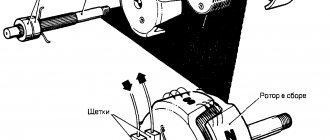
In collector generators, in addition to the main poles and windings, there are 2 additional poles, on which one turn of an additional series winding is placed. This is necessary to compensate for the magnetic flux of the armature reaction and maintain the position of the electrical neutral of the machine when the load changes.
For normal operation of a self-excited generator, it is necessary that the voltage supplied to the magnetizing winding does not change during the welding process, i.e. did not depend on the welding mode. For this purpose, a third additional brush z
, which is located between the two main brushes
a
and
b
.
When analyzing the operation of this generator, it is necessary to take into account the magnetic flux F i
created by the welding current flowing through the turns of the armature winding, the so-called armature reaction flux.
Picture of the distribution of magnetic fluxes under the polarity pole N
four-pole generator
It is clear from the figure that under one half of the poles the armature field lines enhance the magnetizing flux Fn.
and under the other, they weaken it. In general, the magnetizing effect of the armature reaction flux is compensated by its demagnetizing effect. Therefore, when analyzing the operation of generators with independent excitation, the influence of the armature reaction flux was not taken into account.
In self-excited generators, the parameters of the armature winding and the demagnetizing winding are selected so that under one half of the poles (between the brushes b - z
) the magnetic flux of the demagnetizing winding is compensated by the armature reaction flux. As a result, the voltage on the brushes bz will be determined by only half of the magnetic flux of the magnetizing winding.
Thus, the voltage supplying the magnetizing winding turns out to be independent of the welding current. The falling characteristic of the generator is ensured due to the demagnetizing effect of the demagnetizing winding, which manifests itself under the second half of the poles.
This allows us to conclude that the mode control in self-excited collector generators is the same. as in generators with independent excitation.
The peculiarity of self-excited generators is that they can only be started when the armature rotates in one direction, indicated by the arrow on the stator end cover.
This is due to the fact that the initial excitation of the generator when it starts is due to the residual magnetization of the poles. When the armature rotates in the opposite direction, a current in the opposite direction will flow in the excitation winding, which, with its growing magnetic field, at some point in time compensates for the residual magnetization of the poles, i.e. the total magnetic flux under the poles will become zero. In this case, to excite the generator, it is necessary to temporarily connect the magnetizing winding to an independent direct current source.
Unit ADD-303 with collector generator
VALVE WELDING GENERATORS
They appeared in the mid-70s of the 20th century after the development of the production of power silicon valves. In these generators, the function of current rectification, instead of a collector, is performed by a semiconductor rectifier, to which the alternating voltage of the generator is supplied.
Welding units use generators of three types of alternating current generator designs: inductor, synchronous and asynchronous
Alternator designs:
A -
inductor,
b -
synchronous,
c
- asynchronous
In Russia, welding units are produced with inductor generators with self-excitation, independent excitation and mixed excitation.
Scheme of a self-excited valve generator
Circuits of single-phase and three-phase valve generators with independent excitation
Constructive diagram and connection of parameters of an inductor generator
In an inductor generator, the stationary excitation winding is powered by direct current, but the magnetic flux it creates is variable. It is maximum when the teeth of the rotor and stator coincide, when the magnetic resistance along the flow path is minimal, and is minimal when the cavities of the rotor and stator coincide.
Hence. The emf induced by this flow is also variable. Three working windings are located on the stator with a shift of 120°, so a three-phase alternating voltage is formed at the generator output. The falling characteristic of the generator is obtained due to the high inductive reactance of the generator itself. The rheostat in the excitation circuit serves to smoothly regulate the welding current.
The absence of sliding contacts (between the brushes and the commutator) makes this generator more reliable in operation. In addition, it has a higher efficiency, smaller weight and dimensions than a collector generator. Dynamic characteristics can also be significantly improved.
Schematic diagram of a valve generator type GD-312 with self-excitation
VSKh generator GD-312
To ensure no-load operation, the excitation winding is powered from a voltage transformer, and to power it in short-circuit mode, from a current transformer. In load mode - welding - a mixed control signal proportional to part of the output voltage and proportional to the current is supplied to the excitation winding.
Valve generators are manufactured under the GD-312 brand and are used for manual welding of metals as part of ADB-type units
Connection diagrams for the windings of a three-phase inductor generator
Valve generator GD-4006
Schematic diagram of the generator GD-4006
VSKh generator GD-4006
In Russia, several designs of multi-station units are produced with the number of posts from 2 to 4.
The market offers universal units for several welding methods or welding and plasma cutting. In particular, the ADDU-4001PR unit
Design of the ADDU-4001PR unit
The formation of artificial VSCs of the ADDU-4001PR unit is ensured by a thyristor power unit with microprocessor control.
Wider technological capabilities are provided by the use of inverter power units in units, such as in the Vantage500 unit.
Inverter power supplies.
Inverting in converter technology is the conversion of direct voltage into alternating voltage.
Inverters of welding power sources are made using power thyristors and transistors. Thyristor inverters are inferior to transistor inverters in terms of maximum conversion frequency (by an order of magnitude) and, accordingly, in terms of weight and size indicators. Therefore, in the production of welding IP they are now almost completely replaced by transistor inverters.
Let's consider one of the widely used transistor inversion circuits.
Rectifier V1 converts the mains voltage (~380V, 50Hz) into constant voltage, the unevenness of which is smoothed out by filter L1—
C1
.
An inverter using transistors VT1-VT2 converts direct voltage into high-frequency alternating voltage (~ 50 kHz).
Next, the voltage (~ 380 V) is lowered by transformer T to welding voltage (80 V), rectified by rectifier V2 and smoothed by filter L2 -
C2. Since high-frequency alternating current is transformed, the transformer is made not with an iron core, but with a ferrite core, which reduces its weight by about 10 times. Since the frequency of the transformed current is high, the duration of transient processes is reduced from n*10 -2 s to 10 -3 s or less.
Currently, the bulk of inverter equipment for welding production consists of power supplies with high-frequency transformers, since electrical safety conditions during manual welding and semi-automatic hose welding, as well as during plasma cutting, require galvanic isolation of the secondary circuit from the power network.
Regulating the mode (obtaining a falling current-voltage characteristic and adjusting the secondary voltage on the hard characteristic) is usually carried out by changing the frequency.
Oscillograms when regulating voltage by changing amplitude (a), frequency (b)
and pulse width (in)
To obtain a falling characteristic, current feedback is introduced: as it increases, the frequency automatically decreases, which entails a decrease in the output voltage. To stabilize the output voltage at rigid characteristics, voltage feedback is introduced.
External characteristics of rectifiers with inverter
In the 80s and until the mid-90s, inverter rectifiers were produced with low power (up to 160 A), for installation work and for domestic needs. In the mid-90s, a new generation of so-called field-effect transistors appeared that could withstand high currents. This made it possible to begin producing industrial inverters for currents of 300-500 A.
Modern switching devices: MOS transistor (a); bipolar transistor with insulated gate (b);
transistor-diode module - chopper
(c);
power module with optimized control and comprehensive internal protection
(d)
Welding power supplies with power transistors use several inversion circuits.
Single-ended converter with direct diode connection
Single-ended converter with reverse diode connection
Push-pull bridge converter
Push-pull half-bridge converter
Resonant push-pull bridge converter
Real power circuits of inverter power supplies may differ significantly from standard ones.
Rectifier DS.250.33
Straightener Caddy Arc 150
Rectifier InvertecV350-PRO
Rectifier Forsazh-160
Generator excitation systems can be divided into groups:
1) independent excitation, i.e. electric machine exciters of direct and alternating current coupled to the generator shaft;
2) self-excitation (dependent excitation), i.e. excitation systems receiving power directly from the generator terminals through special step-down transformers.
Independent excitation of generators (the main advantage is that the excitation of the SG does not depend on the mode of the electrical network and is therefore the most reliable) is the most common.
Disadvantages: relatively low rate of increase in excitation (determined mainly by the lack of the exciter);
decreased reliability of the DC generator due to vibration and difficult operating conditions of the commutator brushes (for turbogenerators with high rotation speeds).
Self-excitation systems, in general, are less reliable than independent excitation systems, since in them... the operation of the exciter depends on the mode of the alternating current network.
Circuit of independent electric machine excitation (left), circuit of dependent electric machine excitation, i.e., self-excitation (right).
On the diagram; OVV(G) — excitation winding of the exciter (generator); ShR - shunt rheostat; B - pathogen; IM-asynchronous.motor; M - flywheel; SG - synchronous generator; MV buses for own needs.
A promising system, especially for high-power turbogenerators, is a brushless excitation system in which there are no moving contact connections.
To create the main magnetic flux of the generator, an excitation winding with direct current is made. When the excitation current changes, the generator voltage and the reactive power supplied from the network change. Excitation system parameters: voltage rise release and boost ratio. Excitation systems are divided into independent excitation and self-excitation.
Independent electric machine excitation system
.
Regulation of the exciter voltage and, consequently, the excitation current of the main generator is carried out by changing the current in the excitation winding of the exciter. Advantages: does not depend on the network mode. Disadvantage: at high rotation speeds, the influence of commutation, a large reactive emf, leads to breakdown of the insulation of the collector plates and failure of the collector. High frequency excitation system
. It consists of an exciter, which is a high-frequency generator, with three excitation windings, frequency 500 Hz. The first excitation winding is connected in series with the excitation winding of the main generator. The other two are powered by a sub-exciter generator with a frequency of 400 Hz (multipole), with permanent magnets and windings connected in an open delta. The exciter and sub-exciter are on the same shaft with the generator. The current in the other two windings of the subexciter is regulated by the ARV (maintaining voltage in normal mode) and UBF (non-contact forcing device) blocks connected to the current and voltage transformer at the generator terminals. Force ratio 2, voltage rise rate less than 2 1/s.
Thyristor excitation system
. The exciter is a three-phase machine with windings connected in a star. Its excitation winding is powered from a rectifier transformer, through a rectifier. The excitation winding of the main generator is connected through 2 groups of thyristor rectifiers: working VS1, and forcing VS. When boosting, the operating thyristors are closed by a higher voltage at VS2.
Brushless system
. Conductors connecting the field winding to the exciter with conductors on the shaft through a rotating rectifier. Eliminates the need for brushes and slip rings.
Electric machine self-excitation system. The exciter is rotated by a motor connected to the unit's auxiliary transformer.
Thyristor self-excitation system
. The generator winding is connected to thyristor rectifiers receiving power from the TSN unit. They consist of controllable ones, regulating the voltage in normal mode, and uncontrollable ones, when boosting.
The rotor winding of a synchronous generator is powered by direct current, which creates a magnetic excitation flux. The rotor winding, direct current source, control and switching devices make up the generator excitation system.
Excitation systems must:
· ensure reliable power supply to the rotor winding in normal and emergency modes;
· allow regulation of the excitation voltage within sufficient limits;
· provide fast-acting excitation control with high forcing ratios in emergency modes;
· carry out rapid de-excitation and, if necessary, extinguish the field in emergency modes.
The most important characteristics of excitation systems are: speed, determined by the rate of voltage rise on the rotor winding during boost
V
=0.632(
U f
sweat –
U f
nom)/
U f
nom
t
1
and ratio of ceiling voltage to rated excitation voltage
Uf
sweat
/ U f
nom
= k
f
the so-called boost ratio.
According to GOST, turbogenerators must have k
f
>2,
and the rate of increase in excitation is not less than 2 s -1. The boost factor for hydrogen generators must be at least 1.8 for collector exciters connected to the generator shaft, and at least 2 for other excitation systems. The rate of rise of the excitation voltage must be at least 1.3 s -1 for hydro generators with a power of up to 4 MB A inclusive and at least 1.5 s -1 for hydro generators of high power.
For powerful hydrogen generators operating for long-distance power transmission, higher requirements are placed on excitation systems: k
f
=
3 – 4, excitation growth rate up to 10
U f
nom per second.
The rotor winding and excitation systems of generators with indirect cooling must withstand twice the rated current for 50 s. For generators with direct cooling of the rotor windings, this time is reduced to 20 s; for generators with a power of 800–1000 MW, the time is 15 s, 1200 MW - 10 s (GOST 533-85E).
Depending on the power source, excitation systems are divided into systems of independent excitation and self-excitation.
In an independent excitation system, an exciter is located on the same shaft as the generator - a direct or alternating current generator. In a self-excitation system, the excitation winding is powered from the generator terminals through special step-down transformers and rectifiers.
GE DC generator is used as an exciter
connected to the generator shaft (Fig. 2.9,
a
)
.
The excitation winding of the exciter
LGE
is powered from the exciter armature, the current in it is regulated by a rheostat
RR
or an automatic excitation regulator ARV.
The current supplied to the excitation winding LG
of the synchronous generator
G
is determined by the voltage across the exciter.
GE
DC generator due to vibration and difficult switching conditions at a high rotation speed of 3000 rpm.
Another disadvantage is the low rate of increase in excitation, especially for hydrogen generators ( V
= 1–2 s -1).
Rice. 2.9. Schematic diagrams for excitation of generators:
A -
independent electric machine excitation;
b
– semiconductor self-excitation
In the self-excitation system (Fig. 2.9, b
)the excitation winding of the
LG
receives power from the
TE
connected to the generator terminals, through the ACV-controlled valves
VS
and from the current transformers
TA
through the uncontrolled valves
VD.
The current of the
VD
is proportional to the stator current, so they provide forced excitation and operation of the generator under load.
Controlled VS
supply a current proportional to the generator voltage and provide normal voltage regulation. This system is used for powerful synchronous machines.
An excitation system with a 50 Hz machine exciter and static rectifiers (static thyristor system of independent excitation - Fig. 2.10) has become widespread. On the same shaft with generator G
there is an auxiliary synchronous generator
GE,
which has a three-phase winding on the stator with taps, to which two groups of thyristors are connected: working group
VD1 -
for low exciter voltage and forcing group
VD2 -
for full voltage.
The use of two groups of thyristors provides an excitation ceiling of up to 4 U f
nom and high speed (
V
= 50 s 1). Both groups are connected in parallel using a three-phase bridge circuit. In Fig. To make the circuit easier to read, Fig. 2.10 shows thyristors in only one phase.
Thyristor control system AVD2
and
AVD1
is powered by transformer
TA1
and is connected to AVR (automatic excitation control).
The exciter GE
has an excitation winding
LGE,
which receives power from transformer
TA2
through valves
VD.
The considered diagram also shows the elements of the automatic magnetic field suppression (AGC) circuit: AGC machine, resistor
R,
spark gap
FVn,
contactor
KM.
Rice. 2.10. Static thyristor system of independent excitation
Rice. 2.11. Brushless excitation system
The disadvantages of the circuit include the presence of an alternating current exciter, which complicates operation, as well as the presence of sliding contacts between fixed brushes, to which a system of fixed thyristors is attached, and movable contact rings of the CC rotating on the rotor shaft.
The latter drawback led to the development of a brushless excitation system (Fig. 2.11). As a causative agent of GE
This system uses a 50 Hz synchronous generator, the field winding
LE
is located on a stationary stator, and the three-phase winding is located on a rotating rotor.
LE
winding receives power from the
GEA
via the
VDE rectifier.
On the same shaft with the exciter, VD thyristors are mounted on special disks,
which rectify the alternating current of the exciter and supply it to the generator rotor along rigid tires without rings and brushes, since the generator rotor,
VD
and the exciter rotor rotate on the same shaft at the same speed.
The excitation current is regulated from the ARV by influencing the thyristors through a pulse device L
and a rotating transformer
TA.
The advantage of this system is the absence of slip rings and brushes, the disadvantage is the need to stop the generator to switch to backup excitation or to replace thyristors.
The brushless system is used for synchronous compensators with a power of 50 MB-A or more and turbogenerators with a power of 800 MW or more.
For turbogenerators, excitation is an integral part, and the reliable and stable operation of the entire turbogenerator largely depends on the reliability of its operation.
The excitation winding is placed in the slots of the generator rotor, and direct current from the source is supplied to it using slip rings and brushes, with the exception of a brushless excitation system. A direct or alternating current generator, which is usually called an exciter, can be used as an energy source, and the excitation system can be an electric machine. In a machineless excitation system, the source of energy is the generator itself, which is why it is called a self-excitation system.
The main excitation systems should:
Provide reliable power to the rotor winding in normal and emergency modes;
Allow regulation of the excitation voltage within sufficient limits;
Provide fast-acting excitation control with high forcing ratios in emergency modes;
Carry out rapid de-excitation and, if necessary, extinguish the field in emergency modes.
The most important characteristics of excitation systems are: speed, determined by the rate of voltage rise on the rotor winding when forcing V
=0.632∙
(U f
sweat -
U f
nom
)/U f
nom ∙
t 1,
and the ratio of the ceiling voltage to the rated excitation voltage
U f
sweat /
U f
nom =
K
f - the so-called boost ratio.
According to GOST, turbogenerators must have K
f ≥2, and the rate of increase in excitation is at least 2 s -1. The boost factor for hydrogen generators must be at least 1.8 for collector exciters connected to the generator shaft, and at least 2 for other excitation systems. The rate of rise of the excitation voltage must be no less than 1.3 s -1 for hydro generators with a power of up to 4 MBA inclusive and no less than 1.5 s -1 for hydro generators of high power.
For powerful hydrogen generators operating for long-distance power transmission, higher requirements are placed on excitation systems :
f =3-4, excitation growth rate up to 10∙
U f
H 0 M per second.
The rotor winding and excitation systems of generators with indirect cooling must withstand twice the rated current for 50 s. For generators with direct cooling of the rotor windings, this time is reduced to 20 s; for generators with a capacity of 800-1000 MW, the time is 15 s, 1200 MW - 10 s (GOST 533-85E).
The power of the excitation source is usually 0.5 - 2% of the power of the turbogenerator, and the excitation voltage is 115-575 V.
The greater the power of the turbogenerator, the higher the voltage and the lower the relative power of the exciter.
Excitation systems can be divided into two types: independent (direct) excitation and dependent (indirect) excitation (self-excitation).
The first type includes all electric machine exciters of direct and alternating current, coupled to the shaft of the turbogenerator (Fig. 4.1).
The second type includes excitation systems that receive power directly from the generator terminals through special step-down transformers (Fig. 4.2, a
) and separately installed electric machine exciters, rotated by AC motors powered by the station’s own buses (Fig. 4.2,
b
).
DC electric machine exciters (Fig. 4.1, a
) were previously used on low-power turbogenerators. Currently, such an excitation system is practically not used, since it is low-power and at a rotation speed of 3000 rpm, this excitation system is difficult to implement due to the difficult operating conditions of the commutator and brush apparatus (deterioration of switching conditions).
On existing turbogenerators the following is used:
High frequency excitation system;
Brushless excitation system;
Static thyristor independent excitation system;
Static thyristor self-excitation system.
In the listed excitation systems, the exciter is an alternating current generator of various designs, which has no power limitation. To convert alternating current into direct current, uncontrolled and controlled semiconductor rectifier valves are used.
Operating principle of high-frequency excitation (Fig. 4.1, b
) is that a high-frequency three-phase current generator of 500 Hz rotates on the same shaft with the generator, which through semiconductor rectifiers B supplies rectified current to the rotor rings of the turbogenerator. With such an excitation system, the influence of changes in operating modes of the external network on the excitation of the generator is eliminated, which increases its stability during short circuits in the power system.
Rice. 4.1. Schematic diagrams of an independent generator excitation system:
A
— electric machine with a direct current generator;
b
- high frequency;
SG
— synchronous generator;
VG
- direct current exciter;
VCHG
— high-frequency generator;
PV
- sub-exciter;
B
- rectifier
Rice. 4.2. Schematic diagrams of a dependent generator excitation system;
VT
— auxiliary transformer;
AD
- asynchronous motor
On modern turbogenerators, the high-frequency excitation system is not used, as it is outdated. For powerful turbogenerators, excitation currents are 5-8 kA. This creates great difficulties in supplying direct current to the excitation winding of the generator using sliding contacts - rings and brushes. Therefore, a number of generators currently use a brushless excitation system, in which the rectifier device is located on the rotor and is powered by a reversible machine through an air gap. Therefore, the electrical connection between the rectifier and the excitation winding is made by a rigid current conductor without the use of slip rings and brushes.
In an independent static system and a self-excitation system, controlled semiconductor silicon rectifiers - thyristors - are used. This made it possible to increase the speed of these excitation systems compared to a system, for example, a high-frequency one, where uncontrolled rectifiers are used. Since these excitation systems use a group of static controlled rectifiers, sliding contacts are also used to supply direct current to the generator excitation winding, which is a disadvantage. Thyristor excitation systems have found application for turbogenerators with a capacity of 160-500 MW. In Fig. 4.2, a
A schematic diagram of static thyristor self-excitation is shown.
In case of damage to the excitation system, provision is made for the installation of backup exciters: one for every four generators.
As a backup exciter, DC generators are installed, driven by asynchronous motors connected to the station’s own buses (Fig. 4.2, b
). So that when the voltage drops, for example during a short circuit, the backup exciter does not slow down, a flywheel is installed on its shaft.
Brushless diode systems (BDS)
Brushless diode systems (BBD) are designed to power the excitation winding of turbogenerators with rectified controlled current - Fig. 5.4a, b. The brushless exciter is a synchronous generator of reverse design, the armature of which with an alternating current winding and a diode rectifier is rigidly connected to the rotor of the excited turbogenerator. The excitation winding of the exciter is located on its stator.
The main advantage of brushless exciters is the absence of slip rings and brush contact in the turbine generator rotor winding circuit and the reduction in machine length.
Abrahamyan Evgeniy Pavlovich
Associate Professor, Department of Electrical Engineering, St. Petersburg State Polytechnic University
This makes it possible to provide excitation of heavy-duty machines, the excitation currents of which exceed 5500A, characteristic of the STN system - Fig. 5.2. The rectified rated voltage is up to 600V, and the rectified rated current is up to 7800A. The cooling system of the rotating diode rectifier is natural air.
Regulation of the generator excitation is carried out by controlling the current of the excitation winding of the reversed exciter. A typical system set includes an automatic field suppression device, a thyristor arrester and two conversion-regulating channels (AVR-1, AVR-2) of automatic excitation regulators of the main and reserve channels, respectively. One of the channels (AVR-1) is in active mode, the other (AVR-2) is in hot standby. In a particular case, the main control channel receives power from a rectifier transformer connected to the generator busbar, and the backup channel receives power through a rectifier transformer from the power plant’s auxiliary busbars.
Fig.5.5. Brushless diode system (BBD) with thyristor excitation (TV-1, TV-2) of the exciter winding (OVW). SG – synchronous generator; OVG – generator excitation winding; DSV – diode synchronous exciter; DV – rotating diode rectifier; B – inverted synchronous exciter and its excitation winding OVV; TV-1, TV-2 – thyristor rectifiers of the first and second channels for powering the air supply; VT-1, VT-2 – rectifier transformers of the first and second channels; ARV-1, ARV-2 – automatic excitation regulators of the first and second channels; P1, P2, P3, P4 – disconnectors; TT1, TT2, TN1, TN2 – measuring current and voltage transformers of the first and second channels; TA11, TA12 – exciter excitation current sensors; AGP – automatic field extinguishing device; TR – thyristor discharger.
Fig.5.6. Brushless diode (BBD) excitation system for a diesel generator. SG – synchronous diesel generator; OVG – excitation winding; DV – diode rectifier; T – thyristor; ARV – automatic excitation regulator; ITT, ITN – current and voltage measuring transformers; TST with MSh is a three-winding summing transformer with a magnetic shunt.
The brushless diode excitation system (BDS) has a lower operating speed compared to thyristor systems (STS and STN). Thus, the time for the rise of the excitation voltage to the maximum value when the positive sequence voltage at the control point decreases by 5% of the nominal value is no more than 50 ms, whereas in thyristor systems it is no more than 25 ms.
In the circuit in Fig. 5.4a, the excitation winding of the diode exciter is powered from a magnetoelectric subexciter with permanent magnets, and in the circuit in Fig. 5.4b - from a rectifier transformer connected to the generator current lead of the excited machine. In both cases, a thyristor rectifier controlled by the ARC system is used to power the excitation winding (OVW) of the reversed exciter (B).
Fig.5.7. Brushless diode (BBD) excitation system for a diesel generator. SG – synchronous generator; OVG – generator excitation winding; DSV – diode synchronous exciter; DV – rotating diode rectifier; B – reversed synchronous exciter; OVV – exciter excitation winding; PV – magnetoelectric subexciter with permanent magnets; ARV – automatic excitation regulator; TV – thyristor rectifier for power supply of OVV.
As one of the modern variants of the circuit in Fig. 5.4b with a rectifier transformer (VT), Fig. 5.5 shows a brushless diode system (BDS) with thyristor power supply via two channels (from the MV network through VT-2 and from the generator conductor through VT-1) exciter excitation windings (ECW).
How does he work
First, let's figure out how this device functions. His work scheme is as follows:
- The key is inserted into the ignition switch;
- The current goes to the excitation wires;
- The magnetic field created by the armature passes through the stator windings, and voltage appears at its terminals;
- When the armature rotation frequency becomes high enough, the self-excitation mode begins;
- The rectifier unit provided by the car design converts alternating current into direct current;
- The voltage regulator starts working when the crankshaft rotation speed changes, and the time for which the excitation wire is activated is adjusted.
The presented video will allow you to clearly get acquainted with the principle of operation of the generator.
Beginners are very interested in the most important question, without which there is no point in trying to fix something on their own - what is the generator used for.
First of all, the generator’s task is to provide energy to all electrically dependent equipment.
The mistake many people make is that the equipment is powered by a battery. The battery is needed to maintain the functionality of the devices when the engine is turned off. It powers the audio system, alarm system, etc.
When the engine is started with the help of the battery, all the reins of power pass to the generator. He is now responsible for the operation of the audio system, air conditioning, power windows, etc.
The second, but no less important task of the battery is to recharge the battery. This happens when the engine is running. If it were not for the generator, the battery would not be able to provide power to all consumers for a long time; it would have to be charged regularly in the garage.
Excitation systems for diesel generators
JSC "Electrosila" is a manufacturer of diesel generators with a capacity from 200 to 6300 kW with a wide range of voltages and speeds. Two types of excitation systems are manufactured for diesel generators: by compounding, implemented on the basis of a three-winding summing transformer with a magnetic shunt and a controlled thyristor-diode converter is shown in Fig. 5.6. The power part is made in the form of a unit with forced cooling and is located on the generator housing. A small-sized voltage regulator is installed in the control panel of the power unit.
A brushless system with a diode synchronous exciter (SBD), a magnetoelectric subexciter with permanent magnets and a static thyristor excitation regulator is shown in Fig. 5.7.
The rotating part of the system equipment (diesel generator, diode synchronous exciter and magnetoelectric sub-exciter) is manufactured in the form of a compact unit mounted on the generator shaft due to the combination of the design.
The excitation regulator is located in a separate cabinet. The main characteristics of diesel generator excitation systems are presented in Table 5.1.
Table 5.1. Main characteristics of excitation systems for diesel generators. The excitation systems of diesel generators are characterized by complete autonomy - the initial excitation is provided exclusively by internal sources.
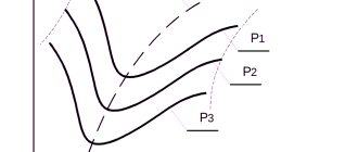
Simple electromagnet and field concentration
If the rotor coil is wound with a non-iron core as shown in Fig. 3.13(a) , then you get a magnet with one pair of poles N ( North - northern) and S ( South - southern).
Rice.
3.13(a). A simple electromagnet. Due to the large distance between the poles, the magnetic field lines will be highly scattered in space. Now let's stretch the poles of the magnet towards each other, so that there is only a small gap between them (see Fig. 3.13 ( b )).
Rice. 3.13(6). Let's bend the ends of the electromagnet to concentrate the field.
And finally, let's make the poles of the magnet in the form of a set of teeth that fit into each other, but without touching (see Fig. 3.14 ). We will get in total a long narrow gap between the poles N and S , through which the magnetic field will “leak” outward. When the rotor rotates, this “leakage” will cross the stator windings and induce an emf in them.
Automatic field extinguishing machines (AGP)
Field damping machines are designed for switching the excitation winding circuits of turbo and hydrogen generators that have slip rings on the rotor, as well as for field damping of these machines.
Optimal conditions for intensively reducing the rotor current to zero are provided by discharging the excitation winding onto a nonlinear resistor, the resistance of which varies in inverse proportion to the current value.
Thanks to the special design of the ring arc extinguishing grid of the field extinguishing machine, the arc burning in it has the current-voltage characteristic of a nonlinear resistor, which ensures minimal field extinguishing time and a safe voltage level on the rotor rings. The main characteristics of the AGP produced by Elektrosila JSC are presented in Table 5.2.
Basic information about the excitation effect
ATTENTION! A completely simple way to reduce fuel consumption has been found! Don't believe me? An auto mechanic with 15 years of experience also didn’t believe it until he tried it. And now he saves 35,000 rubles a year on gasoline! Read more". As is known, the voltage generated by the gene at different engine speeds is regulated by excitation windings
The current is maintained at a constant voltage – 13.8-14.2 V
As is known, the voltage generated by the gene at different engine speeds is regulated by excitation windings. The current is maintained at a constant voltage - 13.8-14.2 V.
Purpose and device
Modern alternators work on the same principle, but use different mechanisms as the driving force. The main purpose of an alternator is to convert some type of energy into electrical current. The energy source can be:
- Powerful flow of water. Such devices are used in hydroelectric power plants. The generator is driven by the flow of water through a narrow channel and the rotation of a turbine. The rotating turbine blades spin the generator shaft, thereby converting mechanical energy into electricity.
- Gas burning. Typical for thermal power plants.
- Using the power of the wind. Such generators are installed in the most windy areas. The main disadvantage is the complete shutdown in calm weather.
- Use of nuclear energy.
- The use of diesel or gasoline engines to rotate stationary or automobile generators.
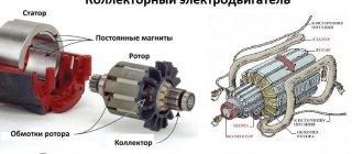
An alternator or alternator consists of the following parts:
- Stator. It is a stationary part of the device. Made from steel sheets that provide resistance to loads. The stator has long slots cut into it to contain the wire winding. This winding removes the generated current.
- Rotor. It is a moving part. Installed directly in the center of the stator. For precise alignment, it is mounted on bearings that are mounted in the front and back covers of the housing. The rotor itself is an electromagnet. It also has grooves and a winding laid in them. It is necessary to excite the stator and generate an electromagnetic field.
- Anchor. A rotor with a winding is mounted on it. It is needed to transmit torque from an engine or turbine.
- Collector. The collector consists of several insulated plates, which are represented by 2 main half rings. Each is connected to the rotor winding. One half with the “+” pole, the other with the minus pole. The generator commutator is needed to rectify and redirect the alternating current.
- Carbon brushes. On some models they are replaced with contact plates. Through the carbon brushes, direct current is supplied from the battery, which is used to pre-excite the rotor winding.
These are the most basic parts that make up the simplest alternator. We examined the design and principle of operation of a modern alternating current generator.
Generators of this type can be synchronous or asynchronous. Both devices are almost identical. The difference between them is as follows. Synchronous and asynchronous models differ in the presence of a winding on the rotor (synchronous) or its absence (asynchronous). The differences also lie in the excitation principle and connection diagram.
Connection diagram for the VAZ-2108 generator
The VAZ-2108 generator has a rather massive stator winding, since it uses a large cross-section wire. It is with its help that electricity is generated. The wire is wound evenly over the entire inner surface of the stator into recesses specially provided for this purpose in the magnetic core. It’s worth talking about the latter separately. The middle part, the generator stator, consists of a series of thin metal plates pressed tightly together. They are often boiled on the outside to prevent separation.
Alternator faults
The following main malfunctions may occur in generators:
- poor contact between brushes and rotor slip rings
- open field winding
- short circuit of the excitation winding to the rotor body
- turn-to-turn short circuit in the field winding coil
- break in the stator phase winding circuit
- interturn short circuit in the stator winding coils
- short circuit of the stator winding to the housing
- shorting the “plus” clamp to the body
- breakdown of rectifier block diodes
- mechanical problems
Poor contact between brushes and rotor slip rings
Poor contact between the brushes and the rotor slip rings occurs when the slip rings are dirty and oily, the brushes are worn out, the spring pressure on the brushes decreases, and the brushes get stuck in the brush holders. With such defects, the resistance in the excitation circuit increases (or even the excitation circuit is interrupted), which causes a decrease in the strength of the excitation current, and the power of the generator decreases.
To eliminate the malfunction, remove the brush holder and check its condition. If necessary, wipe the brush holder and brushes with a rag moistened with gasoline. Brushes must move freely in the brush holders. When the brushes are worn to a height of 8 mm, they are replaced, followed by checking the spring pressure on each brush separately.
Contaminated rotor slip rings are wiped with a rag moistened with gasoline. The oxidized working surface of the rings is cleaned with glass sandpaper.
Open field winding
Breakage of the excitation winding most often occurs in places where the ends of the winding are soldered to the slip rings.
When the field winding breaks, an EMF of no more than 5 V is induced in the stator winding, due to the residual magnetism of the rotor steel. If this malfunction occurs, the battery will not charge. To determine the break, it is necessary to disconnect the end of the field winding from the brush, and then connect the wires from the battery to this end and to terminal Ш of the generator through a lamp or voltmeter.
If the winding is broken, the lamp will not light up and the voltmeter needle will not deviate. To find a coil with a broken winding, wires from the battery terminals are connected to the ends of each coil. After this, carefully check the soldering joints and the output ends of the field winding coils. The discovered break point is eliminated by acid soldering using soft solders. When a break occurs inside the coil, it is replaced or rewound.
Turn-to-turn short circuit in field winding coils
An interturn short circuit in the excitation winding coils occurs due to the destruction of the winding wire insulation due to overheating or mechanical damage, which causes an increase in the excitation current and an increase in the temperature of the winding.
To determine the turn short circuit in the coils, measure their resistance with an ohmmeter and compare it with the resistance of a working coil.
Short circuit of the field winding to the rotor body
When there is a short circuit to the frame, part or all of the excitation winding is short-circuited, as a result of which the generator is not excited. Most often, the winding is closed to the housing at the points where its ends lead to the rotor slip rings. A short circuit of the winding to the housing causes an increase in current in the voltage regulator circuit.
This type of damage is determined by a 220 V test lamp. One wire is connected to any slip ring, and the other to the rotor core or shaft. The lamp will light when the winding is shorted to the housing. If it is impossible to isolate the winding from the housing, then it is replaced.
Short circuit of the stator winding to the housing
A short circuit of the stator winding to the housing occurs due to mechanical or thermal damage to the winding insulation. With this malfunction, the power of the generator is significantly reduced. The generator is overheating. The battery is charged only at increased engine speed.
This type of damage is determined with a 220 V test lamp by connecting one probe to the core and the other to any terminal of the winding. The lamp lights up only when the winding is short-circuited to the housing. Defective coils are replaced.
Closing the positive terminal of the generator to the housing
The short circuit of the generator plus terminal to the housing occurs due to the destruction of the terminal insulation or the insulation of the wire connected to this terminal.
With such a malfunction of the generator, the current in the stator winding and in the diodes of the rectifier unit sharply increases, which leads to thermal destruction of the winding insulation and breakdown of the diodes of the rectifier unit.
After the breakdown of the diodes, a short circuit of the battery occurs, as a result of which the battery is deeply discharged and the insulation of the connecting wires is destroyed, and the ammeter also fails.
The defective clamp insulation is restored. Damaged stator windings and a diode rectifier unit are replaced with serviceable ones in a repair shop.
Interturn short circuit in the stator winding coils
An interturn short circuit in the stator winding coils occurs when overheating occurs due to the destruction of the winding insulation. Short-circuited coils carry a lot of current, which causes the coil to overheat and causes further destruction of the winding insulation.
With such a malfunction, the power of the generator is significantly reduced, and the battery is charged only at high engine speeds.
Breakdown of rectifier diodes
Breakdown of the rectifier diodes occurs when overheating by high current, the generator voltage increases above normal, and due to mechanical damage.
In broken diodes, the resistance is practically zero in both directions, which causes a short circuit in the stator winding phases and generator failure.
When the diodes breakdown, the battery begins to discharge through the stator winding, which causes destruction of the winding insulation and rapid discharge of the battery.