The voltage limiter (hereinafter referred to as surge arrester - nonlinear voltage limiter) is a critical device. Accordingly, it is in itself a source of potential danger, and simply breakdown and failure are not the most serious consequences of improper operation.
The arrester must be checked periodically, and testing of non-linear voltage limiters is a strict procedure that must be carried out in accordance with GOST.
The most common surge arresters are designed for 0.4, 6, 10, 35 and 100 kV, and due to the wide range of voltage values, different testing methods are used for them. Regulatory documents are constantly verified with international analogues, so in our case we can be guided by the international standard IEC 60099-4:2004 and GOST R 52725-2007 developed on its basis.
Different manufacturers make their own additional adjustments, but only in terms of voltage and current threshold values. The methods themselves are quite simple and are unambiguously described in the Electrical Installation Rules (PUE) in paragraph 1.8.31.
Introductory part.
- This Methodology No. 15 “Testing valve-type arresters and surge arresters up to 10 kV” (hereinafter referred to as the Methodology) is intended for measuring the parameters of arresters and surge suppressors in order to determine the compliance of these parameters with the requirements of the PUE 7th ed., Chapter 1.8.31. and PTEEP Appendix 3, Table 17.
- According to the normative and technical documentation, arresters are tested to the following extent;
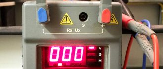
- Measurement of arrester resistance.
- Measurement of conduction current of valve-type arresters at rectified voltage.
- This methodology uses terms and definitions in accordance with the PUE and the set of standards GOST R 50571.16-2007.
Insulation resistance is the ratio of the voltage applied to a dielectric to the current flowing through it (leakage current).
High-voltage testing - supplying high voltage from an external source.
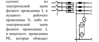
An electrical circuit is a set of electrical equipment connected by wires and cables through which electric current can flow.
Current-carrying part is an electrically conductive part of an electrical installation that is under operating voltage during its operation.
Standards of measurement error.
- This technique is intended to calculate the maximum possible value of measurement error, taking into account all factors influencing measurement errors.
- Before taking measurements you must:
- reduce the number of factors causing additional error;
- install the device almost horizontally: the deviation from the horizontal position should be within +3°, away from powerful sources of electromagnetic (magnetic) radiation (noise);
- perform reliable connection of electrical connection elements.
- carrying out work under normal environmental conditions. Normal conditions of use, limits of the main error value and limits of permissible values of additional errors under the influence of external influencing factors are given in the passport of measuring instruments and testing equipment.
- Measurements of electrical quantities are made by analogue (pointer) and digital measuring instruments, each of which has a measurement error.
- To obtain reliable measurement results, these errors must be taken into account.
- The relative measurement error in the general case is determined by the formula:
where: – the main reduced relative instrumental error, determined by the accuracy class of the device,
– relative measurement error caused by the i-th external factor that reduces the measurement accuracy (temperature, instrument position, viewing angle to the scale plane and other methodological errors). It is difficult in practice to take into account all the values of relative errors caused by all external factors. Based on this, the relative instrumental error of the device and the main errors caused by the measurement conditions are taken into account
Where:
here is the accuracy class for £
Apr – measurement limit (scale length) of the device:
Aism – instrument readings in units of measurement (scale length);
δns – error due to instability of instrument readings in steady state;
- Based on the operating principle of some devices, their main reduced instrumental error is determined by the formula:
where: Aism – instrument readings,
Apr is the measurement limit of the device,
k – coefficient of dependence of the magnitude of the main error on the instrument readings.
- For some instruments, the value does not depend on the instrument readings and is fixed over the entire measurement range. This is also indicated in the device datasheet.
- Formula (2) allows us to estimate the measurement error with a sufficient degree of accuracy, subject to strict adherence to the following rules for working with electrical measuring instruments:
- When carrying out measurements, analog instruments must be placed on a horizontal rigid base (with the exception of instruments with a vertical working position);
- when using multi-limit instruments, select measurement limits that are as close as possible to the values of the measured quantities; select one-limit instruments according to the same principle;
- determine instrument readings at a viewing angle of 90° to the scale plane (when using instruments with a mirror scale, the instrument needle must be aligned with its reflection);
- do not place measuring instruments on surfaces and bases subject to vibrations and vibrations
- in the absence of hard surfaces and bases, holding the device in your hands, give it a horizontal position, take measurements only after aligning the device needle with the zero mark of the scale. When using digital instruments, the measurement error is determined by the expression:
where: is the constant component of the relative error over the entire measurement range, n is the number of units of resolution of the device.
Tubular arresters
Checking the condition of the arrester surface
The outer surface of the arrester should not have electric arc burns, cracks, delaminations and scratches with a depth of more than 0.5 mm over a length of more than a third of the distance between the tips.
Measuring the surface electrical resistance of a fiber-bakelite arrester
The check is carried out before installing the arrester with a megohmmeter for a voltage of 2500 V. The surface electrical resistance must be at least 10,000 MOhm.
Measuring the diameter of the arc-extinguishing channel of the arrester
The channel diameter must correspond to the data given in table. 5
P, M. Measurement of the internal spark gap of the arrester
When commissioning, the dimensions of the internal spark gap must correspond to the data given in table. 22.1. During overhaul tests, these dimensions should not exceed the values indicated in table. 22.1 for arresters RTF 6-10 kV - by 3 mm, RTF-35 - by 5 mm, RTV 6-10 kV - by 8 mm, RTV 20-35 kV - by 10 mm, RTV-110 - by 2 mm.
P, M. Measurement of the external spark gap of the arrester
The dimensions of the external spark gap must correspond to the data given in table. 5
Table 5
| Technical data of tube arresters | |||||||
| Arrester type | Rated voltage, kV | Shutdown current, kA | External spark gap, mm | Initial diameter of the arc extinguishing channel, mm | Final diameter of the arc extinguishing channel, mm | Initial length of the internal spark gap, mm | Final length of the internal spark gap, mm |
| RTF-6 | 6 | 0,5-10 | 20 | 10 | 14 | 150±2 | – |
| RTV-6 | 6 | 0,5-2,5 | 10 | 6 | 9 | 60 | 68 |
| 2-10 | 10 | 10 | 14 | 60 | 68 | ||
| RTF-10 | 10 | 0,5-5 | 25 | 10 | 11,5 | 150±2 | – |
| 0,2-1 | 25 | 10 | 13,7 | 225±2 | – | ||
| RTV-10 | 10 | 0,5-2,5 | 20 | 6 | 9 | 60 | 68 |
| 2-10 | 15 | 10 | 14 | 60 | 68 | ||
| RTF-35 | 35 | 0,5-2,5 | 130 | 10 | 12,6 | 250±2 | – |
| 1-5 | 130 | 10 | 15,7 | 200±2 | – | ||
| 2-10 | 130 | 16 | 20,4 | 220±2 | – | ||
| RTV-35 | 35 | 2-10 | 100 | 10 | 16 | 140 | 150 |
| RTV-20 | 20 | 2-10 | 40 | 10 | 14 | 100 | 110 |
| RTV-110 | 110 | 0,5-2,5 | 450 | 12 | 18 | 450±2 | – |
| 1-5 | 450 | 20 | 25 | 450±2 | – |
P, M. Checking the location of the arrester exhaust zone
The exhaust zones of arresters of different phases should not intersect and cover structural elements and wires of overhead lines. In the case of grounding the exhaust clips of the arresters, it is allowed to intersect their exhaust zones.
Regulations:
- During commissioning: PUE: 7th edition, chapter 1.8 clause 1.8.31., 1.8.32
- In operation: PTEEP, appendix 3, paragraphs 17, 18.
Measuring instruments, auxiliary devices.
- When performing measurements, use the following measuring instruments and other technical means given in Table 1.
Table 1.
| Device type | Metrological characteristics | |
| Working measuring range | Accuracy class, with rel. units (limit of permissible error, %) | |
| Megaohmmeter E6-31 | 1kOhm…999 Mohm 1….10 GOhm | ±1,5 |
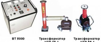
| High-voltage device SKAT-70M | 0 – 70 kV | ±1,5 |
| Micrometer MI 3242 | 0.000 μΩ - 199.9 Ω | ±(0.0025xRmeasurement+2 units ml.r.) |
| Psychometric hygrometer VIT-2 | +15 – +40°С | ±0.2°С |
| Electrical installation parameters meter MI 3100 S | 0.00…19.99 Ohm | ±3 |
- All devices must be verified and testing facilities certified by the relevant government agencies
Test method.
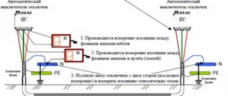
- The method for measuring the insulation resistance of valve arresters is based on determining the electrical conductivity (volume and surface) of the dielectric used to insulate electrical equipment with an E6-31 megohmmeter.
- Measurement of the conduction current of valve-type arresters is carried out for arresters that have shunt resistances and is based on measuring the conduction current through the arrester when a rectified voltage is applied to it by a high-voltage device SKAT-70M, according to the PUE table 1.8.29.
Requirements for ensuring safety during measurements and tests and environmental protection.
- In preparation for measurements, it is necessary to carry out organizational and technical measures when working in electrical installations in accordance with the Labor Protection Rules (Safety Rules) for the Operation of Electrical Installations (POTEE), the requirements of GOST 12.3.019-80 “Electrical tests and measurements. General safety requirements”, when conducting tests, be guided by the requirements of the “Instructions on labor protection when testing valve-type arresters”, “Instructions for safety measures” for instruments used in measuring arresters.
- When taking measurements in electrical installations with voltages up to and above 1000V, it is mandatory to use protective equipment and a set of posters.
- Upon completion of work, it is necessary to clean the workplace, restoring the switching connections broken during the work (if any).
- Work in unlit places is not allowed. The illumination of workplaces during testing should be uniform, without the glare of lighting devices on workers.
- When operating electrical installations, measures must be taken to prevent or limit the harmful effects on the environment of emissions of pollutants into the atmosphere and discharges into water bodies, reduce sound pressure, vibration, electric and magnetic fields and other harmful physical effects, and reduce water consumption from natural sources.
- The intensity of the electric and magnetic fields should not exceed the maximum permissible levels of these factors, the noise impact - the sound power standards of the equipment established by the relevant sanitary norms and standards.
- No additional environmental protection measures are required when performing measurements.
Requirements for personnel qualifications.
- Persons at least 18 years of age, with a special (electrical) education, trained in safe labor methods and techniques, safety precautions, who have passed a medical examination, initial training at the workplace in the scope of labor protection instructions with reflection of the briefing in the journal, signatures of the instructed and the instructing, having studied this Methodology and operating manuals for the devices used.
- Tests and measurements of valve-type arresters must be carried out by a team of at least three people, in which the work performer must have a qualification group for electrical safety of at least IV, the team members must have group III, and must have a personal certificate for testing knowledge of the norms and rules of work in electrical installations .
- If necessary, a guard consisting of team members with electrical safety group II should be posted to prevent unauthorized people from approaching the test facility, connecting wires and equipment being tested. Security team members must remain outside the fence and consider the equipment being tested to be energized. These workers can leave their posts only with the permission of the work manager.
- — persons who violated the requirements of POTEE, labor protection instructions, PTEEP, as well as distorted readings and accuracy of measurements, are liable in accordance with the legislation of the Russian Federation.
Test conditions.
- Tests and measurements of the characteristics of arresters are carried out directly on the measured object in real conditions in the absence of precipitation and dust, at an ambient temperature not lower than +10 C.
- Ambient air humidity is important when conducting high-voltage tests, and should not be more than 90%, because Condensation can lead to insulation breakdown and, accordingly, to failure of equipment (both test and under test). Before conducting high-voltage tests, the test subject should be wiped free of dust, dirt and moisture.
- Atmospheric pressure does not have a special impact on the quality of the tests, but is recorded for recording data in the protocol.
What should the protocol contain?
A standard protocol is drawn up based on the regulatory provisions of Order No. 328n of the Ministry of Labor of Russia and must contain:
- The composition of the commission or the name of the expert testing knowledge in the field of security;
- The name of the organization and the initials of the order to carry out verification actions, as well as the date and place of the action and the seal of the organization;
- Composition of the commission and positions of those present;
- Initials of the employee who is undergoing verification activities;
- Certification topics, that is, a list of questions and assessment of the level of this knowledge;
- Evaluation opinions of an expert commission or the sole opinion of a labor protection specialist/manager.
Also, at the end of this protocol, the responsible member of the commission must sign and, in case of disagreement with the results for a particular candidate, write his motivated opinion. At large enterprises, when conducting mass inspection campaigns, a representative of the state inspection must be present, who also signs when checking the knowledge of the employee.
Important! Negative consequences of completing the procedure in case of failure to confirm knowledge will lead to the employee’s removal from his position while preparing the second stage. At this time, the citizen must thoroughly prepare for the second stage
Sample contents of a blank protocol
Preparation for testing.
- Preparation of the workplace and admission to work are carried out in accordance with the requirements of POTEE for the implementation of organizational and technical measures.
- The switching device must be equipped with an insulating gasket between the holding device or between the moving and non-moving contacts.
- inspect the test object visually, check the surface for chips, cracks, and the tightness of all bolted connections.
- make sure that the condition of the batteries allows measurements to be taken;
- check whether the insulation of the wires and the housing of the measuring instruments and testing equipment are damaged.
- study the consumer's electrical installation;
- check the electrical installation for compliance with the design:
- prepare devices for operation:
- install the devices horizontally on a solid base:
- connect the connecting conductors to the terminals of the device and assemble the test circuit;
- check the correct assembly of the circuit and the reliability of working and protective grounding;
- make sure that the switching devices supplying voltage to the electrical installation under test are in good condition;