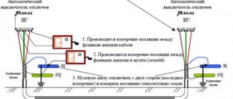
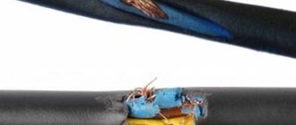
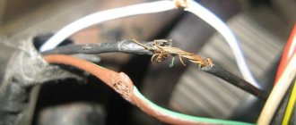
When operating cable power lines, a big problem is insulation breakdown where it cannot be determined either by visual inspection or by using a low-voltage megohmmeter. A good example is the formation of microcracks in cable insulation, which are filled with moisture. When such cracks do not reach from the outer surface of the cable to the conductor, the megohmmeter cannot determine their presence. At the same time, there is a thin layer of insulation between the moisture-filled crack and the conductive core. When operating voltage is applied, this thin layer of insulation cannot withstand and breakdown occurs.
Therefore, cables are tested at a voltage higher than the rated voltage, which makes it possible to identify hidden defects. The test rules are described in the current PUE-7.
For cables with voltages not exceeding 1 kV, only measuring the insulation resistance with a high-voltage (2.5 kV) megohmmeter is used. However, it should not be less than 0.5 MOhm. The only exceptions are 1 kV cables with plastic insulation - they are tested at increased voltage (see Table No. 1).
For cables with voltages above 1 kV, a test with increased voltage of rectified current is used (the use of the term “rectified current” in PUE-7 is due to the fact that in practice rectifiers without filters are used, that is, they have pulsations at the output) according to Table. No. 1. For cables with paper and plastic insulation up to 35 kV, the test duration is 10 minutes, for cables with rubber insulation for 3 - 10 kV - 5 minutes, for cables with any type of insulation for 110 - 500 kV - 15 minutes.
Table No. 1. Rectified current test voltages for various types of power cables
| Paper-insulated cables for voltage, kV | ||||||||||
| 2 | 3 | 6 | 10 | 20 | 35 | 110 | 150 | 220 | 330 | 500 |
| 12 | 18 | 36 | 60 | 100 | 175 | 285 | 347 | 510 | 670 | 865 |
| Cables with plastic insulation for voltage, kV | Cables with rubber insulation for voltage, kV | |||||||||
| 1 | 3 | 6 | 10 | 110 | 3 | 6 | 10 | |||
| 5 | 15 | 36 | 60 | 285 | 6 | 12 | 20 | |||
If we are talking about a plastic insulated cable that does not have armor and is located in an open space, then it is not required to be tested with rectified voltage.
Cables for 110 - 500 kV with any type of insulation can be tested not only with rectified voltage, but also with alternating voltage with a frequency of 50 Hz. In this case, the effective voltage value should be 1.73 of the rated voltage value specified in the documentation for this cable. The cable insulation resistance must be measured with a special megohmmeter, which gives a potential difference at the measuring terminals equal to 2.5 kV. Measurements are made before and after breakdown tests, from which conclusions are drawn about the state of the insulation. But how to interpret the measurement results if the insulation resistance value for cables with voltages above 1 kV is not standardized in PUE-7? There are two options. The first is to either rely on the characteristics declared by the cable manufacturer. If there are none, then move on to the second option. You need to use a rule of thumb - this resistance should be at least 10 megohms.
For cables with voltages from 6 to 35 kV, the leakage current is standardized. In addition, the asymmetry of leakage currents for several cores in a cable can be normalized (the ratio between the minimum and maximum current leakage). When testing for defects in insulation, it is not so much the absolute value of the leakage current that is important, but the dynamics of its change during the test. If the insulation is good, then the current should be stable, showing a slight downward trend. It is possible that at the very beginning a surge in leakage current may occur, which is actually associated with the charge of the parasitic cable capacitance. If the current increases during testing, this indicates the possible presence of insulation defects. If the current value fluctuates, the test time is increased until the direction of the current change stabilizes and the situation with the insulation condition becomes clear, but not more than 15 minutes. PUE-7 standards for leakage currents and asymmetry coefficient are given in table. No. 2.
Table No. 2. Leakage currents and asymmetry coefficients for power cables
| Cable voltage, kV | Test voltage, kV | Permissible leakage current value, no more, mA | Permissible value of the asymmetry coefficient (Imax/Imin), no more |
| 6 | 36 | 0,2 | 8 |
| 10 | 60 | 0,5 | 8 |
| 20 | 100 | 1,5 | 10 |
| 35 | 175 | 2,5 | 10 |
Testing of cables with cross-linked polyethylene insulation
For cables with plastic insulation for 110 - 500 kV, cross-linked polyethylene is used as insulation for such cables. The main problem when testing cables with cross-linked polyethylene insulation with rectified current is the accumulation of space charge in the thickness of the insulation material, which reduces the service life of the cables. In the USA, where they encountered this problem earlier than in our country, the IEEE400.2 - 2013 standard is already in force, which recommends testing cables with cross-linked polyethylene insulation with a sinusoidal or quasi-sinusoidal voltage of very low frequency (VLF - Very Low Frequency) - less 1 Hz. In practice, frequencies from 0.01 to 0.1 Hz are used. In this case, the test time can reach 60 minutes. The presence of the VLF function is an important advantage of the equipment used for testing. And in the future, this function will become more and more relevant due to the increasingly widespread use of cables with cross-linked polyethylene insulation.
This feature, as well as the relative novelty of the insulation material, are the main reasons why the current PUE for cables with plastic insulation for 110 - 500 kV has not yet standardized test parameters. The test methods provided by the cable manufacturer should be used.
Equipment examples
| Cross-linked polyethylene (XLPE) cable testing machines |
Tests and measurements with a megohmmeter
To measure insulation resistance, megaohmmeters of the M 4100/1-5 configuration are used. Their technical indicators are shown in the table.
| Specifications | M 4100/1 | M 4100/2 | M 4100/3 | M 4100/4 | М4Н10/5 |
| Measuring range, kOhm | 0–200 | 0–500 | 1–1000 | 0–1000 | 0–2000 |
| Measuring range, MOhm | 0–100 | 0–250 | 0–500 | 0–1000 | 0–2500 |
| Working part of the scale, kOhm | 0–200 | 0–500 | 0–1000 | 0–1000 | 0–2000 |
| Working part of the scale, MOhm | 0,01–20 | 0,02–50 | 0,05–100 | 0,2–200 | 0,5–1000 |
| Rated output voltage, V | 100+10 | 250+25 | 500+50 | 1000+100 | 2500+250 |
| Basic error, % of the working scale value | 1 | 1 | 1 | 1 | 1 |
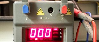
When measuring the insulation of high-voltage equipment, 2500 V megohmmeters are used. Such devices are equipped with their own power source (DC generator) and make it possible to take readings in megohms. Connection is made to the corresponding terminals:
- If you need to measure the insulation resistance relative to ground, the “L” terminal is connected to the current-carrying part of the installation, and the “Z” terminal is connected to its body.
- If the insulation resistance of circuits that are not connected to ground is measured, the terminals can be connected arbitrarily.
- To increase the measurement accuracy and avoid the influence of various factors, you should use the “E” clamp.
The megohmmeter is connected to the test object by flexible wires of minimal length with insulated handles and restrictive rings at the ends. The insulation resistance of the connecting wires is preliminarily measured. It should not be less than the upper measurement limit of the device. The measurements are carried out by 2 people: one rotates the generator handle, and the second touches the parts of the circuit that are to be tested.
To get the correct readings, you need to rotate the generator handle in the range of 90–150 rpm. Megaohmmeters develop the rated voltage with an open external circuit and 120 rpm. The insulation resistance is considered to be the resistance value R-60, which is established on the instrument scale 60 seconds after reaching the normal generator speed. The countdown is carried out strictly after the arrow has assumed a stable position.
Burn function
After high-voltage tests have shown the presence of defects, the locations of insulation damage are determined. Devices that detect such damage are able to pinpoint the location if the resistance between the cable cores is less than 1 kOhm. To ensure such resistance, burning is used - changing the voltage and current supplied to the cable cores according to a certain algorithm in order to completely destroy the insulation of the cores in the place where the defect is present. Ideally, after burning, the two wires are connected to each other by a metal “bridge”. In addition to special equipment, the burning function is present in some models of devices for testing cable insulation.
Features of high-voltage testing of electrical equipment
High-voltage testing of power cables, electrical equipment of substations and other energy facilities is a complex and labor-intensive process. It includes:
- visual inspection of electrical installations;
- checking power transformers;
- testing of switchgear equipment;
- determination of characteristics of grounding devices;
- monitoring the condition of cable lines, searching for places of damage;
- thermal imaging inspection of devices and contact connections;
- determination of insulation resistance of cable lines and electrical wiring;
- in networks up to 110 kV – phasing on the HV side;
- checking the insulation of engines, generators and other power rotating machines;
- testing of high-voltage bushings;
- measurement of partial discharges in equipment insulation;
- in networks with an isolated neutral – monitoring of capacitive ground fault currents;
- testing of secondary circuits;
- checking relay protection and automation devices;
- control of prefabricated and connecting busbars;
- checking load switches, disconnectors.
The engineer carries out comprehensive inspections of electrical equipment with the detection of existing defects and elimination of faults of all levels of complexity. After conducting high-voltage tests in accordance with current regulatory documents, a technical report is drawn up. It reflects the condition of the equipment and contains recommendations for eliminating identified problems.
Examples of cable testing equipment
A variety of equipment is produced for testing power cables with high voltage. Let us give some of the most typical examples.
Test device HPG 70 K
Testing device HPG 70 K
Installation for testing cables with voltage from 0 to 70 kV DC. In this case, the current can be changed within the range from 0 to 10 mA. In the basic configuration, the unit consists of two units: control and indication HSG 1 and a high-voltage unit HPG-70 K. HSG 1 has an analog voltmeter and milliammeter, as well as a timer for up to 60 minutes. To test XLPE insulated cables using the VLF method, a third block is added. It allows you to test cables under voltage of 36 or 52 kV at a frequency of 0.1 Hz.
Burning device BT 5000-1
Burning device BT 5000-1, 14 kV DC, max. 110 A
Depending on the modification, this installation, consisting of four blocks, is capable of testing cables with DC voltages up to 14 kV and a maximum current of 8 - 17 mA, as well as burning insulation at a voltage of 14 kV with a current of up to 110 mA. Some modifications also have a VLF function for testing cables with an alternating voltage of 54 kV with a frequency of 0.1 Hz. Automatic discharge of the capacitance of the cable under test after applying high voltage to it provides an increased level of safety for personnel and equipment.
Installation of HV Tester 25
Installation of HV Tester 25
Thanks to the built-in battery, the SebaKMT HV Tester 25 can be used in a wide variety of conditions.
Often cable testing has to be carried out in an emergency situation when power is not supplied to the work site. In this case, the SebaKMT HV Tester 25 device, powered by a built-in battery, will help out. If the capacity of the built-in battery, for example, during long-term troubleshooting work, is not enough, you can connect the device to a car battery. In this case, the DC output voltage will be limited to 25 kV, and the output current will be limited to 1.5 mA. This makes it possible to test cables with paper and plastic insulation for a voltage of no more than 3 kV, and with rubber insulation for a voltage of no more than 10 kV. The installation has a function for automatically discharging cable capacity. The device is made in the form of a monoblock, which is convenient for transportation.
Insulation test with increased rectified voltage
A schematic diagram of the installation for testing insulation with increased rectified voltage is shown in Fig. 10.10.
Figure 10.10 — Scheme of insulation testing with increased rectified voltage
The essence of the increased rectified voltage test is that the rectified voltage is applied to the test sample through a microammeter. The voltage is gradually increased to the test value and maintained for 10 minutes, recording readings from a microammeter (μA) every minute. The microammeter device must be equipped with a device that completely shunts it. This will prevent it from being damaged by surges of capacitive current - I and absorption current - during charging and discharging the test object. The electrical diagram shows three areas of possible connection of the measuring device. In the first section 1, the circuit connection of the device is most imperfect. In the second 2 and third 3 sections it is necessary to use shielded wires from the device to the object. At test voltages up to 50 kV, a half-wave rectification circuit can be used (Fig. 10.11), and at higher voltages, voltage doubling circuits are recommended (Fig. 10.12).
Figure 10.11 — Scheme for testing insulation with half-wave rectified voltage
An asymmetrical circuit (Fig. 10.12b) is used when testing structures with one grounded electrode.
a – symmetrical voltage doubling circuit; b – asymmetrical voltage doubling circuit
Figure 10.12 — Schematic diagrams of insulation testing with increased rectified voltage
The voltage distribution in the insulation when DC and AC voltages are applied is different. At constant voltage, the voltage distribution after current stabilization is determined by the conductivities of the layers, and at alternating voltage, mainly by partial capacitances. Due to differences in voltage distribution, it is generally incorrect to replace DC voltage testing with AC voltage testing.
Advantages of the insulation testing method with increased rectified voltage:
— the general weakening of insulation is detected by the considered methods in the same way, but the sensitivity of the rectified voltage test method is higher;
— better selectivity of rectified voltage to many types of local insulation defects (punctures, cuts);
— when testing insulation with rectified voltage, there is almost completely no risk of damage due to ionization of gas inclusions, because When exposed to constant voltage, space charges appear at the edges of gas inclusions in a fraction of a second, creating a reverse field and helping to dampen the ionization that has begun.
The disadvantages of the method include the following:
— it is impossible to test the turn insulation of electrical machines;
— if a large resistance is connected in series with the failed insulation element, then the damage may not be detected during testing;
- rectified voltage can cause chemical and possibly electrical reactions that do not occur when tested with alternating voltage. Redistribution of charged particles may occur in liquids, causing the test to give a more favorable picture than actually occurs.
Capacitors of smoothing devices and electrical cables are subjected to rectified voltage tests.
Impulse voltage insulation test
Recently, they have begun to study the electrical strength of insulation with pulsed voltage, similar in form to the impact of overvoltages. For this purpose, damped high-frequency oscillations or long-duration pulses of up to 1 ms are used. While such tests are purely research in nature, it can be expected that they will be widely used in the future. When testing with pulse voltage, pulses of the same sign and combined effects are used.
Advantages of this method:
— effectively detects defects such as cracks and longitudinal delaminations in the grooves of electrical machines;
— quite clearly identifies defects in case and turn insulation;
— the “aging” effect on insulation is reduced compared to alternating voltage.
So, this type of test combines all the advantages of rectified and alternating voltages.
The main disadvantage of this method is that it is difficult to determine whether there was an insulation breakdown during testing or not, because Insulation under certain conditions has the ability to restore impulse strength after a partial or complete breakdown.
High Voltage Test Process
The sequence of high-voltage tests is as follows:
- The serviceability of the testing equipment is first checked. A protective fence is installed.
- When assembling the test circuit, the first step is to ensure protective and operational grounding of the test installation and, if necessary, protective grounding of the housing of the equipment being tested. Before connecting the test installation to a 380/220V power supply, grounding is applied to the high-voltage input of the installation. For this purpose, copper wire with a cross-section of 4 mm2 is used.
- The installation is connected to the electrical network via a plug or switching device with a visible open circuit.
- The wire is connected to a phase, pole of the equipment under test or cable core. It is disconnected only as directed by the test supervisor and only after grounding.
- Before applying voltage, the work foreman checks the presence of team members in the specified places and the distance of unauthorized persons, warns the team about the supply of voltage, and receives responses to the warning. Then he removes the ground from the terminal of the installation and supplies it with a voltage of 380/220V. The value of the test voltage for equipment of each specific category is listed in the “Rules for the operation of consumer electrical installations”.
- Upon completion of the test work, their manufacturer reduces the voltage to zero, disconnects the installation from the mains, grounds the installation terminal and informs the team about this.
- The wires are reconnected or, if the tests are completed, disconnected, after which the fences are removed.