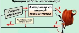
Insulation resistance is the most important indicator characterizing the performance of electrical equipment and its safety for operating personnel. To a greater extent, this parameter concerns cable lines and connecting wires, which are subject to various types of influences during operation. The method for measuring insulation resistance is based on Ohm's law for an electrical circuit.
According to this law, the desired indicator is presented as the result of dividing the voltage applied to the insulating coating by the amount of current flowing through it (Riz = U/I). Diagnostics of electrical wiring and power cables is a mandatory component of preventive measures to maintain their performance at the proper level. Checking the insulation resistance of electrical objects is carried out taking into account the requirements of current standards (PUE, in particular).
Typical causes of insulating coating failure
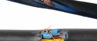
Despite the fact that the sheath of modern electrical cables is made of high-quality and durable material, it nevertheless sometimes loses its protective properties. The latter is usually explained by the following reasons:
- the destructive effects of high voltage and sunlight;
- mechanical damage (deformation);
- temperature violations;
- climatic features of the surrounding area (heat or severe frost, for example).
Violation of the integrity of cable insulation due to mechanical damage
To determine the degree of damage and the admissibility of further operation of wires and cables, measurements of the insulation resistance of cable routes are carried out.
Important! If obvious damage to the cable sheath is detected, organizing and conducting tests loses all meaning.
In this case, the damaged area requires either repair (if this is permissible) or a complete replacement of a section of the cable route or wiring branch.
A timely insulation strength test can prevent a number of unpleasant consequences, including short circuits in the electrical network, injury to people by high voltage and fire.
Insulation resistance standards for electrical circuits and installations
Standard indicators for permissible insulation resistance of electrical installations are introduced separately for each electrical facility. The requirements for this indicator differ significantly for such types of equipment as:
- Power or signal cables laid under various operating conditions.
- Operating industrial electrical installations with working wiring.
- Household appliances that have internal wiring and are equipped with a power cord.
The main indicator, the value of which is used to standardize the permissible insulation resistance, is the voltage acting in the controlled circuit. Moreover, not only its absolute value is taken into account, but also the type of power supply (single-phase or three-phase). The following is a list of some electrical devices and circuits with an indication of their corresponding insulation resistance standard:
- cable wiring located in areas and objects without deviations of climatic conditions from normal - 0.5 MOhm;
- stationary electric stoves –1 MOhm;
- switchboards with electrical wiring and cables located in them – 1 MOhm;
- electrical receivers operating at voltages up to 50 Volts - 0.3 MOhm;
- electric motors and units with a supply voltage of 100-380 Volts - at least 0.5 MOhm.
And finally, according to the PUE, for any devices connected to electrical lines with an operating voltage of up to 1 kV, this figure cannot be less than 1 MOhm. Studying the accompanying documentation for a specific sample will help determine what the resistance of the protective shell of the equipment in use should be.
Acceptable insulation resistance values
Tricks with a megaohmmeter
About tricks with a megaohmmeter, I can only note that we have one employee whom we tested at 500 volts, here, as he says, the main thing is to keep the ends tight and not let go. Attention!!! I don’t advise you to repeat this!!! . It was a terrible sight, of course. But theoretically, the current is small and the thermal effect is not annoying.
In general, I wish you good luck in your work with a megohmmeter, and be careful, because our profession is not only very interesting, but also quite dangerous. TB above all!!!
Read more about measuring Rx cable with a megohmmeter
You can also familiarize yourself with a multimeter
Measuring instruments
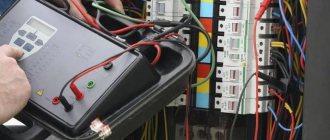
Instruments for measuring insulation resistance are conventionally divided into two groups. These are: panel AC meters and small-sized devices (they are carried manually). The first samples are used in conjunction with mobile or stationary installations that have their own neutral. Structurally, they consist of relay and indicator parts and are capable of continuous operation in existing networks of 220 or 380 Volts.
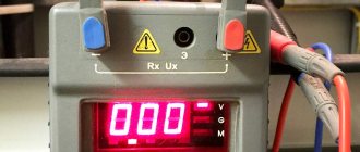
Most often, measurements of the insulation resistance of electrical wiring are organized and carried out using mobile devices called megohmmeters. Unlike a conventional ohmmeter, this device is intended for measurements of a special class, based on assessing the state of insulation when exposed to high voltage.
Please note: Pulse messages with an amplitude of about 1-2 kV are generated by the megohmmeter itself.
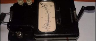
Known models of these devices are analog and digital. In the first of them, a mechanical principle is used to obtain the required value of the test voltage (as in a “dynamo”). Experts often call them “pointer”, which is explained by the presence of a graduated scale and a measuring head with an arrow.
These devices are quite reliable and easy to use, but today they are obsolete. The main inconvenience of working with them is their significant weight and large dimensions. They have been replaced by modern digital meters, the circuit of which includes a powerful generator assembled on a PWM controller and several field-effect transistors.
Such models, depending on the specific design, can operate both from a network adapter and from autonomous power supply (one option is rechargeable batteries). Indications for measuring the insulation of power cables in these devices are displayed on the LCD display. The principle of their operation is based on a comparison of the parameter being tested and the standard, after which the received data enters a special block (analyzer) and is processed there.
Digital instruments are characterized by their relatively light weight and small size, which is very convenient when conducting field tests. Typical representatives of such devices are the popular Fluke 1507 meters (photo on the left). However, to work with an electronic circuit, you need a certain level of qualifications that allows you to prepare the device and obtain a minimum error in measurements. The same approach will be required when handling an imported digital product labeled “1800 in”.
It is important to note that it makes no sense to check the insulation of cable products using conventional measuring instruments. Neither the most “advanced” multimeter, nor any other similar model is suitable for these purposes. With their help, it will be possible to make only an approximate estimate of the parameter obtained with a large percentage of error.
Preparing for measurements
Preparation for conducting insulation tests comes down to choosing a device that is suitable in its characteristics for the stated purposes, as well as organizing the measurement scheme. The following devices are considered the most suitable for most cases:
- Megaohmmeters type M4100, having up to five modifications.
- Meters of the F 4100 series (models F4101, F4102, designed for limits from 100 Volts to one kilovolt).
- Devices ES-0202/1G (limits 100, 250, 500 Volts) and ES0202/2G (0.5, 1.0 and 2.5 kV).
- Digital device Fluke 1507 (limits 50, 100, 250, 500, 1000 Volts).
Megaohmmeter M4100
Megaohmmeter-F-4100
Megaohmmeter-ES-02021G
Fluke 1507 Digital Meter
Important! For measurements, only pre-verified devices are taken, which must have a manufacturer’s license.
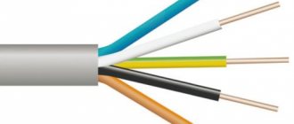
According to the PUE, before measuring insulation resistance, you will need to prepare a diagram for connecting the megohmmeter to the elements of the object being tested. For this purpose, the meter kit includes a pair of flexible wires no more than 2 meters long. Their own insulation resistance cannot be less than 100 MΩ.
We also note that for the convenience of checking the cable insulation with a megohmmeter, the working ends of the wires are marked, and special tips are put on them on the device side. On the return side, the measuring cables are equipped with alligator clips with special probes and insulated handles.
Test methods used
Even before checking the condition of the insulation, it is important to decide on the object where you want to evaluate its quality. It can be:
- Electrical wiring.
- High voltage power cables.
- Low voltage power lines.
- Control wires.
For each of these electrical categories, individual methods for measuring insulation resistance are selected. Let's consider all the listed options in more detail.
Wiring
Before starting measurement procedures, electrical wiring and distribution boxes are inspected for breaks and obvious damage. After this, the places where the wires are connected to standard sockets and switches are examined.
Important! It is allowed to begin measuring insulation resistance only after the wiring is completely de-energized and all consumers at the facility are disconnected from it.
Measuring the insulation resistance of electrical wiring using a digital device Fluke-1507
In a single-phase network, to determine the required parameter, you will need to perform the following operations:
- First, the megohmmeter probes are connected between the phase and neutral conductors of the wiring.
- Then the insulation resistance between the phase and central conductor of the protective grounding is determined.
- The number of measurements taken corresponds to the set of wires in the line.
If, when taking readings, the megohmmeter shows a resistance of less than 0.5 Mohm, the electrical line will have to be divided into shorter segments. Based on the results of subsequent inspections of each of them, there is an area with unsatisfactory insulation quality. It will subsequently need to be completely replaced.
High voltage power cables (preparation)
Before measuring the insulation of a power cable, the latter is checked to ensure that there are no dangerous voltages on it. In addition, to prepare the measuring circuit, you will need to perform the following operations:
- First of all, the residual charge must be removed from the current-carrying conductors using portable grounding.
- Then the cable is completely cleaned of dust and dirt that interfere with the measurement process.
- After this, you will need to familiarize yourself with the cable’s passport data (the required parameter obtained from the results of factory tests is indicated there).
- The last operation is necessary in order to determine in advance the operating limit set on the device.
Preparing a cable line for insulation resistance measurements
Important! Before measuring the cable insulation resistance, it is necessary to carry out a control check of the megohmmeter for serviceability.
This operation consists of monitoring the readings on the instrument scale with the measuring ends closed and open. In the first case, the arrow moves closer to “zero”, and in the second case it shows “infinity”.
Power cables (measurements)
Measuring insulation resistance with a megohmmeter begins with a control check of each phase in relation to a grounded steel shell. And only after this the resistance between the individual cores is checked (photo on the left). In the process of taking readings, it is unacceptable for the measuring ends to come into contact with each other, as well as to come into contact with grounding structures and the steel shell.
a) the insulation resistance between the phase and the grounded sheath of the cable is measured, b) the resistance between the phases of the cable line is measured, respectively, “A” - “B”, “B” - “C” and “A” - “C”.
If it is found that the insulation resistance is below the permissible level, additional measurements are carried out in accordance with the requirements of the Electrical Installation Regulations. They involve measuring the insulation of all phases in relation to the ground and estimating the conductivity between phase conductors.
Please note: To improve the accuracy of readings indicating the value of wire insulation resistance, several measurements are taken.
Their total number varies: for a 3-core cable within 3-6 measurements, and for a five-core cable it may require 4, 8 or even 10 approaches.
Measuring the insulation resistance of a power cable in a private home
Since there are several measurement schemes for three-phase circuits, you should familiarize yourself with the option proposed by the manufacturer using the same passport. Before accurate readings are displayed on the megohmmeter scale, according to GOST 3345, at least 60 seconds must pass, but no more than 5 minutes (from the moment the ends are connected and high voltage is applied). If during this time, due to high humidity, for example, it was not possible to determine the readings (the needle did not deviate by the calculated value), the operation will have to be performed again.
Scheme for measuring the insulation resistance of a high-voltage cable
Before retesting, the residual charge must be removed again by applying grounding. Then you will need to switch the device to the desired limit and repeat the control measurements. According to safety regulations, this operation must be carried out with dielectric gloves. It is recommended to follow the instructions in pp. 1.7.81, 2.1.35 PUE, which stipulate safe work conditions. The main ones are given below.
- for zero operating and protective busbars, the insulation must be equivalent to the protective coating of phase conductors;
- on the side of the supply voltage sources and its receiver, the neutral conductors should be disconnected from the grounded elements of the circuit;
- Measurements in power electrical wiring are carried out only when the voltage is completely removed and the input circuit breakers or switches are turned off.
The last point is supplemented by the mandatory requirement to remove the fuses, turn off all existing receivers and unscrew the light bulbs. The measurement schemes proposed in the instructions differ only in their number (4 and 8 instead of 3 and 6) and the need to use the “Screen” protective terminal on the megohmmeter.
Low voltage power cables
When working with low-voltage power lines, they are first checked to ensure that there are no dangerous voltages on their elements. Similar to the high-voltage cables already discussed, before examining these products, you will need to perform the following operations:
- First, a dangerous residual charge is removed from the current-carrying conductors using portable grounding.
- Upon completion of this operation, the cable sheath and its working cores are completely cleaned of dust and dirt.
- Then the documents (passport, for example) are studied, which indicate the standardized insulation resistance for the test sample.
- The last operation is carried out with the aim of approximate estimation of the measured value and selection of the desired measurement limit on the device.
To carry it out, take a megohmmeter designed for a generation voltage of 1000 Volts. Upon completion of all preparatory operations, proceed directly to measurements. Their order can be represented as the following sequence of actions:
- First, the required resistance is measured between the phase conductors of the cable line under test (“A” - “B”, “B” - “C” and “A” - “C”).
- Then, the insulation state of each phase relative to the neutral wire (N) is assessed in turn.
- The following is a sequence of measurements between each phase and the PE ground wire (carried out when checking a three-phase five-core conductor).
- To carry out the last operation, the neutral wire is disconnected from the grounding bus, after which the resistance between the N and PE conductors is measured.
Upon completion of each next action, it is necessary to “remove” the residual charge in the manner already described.
Control cables (preparation)
In this case, it will be possible to check the resistance only if the following requirements are met:
- The ambient temperature should be within the range from –30 to +50 degrees (with humidity up to 90%).
- They influence the admissibility of working with a particular type of megohmmeter in a particular situation.
- The measurement conditions (the length of the monitored cable, in particular) and the operating voltage are selected depending on its brand.
- If there is no passport for the cable product, a test voltage of 0.5 to 1 kV is applied to it according to the PUE (Table 1.8.39).
Please note: It is allowed to carry out tests together with all equipment connected to the cable (magnetic starters and protective relays installed in the line).
Before testing resistance, be sure to be familiar with safe cable handling techniques. They boil down to compliance with the following rules:
- Only specialists with the 3rd tolerance group or higher are allowed to take measurements under voltages up to 1 kV;
- the cable under test must be disconnected from the power supply, after which the residual charge is removed from it;
- Before starting measuring operations, you must ensure that there are no unauthorized persons near this place.
Voltage is applied to the current-carrying conductors using probes with insulated handles of the “holder” type. In addition, for safety reasons, it is prohibited to touch the conductive busbars to which the turned on megohmmeter is connected. Upon completion of the current tests, the residual charge must be removed from the control part of the cable. To do this, portable ground connections are used or a special function of the measuring device is activated (available in some models).
Control cables (work order)
The procedure for testing the insulation protection of control cables is similar to the provisions developed for low-voltage wiring lines (up to 1 kV). An exception is the clause on disconnecting current-carrying conductors from load equipment. Due to the small magnitude of the transmitted signal, this is not necessary in this situation.
To carry out the tests, you will need a digital or analog megohmmeter, according to the passport, designed for operating voltages from 0.5 to 2.5 kV. The order of measurements in this case looks like this:
- First, on the side of the cable being tested, the leads of the current-carrying conductors are carefully cut and cleaned, and then separated from each other to some distance (about 5-10 cm).
- Next, each wire is connected in turn to the “+” of the megohmmeter, and all other wires are twisted and connected to the “ground”.
- The second input (“–”) of the device is also connected there (see figure below).
- Test voltage is then applied to the working cable.
- When using modern digital devices, an external power source (electrical network or battery) will be required.
- The tests last for at least a minute, after which the result is recorded on a scale and then entered into the logbook.
- Further, all the described operations are performed with each signal core separately (it is connected to the device, and all others are twisted and connected to the second contact, which in turn is connected to the ground.
At the end of the measurements, the residual charge is removed from the working conductors, and the megohmmeter is allowed to “settle” until the next series of tests. The duration of the pause allocated for this depends on the specific type and brand of the device. The following measurements are carried out taking into account the frequency of the insulation test.
Low voltage power cables
Before measuring insulation resistance, you need to make sure that the cable is not supplied with dangerous voltage levels. The cable must be disconnected before starting work. Next you need to do the following:
- Using portable grounding, the residual charge is removed.
- The cable is cleaned of dirt.
- The insulation resistance value, which is indicated in the technical documents, is determined and, in accordance with it, the indicator is set on the scale of the measuring device.
The insulation resistance of low-voltage cable lines is measured using a device capable of operating with voltages up to 1000 Volts. The algorithm of actions is as follows:
- A megohmmeter is connected in pairs to all phase wires in the cable.
- Then each of the phase wires is considered in relation to the neutral wire.
- Each phase wire paired with a ground wire is measured.
- The neutral and ground wires are checked.
After working with each pair of wires, it is necessary to remove the residual charge.
Documentation of measurement results
Based on the results of the work carried out, a separate document is prepared, which records all the necessary data.
Important! According to the PUE, in three-phase networks it will be necessary to perform at least 10 measurements, each of which is taken into account in the protocol for measuring insulation resistance.
In household single-phase circuits, three measurements will be sufficient. The last lines of the completed protocol must contain a phrase about the compliance of the results obtained with the requirements of the PUE.
In addition, they include the following data:
- Date and scope of surveys performed.
- Information about the composition of the work team (service personnel).
- Measuring instruments used during testing.
- Their connection diagram, ambient temperature, as well as work conditions.
Upon completion of recording the measurements, the log with the corresponding entries is put away in a safe place, where it is stored until the next tests. Measurement reports saved in this way may be required at any time in order to serve as evidence of the serviceability of a damaged product in emergency situations.
The finished protocol must be certified by the signature of the work contractor and the inspector appointed from the operational staff. To draw up measurement reports, it is allowed to use a regular notepad, but a more legal and reliable way is to fill out a special form (a sample of it is given below).
Sample insulation resistance measurement protocol
A pre-prepared protocol form contains paragraphs indicating:
- The procedure for carrying out measuring operations.
- The measuring instruments used.
- Basic standards for the controlled parameter.
In addition, the form of electrical wiring measurement reports contains ready-made tables prepared for filling out. In this form, the document is compiled on a computer only once, after which it is printed on a printer in several copies. This approach saves time on preparing documentation and gives measurement reports a finished, official look.
Frequency of insulation resistance measurements
The requirements of the PUE provide for certain deadlines, taking into account which measurements of insulation resistance with a megohmmeter are organized and carried out. For everyone who wants to get a closer look at the frequency of measurements of insulation resistance in lighting networks of outdoor installations, as well as in their power part, we suggest studying the following sections.
When and under what conditions are measurements taken in outdoor installations?
Examination of electrical wiring and other electrical objects (measurement of protective insulation resistance) is carried out in the following mandatory cases:
- During the manufacture of products at the enterprise that produces them.
- Directly at the electrical facility before the start of installation work.
- Upon their completion, before putting the facility into operation (before applying voltage to it).
- After serious accidents and detection of unacceptable defects.
- When carrying out maintenance within the time limits specified in the technical documentation for a specific type of equipment.
If these requirements are violated and the established deadlines for insulation resistance tests are not observed, the likelihood of malfunctions in the operation of electrical installations increases. Violators may face penalties and fines provided by law. Therefore, those responsible for electrical equipment at enterprises prepare plans for insulation measurements in a timely manner.
Safety regulations
The technique used to measure insulation resistance must ensure that safety requirements are met. You must adhere to the following rules:
- All manipulations when measuring insulation resistance must be performed with dielectric gloves. Failure to comply with this requirement increases the risk of injury.
- When carrying out measurements, no unauthorized persons should be near the equipment. It is advisable to post warning posters near the place of work.
- When using probes, only touch their insulated parts.
- Before each measurement, it is imperative to remove the residual charge using a portable grounding device.
- It is important to check the humidity level. If it is higher than permissible, measurements cannot be carried out, as this can be dangerous.