The reliability of operation of TN electrical networks with a voltage class of up to 1 kV largely depends on the response parameters of protective equipment that disconnects the emergency section when overcurrents occur. There are several methods that allow you to check the reliability of the operation of circuit breakers; today we will consider in detail one of them - measuring the resistance of the phase-zero loop. To better understand the process, we will begin with a brief description of the terminology, after which we will move on to the electrical testing methodology using a special device MZC-300.
What is a zero loop
In electrical installations with voltages up to 1000 volts with a solidly grounded neutral, a metal connection of the parts to be grounded with the grounded neutral of the electrical installation is required. For such installations, the resistance of the loop formed when a phase is short-circuited to the device body must be measured. This resistance is equal to the sum of the impedances of the phase wire, the phase of the power transformer and the neutral wire.
Read also: What is ordinary wine?
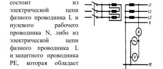
A phase-zero circuit (loop) in electrical installations with a solidly grounded neutral is formed when the phase wire is short-circuited with the neutral wire or the body of the electrical equipment. This usually occurs when the insulation of the electrical wiring is damaged. In the event of such an accident, protection devices (circuit breakers, fuses) must turn off the electrical installation as soon as possible to ensure electrical safety conditions.
A phase-zero loop is a circuit consisting of a connection of a phase and neutral conductor. The resistance of the phase-zero loop depends on the cross-section of the cable cores, its length, and the transition resistances in the junction boxes of a given line. Measurements are carried out on the section of the line furthest from the protection device.
The need for measurements
Loop resistance is measured in the following cases:
- During commissioning, after repair, modernization or re-equipment of installations.
- Requirement from various control services, for example Oblenergo, Rostechnadzor, etc.
- According to the consumer.
During electrical measurements, certain parameters of the F-N loop are established, namely:
- Total circuit resistance, which includes:
electrical resistance of the transformer at the substation;
similar parameter of the linear conductor and working zero;
Numerous transient resistances formed in switching equipment, for example in protective devices (AV, RCD, differential circuit breakers), starters, manual switches, etc. Also influenced by the cross-section of conductors, cable insulation, grounding of the transformer neutral, parameters of the RCD or other protection of electrical installations.
- Short circuit current (ISC). In principle, it can be calculated using the formula: ISC = UН / ZП, where UН is the nominal voltage level in the electrical network, and ZP is the total loop resistance. Considering that protective devices during a short circuit must automatically turn off the power according to established temporary standards, the following condition must be met: ZП*IAB <= UН. In this case, IAB is the current at which the AV or other protection device is triggered; its value must be inferior to ISC.
Before describing detailed measurement techniques, it is necessary to briefly describe the instrument that will be used in the process - the MZC-300. We chose this device because it is most often used by measurement laboratories.
How the network is measured
To understand this, it is necessary to consider a circuit in which there is a consumer connected through a regular outlet. So, as mentioned above, phase and zero are supplied to the socket. In this case, there is a loss of voltage up to the outlet due to the resistance of the main cables and wires. This has been known for a long time; this process is described by Ohm’s formula:
R=U/I.
True, this formula describes the relationship between the magnitudes of direct electric current. To convert it to alternating current, you will have to take into account some indicators:
- Active component of network resistance.
- Reactive, consisting of a capacitive and inductive part.
What does it mean?
It is necessary to understand that the electromotive force that appears in the windings of the transformer forms an electric current. It loses its voltage when passing through the consumer and the supply wires. In this case, the current itself overcomes several types of resistance:
Accurate method for determining single-phase fault current
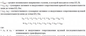
1.1 The exact method for determining the single-phase short circuit current is presented in GOST 28249-93, formula 24, and is calculated using the formula:
Using this method, it is possible to determine with a high degree of accuracy short-circuit currents with known resistances of the positive, negative and zero sequence of the phase-zero circuit.
Unfortunately, in practice, this method is not always possible to use, due to the lack of reference data on positive, negative and zero sequence resistances for cables with aluminum and copper conductors, taking into account the methods of laying phase and neutral conductors.
Instruments for measurements
You can measure the main indicators of the F-N circuit using two types of devices. The former can only be used after the voltage has been removed, while the latter can work under load. There are also differences in the amount of information displayed. Simple devices provide the values necessary for calculating Ik. A more complex design of the meters allows you to immediately display the value of Is.
Experts recommend using the following models of devices:
- MZC 300 is a modern microprocessor meter, the nuances of which we will describe below.
- M-417 - proved itself to be the best many years ago. Tests are carried out using the voltage drop method. In this case, the meter can be used under operating line voltage in networks with a solidly grounded neutral. The circuit under test opens in 0.3 s. You will need to perform calibration first.
- IFN-200 is designed for testing circuits with a resistance of up to 1 kOhm, with a permissible voltage from 180 to 250 V. In addition to measuring the F-N circuit, it is also capable of functioning in other modes. The IFN-200 memory can store data on thirty-five extreme calculations.
Resistance meter IFN-200
Brief description of MZC-300
Let's look at the appearance and main elements of the MZC-300 meter.
Location of the main elements of the MZC-300 device
Designations:
- Information display. A full description of its fields can be found in the user manual.
- "Start" button. Starts the following measurement processes:
- ZP, recall, is the total resistance of the F-N circuit.
- ISC – expected short-circuit current.
- Active resistance is necessary for calibrating the device.
The start of each measurement is accompanied by a characteristic sound signal.
- SEL button. Serves for sequential display of all loop characteristics obtained as a result of the last measurement on the information display. In particular, the following information is displayed:
- ZP parameters.
- Expected IKZ.
- Level of active and reactive resistance (R and X).
- Phase angle ϕ.
- Z/I button. At the end of the test, switches the display of characteristics between the expected ISC and ZP.
- Button to disable/enable the measuring device. If, when starting the device, you press “SEL” simultaneously with this button, the meter will go into auto-calibration mode. Its detailed description can be found in the user manual.
- Connector for connecting a probe in contact with the working zero, PE or PEN conductor. The corresponding designation is marked on the body of the device.
- Connector for a probe connected to one of the phase wires. As a rule, marked with the letter “L”.
- Like the i connector, unlike the test lead sockets, it is used only in automatic calibration mode. On the device body they are designated as “K1” and “K2”.
Why check the resistance of the phase-zero loop?
Checking the resistance of the phase-zero loop is an important step in checking the functionality of the electrical network. This operation is performed to ensure a number of conditions:
- Installation of the required circuit breaker (RCD). The ability to accurately calculate the short-circuit current, which will ensure the selection of a machine that operates without delay.
- Selection of cable cross-section for solidly grounded neutral and phase conductor.
- Determining the need to install a stabilizing device in case of frequent fluctuations in alternating current in the network.
- Checking the possibility of ensuring selectivity during equipment operation.
- In many cases, when putting a cable line into operation, approval of electrical installation products is required from Rostekhnadzor authorities. Before issuing permitting documentation, responsible persons are required to provide protocols for measuring resistance on the phase-zero loop and other tests of the circuit.
From an economic point of view, checking the phase-to-zero resistance allows you to select the optimal electrical installation products without overpaying for extra indicators or cross-sections.
The need to measure F-N resistance
The method allows you to compare the actual resistance measured in practice with the projected indicator included in the planning. If the circuit is installed properly, both values will coincide, which means that the operation of the line will be safe.
Purposes of phase-zero loop measurement:
- checking installation quality to find errors and weak areas;
- safety assessment of automatic protection equipment;
- testing of electrical installations upon delivery and acceptance into operation after reconstruction or installation;
- at the request of regulatory organizations, for example, Rostechnadzor;
- at the request of the owner of the main line or electrical units.
Valera
The voice of the construction guru
Ask a Question
The length of the cable line from the transformer to the consumer outlet is measured in hundreds of meters. There are many connectors in the line design that lose voltage even when installed correctly. Internal resistance measurements are carried out to identify negative areas and enhance protection on them.
How often are measurements taken?
The frequency of readings and calculations is carried out in accordance with the preventive maintenance schedule developed by electrical engineers. The document contains recommendations for maintenance and testing of systems, and is signed by the head of the enterprise.
Recommended inspection periods in accordance with GOST R 50.571 – 2007:
- for electrical appliances and installations operating in areas of increased explosion hazard - once every 2 years;
- if automatic protection fails, an immediate unscheduled check is performed;
- mandatory - during acceptance and commissioning, when putting equipment into operation;
- for standard conditions, after successful completion - once every 3 years.
At the request of the owner or the recommendation of the responsible person regarding technical inspection and monitoring of electrical equipment, such measurements are made more often.
High precision instruments used
For phase measurements and calculations, both standard ammeters and voltmeters, the use of which is not difficult, or highly specialized instruments can be used. The latter ensure the highest possible accuracy of the obtained data on power grid parameters. The following measuring instruments are most widely used.
M417 is a reliable, proven device designed specifically for measuring resistance in a phase-zero circuit. One of the features of this device is the ability to carry out all work without removing the power, which greatly simplifies monitoring the state of the electrical network. This device uses the voltage drop method, ensuring the highest possible accuracy of the resulting calculations. It is allowed to use M417 in a circuit with a solidly grounded neutral and a voltage of 380 Volts. The only drawback to using this device is the need to calibrate the device before starting work.
MZC-300 is a new generation measuring device, which is based on a powerful microprocessor. The devices use a voltage drop method with a 10 ohm resistance connected. MZC-300 provides a measurement time of 0.03 seconds and can be used in networks with a voltage of 180-250 Volts. To ensure data accuracy, the device is connected to a distant point in the network, after which the Start button is pressed, and the result obtained is displayed on a small digital display. All calculations are performed by a microprocessor, which greatly simplifies phase control.
IFN-200 is a multifunctional device that allows you to perform phase measurements. The device operates with a voltage of 180-250 Volts. There are appropriate connectors to simplify connection to the network, and using this device does not present any difficulty. The limit on the measurement in the circuit is 1 kOhm, when exceeded, the protection is triggered and the device is turned off, preventing it from overloading. The device is based on a powerful microprocessor and has a built-in memory for the latest 35 calculations.
What determines the voltage and current during a short circuit?
Above I said that a short circuit can occur at any point on the line. Let's figure out how the current and voltage will depend on the location of the short circuit.
A short circuit is a physical phenomenon. Short circuit current is a parameter of the power supply network, measured in amperes or kiloamperes (kA).
The German physicist Ohm has taught us since school years that voltage and current are determined through the resistance of the circuit:
Short circuit current, like any current, is also calculated according to Ohm's law and depends on the voltage and resistance in a given section of the circuit. Since the resistance of wires in real life is not only what the multimeter shows, but also the inductive component, we will write Ohm’s law for short-circuit current in a more general form:
In the numerator U is the rated voltage in the network (no-load voltage at the output of the transformer at the transformer substation). The number that is obtained in the calculations in the denominator is the total resistance of the circuit Z, on which the short-circuit current depends. Let's consider a single-phase power supply circuit for an apartment and a real case of a short circuit with a shorted hair dryer:
Short circuit at the end of the supply line (minimum short-circuit current)
The diagram shows the impedances of various sections of the supply network:
- Z1 – internal resistance of the transformer at the substation, taking into account the recalculated resistance of the high-voltage part,
- Z2 – cable line from the transformer substation to the distribution point (DP) of the apartment building,
- Z3 – cable line from the distribution point to the apartment panel,
- Z4 – cable from the panel to the socket in one of the rooms,
- Z5 – carrying from an outlet to a closed hair dryer.
The hair dryer burned out and caused a short circuit
Here's what a voltage level graph might look like in different areas - from the terminals of a transformer at a substation to a shorted hair dryer plug:
Voltage drop to zero as a result of a short circuit at the end of the line
The voltage drop is accompanied by the release of heat in all parts of the supply line. In powerful sections with a large cross-section of wires, the share of the “indoor” short-circuit current is negligible, so the drop there is small (sections with resistance Z1, Z2).
Article about voltage drop. Calculation in low-voltage circuits and in DC circuits, without taking into account the reactive component.
In connection with the voltage drop as a result of a short circuit, it can be noted that this will be noticeable on parallel loads connected, for example, to the same RP. In the event of a short circuit or severe overload of one of the consumers, the light bulbs in neighboring houses and entrances will begin to burn dimmer. Has it happened?
And here’s what the change in short-circuit current from the source to the fault point might look like:
Decrease in current when moving away from the power source
The typical value of the short-circuit current at the terminals of a transformer with a power of up to 1000 kVA, which is used to power urban consumers, is about 10 kA. But in the sockets of our apartments, the short-circuit current can be about 1000 A. In the private sector and rural areas, the value of the short-circuit current can be much less - up to 100 A.
Transformer at a 10000/0.4 kV substation with a power of 1000 kVA with a solidly grounded neutral of the secondary winding. This is roughly what our “districts, neighborhoods, residential areas” are powered by.
Preparatory stage
Almost all methods of measuring the phase-zero circuit do not allow obtaining accurate information about such characteristics as ZP and ISC. This is due to the fact that the vector nature of voltage is not taken into account. Simply put, simplified short circuit conditions are taken into account. When testing electrical installations, such approximation is allowed only in cases where the level of reactance does not have a significant effect.
Before you begin measuring the characteristics of the F-N loop, you should first carry out a number of preliminary tests. In particular, check the continuity and resistance level of the protective lines. After this, measure the resistance between the ground loop and the main metal elements of the building structure.
Review of techniques
There are different methods for checking the phase-zero loop, as well as a variety of special measuring instruments. As for measurement methods, the main ones are:
- Voltage drop method. Measurements are carried out with the load disconnected, after which a load resistance of a known value is connected. The work is performed using a special device. The result is processed and, using calculations, a comparison is made with standard data.
- Circuit short circuit method. In this case, the device is connected to the circuit and an artificial short circuit is created at a distant point of consumption. Using the device, the short-circuit current and the response time of the protection are determined, after which a conclusion is drawn about compliance with the standards of the given network.
- Ammeter-voltmeter method. The supply voltage is removed and then, using a step-down transformer running on alternating current, the phase wire is closed to the body of the existing electrical installation. The received data is processed and the required parameter is determined using formulas.
The main method of such testing was to measure the voltage drop when connecting a load resistor. This method has become the main one due to its ease of use and the possibility of further calculations that need to be carried out to obtain further results. When measuring a phase-zero loop within one building, the load resistance is turned on at the farthest section of the circuit, as far as possible from the point of power supply. The devices are connected to well-cleaned contacts, which is necessary for reliable measurements.
First, the voltage is measured without a load; after connecting an ammeter with a load, the measurements are repeated. Based on the data obtained, the phase-zero circuit resistance is calculated. Using a ready-made device designed for such work, you can immediately obtain the desired resistance on a scale.
After the measurement, a protocol is drawn up in which all the necessary values are entered. The protocol must be in a standard form. It also includes data on the measuring instruments that were used. At the end of the protocol, a summary is made of the compliance (non-compliance) of this section with the regulatory and technical documentation. A sample of filling out the protocol looks like this:
Protocol on measurements of the “phase zero” circuit
Based on the measurements taken, a special protocol is drawn up. It is used to store recorded readings, as well as to carry out comparative analysis with subsequent tests.
The protocol displays the following information:
- the date of the;
- protocol number;
- purpose of testing;
- information about the organization conducting the tests;
- information about the customer;
- current climatic conditions: atmospheric pressure, temperature and humidity;
- measurement range, accuracy class and type of release;
- meter used for testing;
- recorded readings;
- test result;
- positions, names and signatures of the persons who carried out the measurements and checked the protocol.
Purposes of measuring the phase-zero loop
Electrical wiring fire protection
In order to prevent a fire from occurring in the event of a short circuit in the electrical wiring, automatic switches are installed in the electrical circuit, which we can see, for example, in an apartment panel. When a short circuit current flows, which is hundreds of times greater than normal, they turn off almost instantly (hundredths of a second).
In such a short period of time, nothing simply has time to “heat up and ignite”
A working machine operates at a current 5-10 times higher than the rated current, i.e., if it is marked C16, then instantaneous shutdown is guaranteed to occur at a current of 160A, and if C63, then 630A. If the short circuit current does not reach the operating threshold of the circuit breaker, it will not turn off instantly, but under the conditions of a current overload (5-30 seconds), which is certainly enough to ignite the surfaces in contact with the electrical conductor.
To ensure fire safety, it is necessary that the circuit breakers not only be in good working order, but also that the current during a short circuit is sufficient for instantaneous operation. You can check the actual short-circuit current only by directly measuring it with a device, which is colloquially called a “loop meter” (officially a “harmonic microohmmeter”).
Protection against electric shock from indirect contact
Based on the measured value of the single-phase short circuit current, the automatic operation time of the protective device is determined. This response time must be within the limits of the PUE Requirements (clause 1.7.79) for protection against electric shock during indirect contact by automatically turning off the power.
What is a short circuit?
Many people know such a stable expression - “short circuit”. In addition to the name of a famous blockbuster from the 90s, the average person associates these words with a common cause of fires. There are many myths and cliches floating around on this topic. I decided to figure out what was what and why all this was needed.
A short circuit (SC) is a mode of operation of the electrical network, or a phenomenon in which the maximum possible current flows in the circuit at the point of the circuit. This event is difficult to predict and emergency, and the sooner it stops, the better. When a short circuit occurs, all the energy of the power source is spent only on heating the wires. In addition, dynamic (mechanical) consequences are possible. This process is usually very fleeting and explosive, since the thermal energy released is colossal. If you do not stop this disgrace as quickly as possible (we will look into how this is done below), then short circuit can lead to large material and human losses.
The shutdown time of household circuit breakers during a ground fault must be less than 0.4 s (PUE 1.7.79, 7.1.72). If the speed is not ensured due to low short-circuit current, shutdown should occur through devices that respond to differential current (RCD, RCBO), the response time will be (according to GOST) less than 0.04 s.
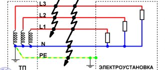
A short circuit can occur between any points in an electrical circuit that have different potentials. Here's what it looks like in three-phase form:
Short circuits in the power supply system with the TN-S grounding system. Who will see the error in the diagram?
The figure conventionally shows the secondary winding of a step-down transformer installed in a transformer substation (TS), a five-wire power line and a three-phase electrical installation. The electrical installation can be a private or apartment building, or maybe something industrial.
Closures can come in different forms:
- two- and three-phase (phase-to-phase),
- one-, two- or three-phase to neutral N or protective PE conductor.
If we consider the safest grounding system TN-S with a solidly grounded neutral of the transformer, then most often (in practice - about 90%) a single-phase short circuit occurs between the phase wire and the neutral N (or the protective conductor PE). Therefore, further we will consider a simpler, single-phase option:
Short circuit to neutral and protective conductors
I recommend my article: How three-phase voltage differs from single-phase. And linear from phase.
A short circuit can happen anywhere - even near a transformer substation (TS) due to the inattention of an excavator operator, or in an apartment because of a cat that dropped a Christmas tree. In any case, the protection must work clearly, minimizing the consequences of a short circuit.
By the way, our cat once dropped our Christmas tree. They threw her out of the 5th floor.
Formulas for calculation
After taking measurements and recording the results in a protocol in the established form, it is necessary to carry out some calculations that will allow you to check the performance of the RCD and cable lines. Calculations are reduced to the use of standard electrical formulas, in accordance with the PUE:
- Phase-zero loop resistance formula:
Z = ZS + ZT / 3,
Z – the required value of the resistance of the phase-zero loop,
ZS is the total resistance of all cable cores included in the circuit,
ZT is the resistance of the transformer connected to the circuit.
- Expected current strength of the onset of a single-phase short circuit:
IKZ = UФ / Z,
IKZ – the required value,
UФ – rated voltage on the phase cable,
Z – phase-zero loop resistance value, determined by the formula given below.
- The protective automatic shutdown time of the RCD is a tabular value and should not exceed the following values:
UФ = 127 V, TNprev = 0.8 s,
UФ = 220 V, TNprev = 0.4 s,
UФ = 380 V, TNprev = 0.2 s,
UФ more than 380 V, TNprev = 0.1 s,
TNpre is the maximum permissible response time of the protective automatic shutdown of the RCD.
- Total ultimate resistance of the conductor providing protective shutdown of the RCD:
ZП = 50 Z/UФ,
50 is a constant characterizing the reduction in the rated voltage in the conductor in the section of the circuit between the grounding cable and the panel where the RCD is installed.
- Short circuit current, upon reaching which an automatic emergency shutdown occurs:
IKZ fact = UФ / ZП.
From the above formulas it is clear that the dependence of the calculation of each indicator is derived from the standard Ohm’s law in canonical form. Numerical values of the characteristics are taken based on the results of measurements taken, or determined from the tables given above. The phase-zero loop resistance formula is the main calculated value
Reading received information
Regardless of the type, model and modification of the device, the indicators are read from the interactive liquid crystal display after pressing the “Start” or “Test” button.
More expensive versions of the equipment are equipped with a large multi-line display, which displays all the necessary data at once. If the device has a small built-in display, the information on it is not completely displayed. To obtain all the information, you need to scroll through the screen by pressing the “Sel” or “Z/L” keys.
Some devices in the higher price category are equipped with a memory function for the last few settings, usually from 5 to 35 positions. This greatly simplifies the work of specialists at a large facility. Entering each measurement into the device’s memory allows you to postpone drawing up a protocol until the desk processing of full-scale tests of the electrical network begins.
Analysis of measurement results and preparation of the measurement protocol form
Based on the measurement results, the information obtained is entered into a protocol in the established form. This document is certified by an expert who has the necessary qualifications and clearance, after which it enters into legal force and is attached to the general folder for delivery of the object. The protocol contains the following information:
- Information about the company that carried out the measurements.
- Serial number, title and date of preparation of the paper.
- Official information about the test customer.
- Data justifying the need for measurements. This column indicates the purpose for which the work was carried out - acceptance of the facility into operation, periodic inspection, or testing after repair and replacement of electrical installations.
- Information about the climatic parameters in the room where the measurements were taken. If the test was carried out in relation to an external cable line, the parameters of the outside air on the day of testing are indicated.
- A table with measurement results, designed in accordance with the requirements of the PUE.
- Information about the instruments used during the tests, indicating the date of their verification.
- Conclusions of the expert commission.
The test report confirms the safe operation of the cable network and electrical equipment. When issuing a positive conclusion, the responsible person puts a personal signature, and a company representative certifies the paper with a blue seal, which indicates the responsibility assigned to the company.
Sample test report
Protocol No. ___
Checking the coordination of phase-zero circuit parameters with the characteristics of circuit breakers and the integrity of protective conductors
Climatic parameters, as of the date of testing
Air temperature ___ oC, Relative humidity __%, Atmospheric pressure ___ mm Hg. Art.
Purpose of measurements:
Regulatory technical documentation for compliance with which tests were carried out:
- Measurement results
| No. Pos. | Tested section of the circuit, installation location of the circuit breaker | Overcurrent protection device | Measured value of phase-zero circuit resistance, Ohm | Measured (calculated) value of single-phase fault current, A | Circuit breaker response time, sec. | ||||||||
| Typical designation | Trip type | Nom. current | Range current triggered release short short circuit | A | IN | WITH | A | IN | WITH | Maksim. permissible | According to the time-current characteristic | ||
| 1 | 2 | 3 | 4 | 5 | 6 | 7 | 8 | 9 | 10 | 11 | 12 | 13 | 14 |
| Power shield, No. 1 | |||||||||||||
| 1 | Group No. 1 | VA6730 | WITH | 10 | 50 – 100 | 0,6 | 366 | 0,4 | 0,01 | ||||
| 2 | Group No. 2 | VA6730 | WITH | 10 | 50 – 100 | 0,5 | 440 | 0,4 | 0,01 | ||||
| 3 | Group No. 3 | VA6730 | WITH | 16 | 80 – 160 | 0,4 | 550 | 0,4 | 0,01 | ||||
| 4 | Group No. 4 | VA6730 | WITH | 25 | 125–250 | 0,5 | 440 | 440 | 0,4 | 0,01 | |||
| 5 | Group No. 5 | VA6730 | WITH | 16 | 80 – 160 | 0,5 | 0,4 | 0,01 |
Conclusion: The parameters of the phase-zero circuit comply with the requirements of the PUE, clause No. 3.1.8, clause No. 1.7.79
The measurements were carried out:
Leading engineer EIL: Avilov / Avilov A. Yu.
Engineer EIL: Ivanov / Ivanov S. O.
The protocol was checked and approved by:
Head of EIL: Kochetkov / Kochetkov M. A.
Date __. __.____
Measurement procedure using MZC-300
Before proceeding directly to the tests, we will briefly describe the adopted procedure, it includes:
- Compliance with certain conditions that ensure the necessary accuracy.
- Selecting a device connection method.
- Obtaining information about the network voltage.
- Measuring the main characteristics of the F-N loop.
- Reading the received information.
Let's look at each of the stages listed above.
Compliance with certain conditions
Some features of the meter should be taken into account:
- The device will not allow testing if the rated network voltage exceeds the maximum value (250V). Exceeding the measurement range (250.0 V) will result in an “OFL” warning being displayed on the device screen, accompanied by a long sound of the buzzer. In this case, the device should be turned off and disconnected from the loop being measured.
- If the neutral or protective conductors are broken, an error in the form of the “—” symbol will be displayed on the device screen, accompanied by a long buzzer signal.
- The voltage level in the loop being measured is insufficient for testing, usually if it is below 180.0 volts. In this case, the screen will display an error with the symbol “U”, accompanied by two beeps.
- Thermal blocking of the device is triggered. In this case, the “T” symbol is displayed on the screen, and the buzzer gives two long beeps.
Selecting a device connection method
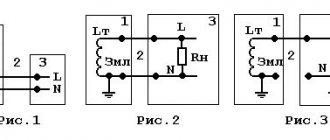
Let's consider several options for electrical connection diagrams of the device for testing:
- Removing characteristics from the “F-N” loop; in the example shown in the figure, the parameters in the C-N circuit are measured.
C-N loop test - Measurement in a loop between one of the phases and the PE conductor.
C-PE loop test - Measurements in CT circuits.
Connecting the device in circuits with protective grounding
- To check the reliability of grounding of electrical equipment, the connection method given below is used.
Testing the reliability of grounding of electrical equipment enclosures
Important! Regardless of the method of connecting the device, you must ensure that the wires are connected securely.
Obtaining information about the network voltage
The device we are considering allows you to measure UH within the range from 0 to 250.0 volts. The phase voltage is displayed on the device display immediately after pressing the power button or after five seconds, after testing (if the control buttons responsible for displaying the results on the screen were not pressed).
Measuring the main characteristics of the F-N loop
The method for measuring ZP in a loop, used in the MZC model range, is based on creating an artificial short circuit using a limiting resistance (10.0 Ohm), which reduces the value of the ISC. After testing, the microprocessor of the device calculates ZP, highlighting reactive and active components. The measurement procedure does not exceed 30.0 ms.
It is characteristic that the device automatically selects the desired range for measuring ZP. When you press the “Z/I” button, the display alternately displays such basic characteristics of the loop as expected short-circuit current (ISC) and total resistance (ZP).
It should be taken into account that when calculating, the microprocessor sets the UH value at 220.0 volts, while the current rated voltage may differ from the calculated one. Therefore, to increase the accuracy of electrical circuit measurements, a correction should be made. For example, with a real UH equal to 240.0 V, the correction to reduce the instrument error will be equal to 1.09 (that is, it is necessary to divide 240 by 220).
The process of measuring loop characteristics is started by the “Start” button.
Important! Tests carried out using instruments from the MZC range are almost guaranteed to trigger the RCD. To avoid this, it is necessary to first bypass the residual current devices. After taking measurements, do not forget to remove the shunt from the RCD.
Reading received information
As mentioned above, tests begin after pressing the “Start” button. After completing the measurements, the characteristics of the “F-N” loop are displayed on the screen, depending on the settings. You can scroll through the information displayed on the display using the “SEL” and “Z/I” buttons.
Please note that the MZC-300 only displays the results of the last measurement. If it is necessary to store the results of all tests in electronic memory, you will need a device with advanced capabilities, for example the MZC-303E device.
MZC-303E device for measuring the characteristics of the F-N loop
Such a device allows you not only to store information about all measurements in electronic memory, but also, if necessary, transfer it to a computer using a USB interface.
General idea of the “phase zero” circuit
Most electricity consumers are powered by networks with a voltage level of up to 1 kV through a three-phase transformer. To ensure safety, they use a solidly grounded neutral. A current may appear in it due to a phase shift in the windings of the transformer, which are connected in a star circuit.
In the event of contact between the linear and neutral or protective wires, a “phase-zero” circuit is formed. This connection leads to the formation of a short circuit. The circuit may contain connecting wires, switching and protective equipment, which is accompanied by the formation of a certain resistance value.
Download
The same article, beautifully laid out and published in the paper magazine “Electrical Technical Market”:
• Short-circuit current: size matters / Article about short-circuit current, published in the magazine Elek.ru, pdf, 4.45 MB, downloaded: 626 times./
Respect and respect if you have read this far and intend to download books on this topic!
You are a serious person! • Shabad_M.A._Calculations_of_relay_protection_and_automation / Shabad M.A. Calculations of relay protection and automation. A good book from 1985, which tells about the design of electrical networks - from the equipment of substations to the selectivity of protective circuit breakers, pdf, 38.87 MB, downloaded: 1071 times./ • Belyaev A.V. Selection of equipment, protection and cables 0.4 kV / Belyaev A.V. Selection of equipment, protection and cables 0.4 kV - a book for the theoretical calculation of short circuit current. St. Petersburg 2008, pdf, 17.39 MB, downloaded: 839 times./ • RD 153-34.0-20.527-98 / Guidelines for calculating short circuit currents and choosing electrical equipment RD 153-34.0-20.527-98. The guidelines are intended for use by energy engineers when performing calculations of short circuit currents (SC) and testing electrical equipment (conductors and electrical apparatus) under the SC mode. MPEI, 1998, pdf, 3.61 MB, downloaded: 791 times./ • Electrical part of power plants and transformer substations / Electrical part of power plants and substations. Detailed description of circuits and calculations with examples. Tutorial. N.V. Kolomiets, Tomsk Polytechnic, 2007, pdf, 1.37 MB, downloaded: 735 times./ • Selection of electrical equipment and calculations of transformer substations / Selection of electrical equipment and calculations of medium and low voltage transformer substations. ABB, educational manual, pdf, 9.16 MB, downloaded: 681 times./ • Kharechko V.N., Kharechko Yu.V. Automatic switches of modular design / Kharechko V.N., Kharechko Yu.V.
Automatic circuit breakers of modular design: Reference manual. The reference manual sets out the requirements of GOST R 50345-99 (IEC 60898-95) for household circuit breakers intended for overcurrent protection, examines the design of circuit breakers, gives characteristics and their classification. Errors are analyzed that are partially corrected in the new version of GOST R 50345-2010, pdf, 7.17 MB, downloaded: 1103 times./ I look forward to questions and comments in the comments!
What to do if the measured short-circuit current is too low?
Let's say we measured it with a device and got the value of the short-circuit current in the socket (as a rule, the measurement is carried out at the most remote point). How can you tell if this current is too low? This is assessed by the criterion of guaranteed operation of the electromagnetic release of the circuit breaker in the measured circuit. It is logical that for this the short-circuit current must be greater than the upper limit of the tripping range. Let me remind you that for characteristic “B” the spread is 3…5 In, for “C” – 5…10 In, for “D” – 10…20 In. To be more precise, let’s turn to the PUE (clause 7.3.139):
7.3.139. In electrical installations up to 1 kV with a solidly grounded neutral, in order to ensure automatic shutdown of the emergency section, the conductivity of the neutral protective conductors must be selected such that, in the event of a short circuit to the housing or neutral protective conductor, a short-circuit current occurs that is at least 4 times greater than the rated current of the fuse link of the nearest fuse and at least 6 times the current of the circuit breaker release, which has an inverse current characteristic.
When protecting networks with automatic circuit breakers that have only an electromagnetic release (without a time delay), you should be guided by the requirements regarding the short-circuit current multiplicity and given in 1.7.79.
As I understand it, the first part of 7.3.139 only talks about the thermal release - its rated current must be at least 6 times less than the short-circuit current. The second part of this paragraph, as well as paragraph 1.7.79, talks about the maximum shutdown time during a short circuit (0.4 s), which must be provided only by an electromagnetic release. At the same time, it is not clearly indicated on the choice of AV taking into account its shutdown characteristics.
Because of this vagueness of the wording, they use the rule set out in PTEEP (checking the operation of protection in a power system with a grounded neutral, clause 28.4), which states that when a short circuit to the neutral protective conductor occurs, the short-circuit current must be at least “1.1 the upper value of the operating current of the instantaneous release.”
That is, for a B10 circuit breaker, the short-circuit current at the end of the line that it protects must be at least 10x5x1.1 = 55 A. If a C25 circuit breaker is installed, the short-circuit current must be at least 25x10x1.1 = 275 A.
If the short-circuit current is less, the permissible response time is by no means guaranteed. What to do? There are two ways out:
- increase the short-circuit current, this requires the cost of laying a new supply line (at least its weakest link),
- reduce the rating of the machine (for example, 25 A to 16) and the letter of the shutdown characteristic (from “C” to “B”) to the detriment of the maximum load power.
Why measure short circuit loop impedance?
Increased network resistance and operation at maximum permissible currents significantly increases the wear and tear of installed equipment and several times increases the likelihood of an accident or its early failure. A short circuit in the electrical circuit due to mechanical damage to the cable insulation or as a result of irreversible processes during natural aging leads to an instant increase in the current value and rapid heating of the conductors. At the same time, the insulation begins to melt and burn. A few seconds before the protection is triggered may be enough to damage and ignite the cable, and then ignite adjacent cables. This situation threatens a fire even if the damaged circuit is subsequently de-energized. Of course, the faster the automatic protection switch operates, the less damage will be caused to electrical equipment and the less risk the life and health of people will be exposed to.
In electrical installations with a grounded neutral, the neutral conductor is connected to the neutral of the step-down transformer, which is combined with the ground loop. In the event of an emergency short circuit from phase to phase, to the body or to the neutral wire, a new electrical circuit appears - the so-called short circuit loop. There are several methods for measuring short circuit loop resistance:
- method of voltage drop in a disconnected circuit;
- method of voltage drop across load resistance;
- short circuit method.
To measure the total resistance (impedance) of a short circuit loop, Sonel uses a technical method of creating an “artificial short circuit”. The MZC series device measures the voltage first without a load, and then under a short-term load with a 10 Ohm resistor (value varies between models) for 30 ms. The short circuit loop impedance contains active and reactive components of resistance and is calculated based on the difference in voltage drops using the formula:
SLC
Figure 1. Active and reactive components of the impedance
The impedance of the short circuit loop should be as small as possible, then the short circuit current in the circuit will be greatest and the protection will operate faster. With an interphase fault, the current in the circuit will be greater than with a single-phase fault. Based on the obtained impedance value, the short circuit current value is calculated. The conditions for proper protection are described by the formula:
SAN
From the above formulas and the diagram, it becomes clear why it is necessary to measure impedance, i.e. TOTAL short circuit loop resistance. Determination of only the resistive component, i.e. active resistance of the circuit, underestimates the actual value, as a result of which the calculation of the operation current will lead to an erroneous result and a false conclusion about the compliance of the protection parameters! In fact, in the case of significant inductive reactance of the short-circuit loop (for example, the winding of a supply transformer, a long cable line), the tripping current calculated based only on the value of the active resistance may be insufficient to provide the required response time of the protection, which will inevitably put the lives of people at risk in emergency situation. Measurements of phase-zero loop resistance in electrical installations up to 1000 V are regulated by clause 28.4 of Table 28 of the Rules for the Technical Operation of Consumer Electrical Installations (PTEEP) when checking the operation of protection in networks with a grounded neutral (TN-C, TN-CS, TN-S) and is carried out once every two years (clause 2.7.16), as well as after each relocation and installation of new electrical equipment before turning it on (clause 2.7.17). The test is carried out by directly measuring the single-phase short circuit current using special instruments or by measuring the impedance of the phase-zero loop with subsequent determination of the short circuit current. The magnitude of the single-phase short circuit current when a short circuit to the housing or neutral working conductor must be at least: 3 times the rated current of the fuse link, 3 times the rated current of the unregulated release or 3 times the setting current of the adjustable release of the circuit breaker with inverse current characteristic. Other parameters for the operation of protective automatic shutdown must comply with the Electrical Installation Rules (PUE ed. 7) clauses 7.3.139 and 1.7.79.
Circuit Resistance Testers
All modern electrical laboratories have meters. The devices reproduce a fake short circuit on a controlled section of the circuit or inside the unit, then immediately measure the resistance of the phase-phase, phase-zero loop (reactive, active, total electrical resistance).
The device instantly calculates the short circuit current without turning off the protection. This is how they check the correctness of the selected nominal value of the machine or fuse. At the same time, they determine the response time of the protection.
Devices help determine:
- values of transition resistances of switching devices (switches, circuit breakers, fuses, contactors, disconnectors, etc.);
- the exact trajectory of the electric current in the event of an accident (through steel pipes, metal water pipes, circuits, other pipelines with iron walls, grounding cable).
The box of devices has holders in the form of magnets, so they can be quickly fixed to steel walls. Paint on metal does not interfere with retention.
Measuring instruments
Given the fact that loop measurement results are in demand, a multimeter is usually used as a measuring instrument. The most commonly used devices are:
- M-417 is a convenient and easy-to-use switch device, which is based on a calibrated bridge-type circuit. Works without the need to remove voltage up to 380 volts.
- MZC-300 is a modern measuring device that has digital processing of measured parameters and is displayed on the display. To measure voltages up to 250 volts, you can use a 10 ohm test resistance.
- IFN-200 is a device operating under voltage up to 250 volts, which can be used as a tester. However, with loop measurements, the range of resistance values is below 1000 Ohms.
It is worth noting that the parametric loop measurement of the phase-zero loop resistance is simple. All that is needed is to attach the probes to the contact points, which must first be cleaned with sandpaper or a file to minimize contact resistance. After this, the equipment is turned on and the result appears on the display.
Features of the circuit breaker
The design of the device and the principles of operation of this protection are described in a separate article. I recommend checking it out.
The circuit breaker is designed to quickly remove voltage from the power circuit in the event of an overload or a short circuit.
Overload mode
The initial protection of the electrical circuit was previously carried out using a fuse, the fuse of which simply burned out and broke the electrical circuit under the thermal influence of the emergency current.
This function remains in the design of the circuit breaker. In it, it is implemented by a thermal release and provides overload protection, removing voltage from the protected area with a time delay. This is necessary to eliminate frequent shutdowns when transient processes occur from various switching circuits.
It is convenient to determine the operating area of the thermal release, as well as its second component, the shutdown electromagnet, using the time-current characteristic, which indicates the dependence of the response time on the magnitude of the emergency current passing through the contacts of the bimetallic plate.
Short circuit mode
When it occurs, the maximum possible power is applied to the circuit, the energy of which can melt metal wires or cause a fire. Therefore, in order to preserve the equipment, it is necessary to perform very fast power removal in thousandths of a second.
This is the task of the second component of circuit breaker protection: current cutoff, which is performed by an electromagnetic release.
Both machine protections operate autonomously, do not depend on each other, and have their own settings and settings. However, they are selected for a specific value of the operating rated current and are designed to ensure its normal passage without unnecessary, false shutdowns.
The principle of selecting a circuit breaker
When determining its technical capabilities, the following are taken into account:
- the value of the rated current in the network, which is significantly influenced by the condition of the electrical wiring and the loads connected to it;
- permissible overload mode;
- disconnecting capacities of possible emergency modes.
The algorithm for selecting a circuit breaker based on rated current, taking into account the features of the power supply circuit, is shown in the diagram.
It allows you to make a preliminary calculation of the necessary parameters of the circuit breaker and select its protective characteristics.
To carry out such a calculation, you can also use the Electric 7-8 computer program.
Is high short-circuit current good or bad?
As I showed in the graph earlier, the further the fault location is from the power source, the lower the short circuit current will be because the line resistance will be greater. High short-circuit current usually occurs in those places of the power network that are located closest to the substation, and cable lines have a large cross-section of wires. In supply networks with a voltage of 0.4 kV, short-circuit currents of more than 6 kA are considered relatively high, and short-circuit currents above 15 kA are practically never encountered. So what we have:
Disadvantages of low short circuit current
- large voltage drop under sufficiently powerful load;
- As a rule, low voltage on electrical appliances. In this case, the stabilizer will not always help;
- instability of voltage on electrical appliances depending on the time of day or season. I conducted an investigation according to the voltage standards and its tolerances;
- high (up to infinity) response time of circuit breakers during a ground fault (only the thermal release works);
- the need to install circuit breakers with a shutdown characteristic of “B” in order to more likely trigger the electromagnetic release during a short circuit. This controversial issue is discussed in my article on Zen Why install machines with the “B” characteristic;
- mandatory installation of an RCD - in addition to its “main” responsibilities (switching off power at high leakage current, as well as to protect people during direct and indirect contact), the RCD performs the function of protection against ground faults (PUE 1.7.59, 7.1.72 ).
Pros of low short circuit current
- you can install cheap circuit breakers with a low rated maximum breaking capacity (Icn = 4500 A);
- It is relatively easy to ensure selectivity between the input and subordinate automata. But we need to calculate and measure the exact value of the short-circuit current,
- low starting current of electric motors and other inertial loads. Article What is inrush current, how to measure and calculate it.
Disadvantages of high short circuit current
- impossibility of ensuring selectivity between higher and lower-level machines. The solution is to install a switch or a time-selective circuit breaker;
- the need to install an AV with a high rated maximum breaking capacity (Icn = 6000, 10000 A, etc.). The breaking capacity must be higher than the short-circuit current at the beginning of the protected section (PUE clause 3.1.3);
- large negative consequences when a short circuit occurs.
Pros of high short circuit current
- it is easy to guarantee stable voltage at the load and the quality of electricity in general;
- there is a prospect of connecting new consumers and increasing the load;
- guaranteed line shutdown in case of short circuit.
Selectivity of circuit breakers and RCDs is a separate big topic, and there are plans.
Summarizing the pros and cons, we can say that the value of the short-circuit current is a double-edged sword. In the domestic sector, the short-circuit current is often low, and they try to increase it by laying new lines with a high cross-section of wires and installing new transformer substations. In serious energy, on the contrary, methods are used to reduce short-circuit current.
Loop measurement order: zero
Measurement of the resistance of the phase-zero circuit can be carried out with or without removing the voltage. In most cases, they are performed without relieving tension.
Measurements without stress relief can be performed:
- In additional load mode. The phase-to-zero circuit is closed through an additional load. In this case, the voltage drop and current passing through the load are measured and the loop resistance is calculated.
- In short circuit mode. The closing time is a few milliseconds. This method is implemented in most modern devices.
Measurement technique
Measuring loop characteristics depends on the technique chosen and the instrument used. The most commonly used devices are those that directly measure the resistance of the phase-zero loop with further calculation of the predicted short-circuit current. For example, using IFN-200.
The device is connected to the operating circuit at the most distant point from the input panel. If it is not possible to determine the farthest point of the line, measurements are taken at all or several points of this line. Next, using the obtained values, the current of a possible short circuit is compared with the characteristics of the protection device.
Examples of calculations
Two methods are considered as examples of such measurements.
Effect of voltage drop on the controlled section of the power circuit
When describing this method, it is important to pay attention to the difficulties of its practical implementation. This is because several steps are required to obtain the final result. First you will have to measure the network parameters in two modes: with the load disconnected and connected
First you will have to measure the network parameters in two modes: with the load disconnected and connected
In each of these cases, resistance is measured by taking current and voltage readings. Next, it is calculated using classical formulas arising from Ohm’s law (Zп=U/I)
First you will have to measure the network parameters in two modes: with the load disconnected and connected. In each of these cases, resistance is measured by taking current and voltage readings. Next, it is calculated using classical formulas resulting from Ohm’s law (Zп=U/I).
In the numerator of this formula, U represents the difference between two voltages - when the load is on and when the load is off (U1 and U2). The current is taken into account only for the first case. To obtain correct results, the difference between U1 and U2 must be large enough.
The impedance takes into account the impedance of the transformer coil (it is summed with the result obtained).
Application of an independent power supply
This approach involves determining the parameter of interest to specialists using an independent source of supply voltage. When carrying it out, you will need to take into account the following important points:
- During the measurement process, the primary winding of the station supply transformer is short-circuited.
- From an independent source, the supply voltage is supplied directly to the short-circuit zone.
- Phase-zero resistance is calculated using the already familiar formula Zп=U/I, where: Zп is the value of the desired parameter in Ohms, U is the measured test voltage in Volts, I is the value of the measuring current in Amperes.
All the methods considered do not claim absolute accuracy of the results obtained from them. They provide only an approximate estimate of the impedance value of the phase-zero loop. This nature of it is explained by the impossibility, within the framework of the proposed methods, of measuring inductive and capacitive losses, which are always present in power circuits with distributed parameters. If it is necessary to take into account the vector nature of the measured quantities (phase shifts, in particular), special corrections will have to be introduced.