Accurate method for determining single-phase fault current
1.1 The exact method for determining the single-phase short circuit current is presented in GOST 28249-93, formula 24, and is calculated using the formula:
Using this method, it is possible to determine with a high degree of accuracy short-circuit currents with known resistances of the positive, negative and zero sequence of the phase-zero circuit.
Unfortunately, in practice, this method is not always possible to use, due to the lack of reference data on positive, negative and zero sequence resistances for cables with aluminum and copper conductors, taking into account the methods of laying phase and neutral conductors.
Calculation of short circuit current in a 0.4 kV network
Introduction
In accordance with clause 3.1.8. PUE electrical networks must have protection against short-circuit currents, ensuring the shortest possible shutdown time; it is indicated that the protection must be checked in relation to the smallest rated short-circuit current (hereinafter referred to as the short-circuit current) to the rated current of the fuse link or circuit breaker release. (For more information about choosing protection against short-circuit currents, read the article: Calculation of the electrical network and selection of protection devices)
Approximate method for determining single-phase short-circuit current
2.1 Approximate method for determining single-phase short-circuit current at high power of the supply power system (Xc
Where:
- Uph – phase voltage of the network, V;
- Zt – total resistance of the transformer to the current of a single-phase short circuit to the body, Ohm;
- Zpt – total resistance of the phase-zero loop from the transformer to the short-circuit point, Ohm.
2.2 If the supply power system has limited power, then the single-phase short circuit current is determined by formula 2-26 [L3, p. 39]:
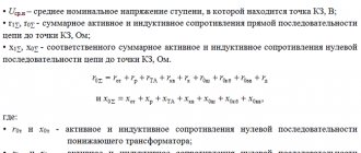
2.3 The value of Z∑ is determined according to table 2.9 or can be determined using formula 2-25 [L3, p. 39]:
where: x1t and r1t; x2t and r2t; x0t and r0t - inductive and active resistance of the transformer to direct, negative and zero sequence currents, mOhm. Accepted according to table 2.4 [L3, p. 29].
The value of Zt/3 for various transformers with a secondary voltage of 400/230 V can be taken from tables 2, 3, 4 [L1, p 6.7].
The contact resistances of buses, devices, and current transformers are not taken into account in this method, since the arithmetic sum of Zt/3 and Zpt creates a certain margin.
2.4 Transformer impedance Zt is determined by formula 2-24 [L3, p. 39]:
2.5 The impedance of the phase-zero loop is determined by formula 2-27 [L3, p. 40]:
Where:
- Zpt.ud. – the total resistivity of the phase-zero loop for each section from the transformer to the short-circuit location is determined according to tables 2.10 - 2.14 [L3, p. 41,42] or according to tables [L2], mOhm/m;
- l – length of the section, m.
Below are reference tables with the resistivity values of the phase-zero loop for various cables and busbars according to [L3, pp. 41,42].
Reference tables 7, 10 with active resistance values of copper and aluminum wires and cables [L1, p. 6, 14].
Reference tables 11, 12, 13 with the values of the total calculated resistance of the phase-zero circuit for 3 (4) - core cables with different insulation and at a core temperature of +65 (+80) C [L1, p. 15, 16].
In practice, according to [L1, p. 5], it is recommended to use an approximate method for determining the single-phase short-circuit current. With this method, the permissible error in calculating the single-phase short-circuit current with inaccurate initial data is on average equal to 10% towards the margin; 18-20% - with the Y/Y0 transformer connection scheme, when the active load predominates and the 4th core or cable sheath is used for grounding; 10-12% - when using steel pipes to neutralize electrical wiring.
From the above, it follows that when using this method, a certain margin is created in the calculation, which guarantees the operation of the protective device, in accordance with the requirements of the PUE.
1. Recommendations for calculating the resistance of the phase-zero circuit. Glavelektromontazh. 1986 2. GOST 28249-93 – Calculation methods in alternating current electrical installations with voltage up to 1 kV. 3. Belyaev A.V. Selection of equipment, protection and cables in a 0.4 kV network. Tutorial. 2008
Share on social networks
If you have found the answer to your question and you want to thank the author of the article for his work, you can use the platform for transferring funds “WebMoney Funding”.
This project is supported and developed exclusively with funds from voluntary donations.
By showing loyalty to the site, you can transfer any amount of money, thereby you will help improve this site, increase the regularity of new interesting articles and pay for regular expenses, such as: payment for hosting, domain name, SSL certificate, salary to our authors.
This article will focus on calculating the current cutoff for electric motors with voltages above 1.
Self-starting currents of electric motors are calculated to select the maximum operating current.
The choice of voltage transformer power comes down to calculating the load for the main load.
In this article I would like to talk about sensitivity testing for overcurrent protection (OCP).
In this example, we will consider the calculation of protection settings for a 6 kV cell supplying a smooth reactor device.
By sending a message, you consent to the collection and processing of personal data. Privacy Policy.
TIME-CURRENT CHARACTERISTICS OF CIRCUIT BREAKERS
According to GOST R 50345-99, clause 3.5.17, this is the lowest current value at which the circuit breaker will trip (turn off) without a time delay, i.e. its electromagnetic protection.
The same GOST R 50345-99, clause 5.3.5., states that there are three standard characteristics (types of instantaneous release):
B - from 3·In to 5·In C - from 5·In to 10·In D - from 10·In to 20·In (available from 10·In to 50·In) In – rated current of the circuit breaker.
Let's consider each type of characteristic using the example of a modular circuit breaker BA47-29.
Time-current characteristic type B
The graph (curve) shows the dependence of the circuit breaker shutdown time on the current flowing through it. The X axis is the multiple of the current in the circuit to the rated current of the machine (I/In). Y-axis—response time, in seconds.
The graph is divided by two lines, which determine the spread of the response time of the thermal and electromagnetic protections of the machine. The lower line is the hot state of the machine (after operation), and the upper line is the cold state.
The characteristics of almost all machines are displayed at a temperature of +30°C.
On the presented time-current characteristics (abbreviated as VTC), the dotted line is the upper limit (limit) for machines with a rated current of less than 32 (A).
The graph shows:
1. If a current equal to 3 In passes through the circuit breaker, then it should turn off in a time of 0.02 seconds in a hot state, up to 35 seconds in a cold state (for machines less than 32A) and up to 80 seconds in a cold state
2. If a current equal to 5·In passes through the circuit breaker, then it should turn off in 0.01 seconds when hot or in 0.04 seconds when cold (for machines over 32A).
Circuit breakers with characteristic B are used mainly to protect consumers with predominantly active loads, for example, electric ovens, electric heaters, lighting circuits.
True, for some reason their quantity in stores is always limited, because... a common type is characteristic C. And who decided that? It is quite advisable to install type B on group circuit breakers for lighting and sockets, and type C on the input circuit breaker. This way, selectivity will be maintained, and in the event of a short circuit somewhere in the line, the input circuit breaker will not turn off and “extinguish” the entire apartment.
Time-current characteristic type C
Here is her schedule:
1. If a current equal to 5 In passes through the circuit breaker, then it should turn off in a time of 0.02 seconds in a hot state, up to 11 seconds in a cold state (for machines less than 32A) and up to 25 seconds in a cold state (for machines more than 32A).
2. If a current equal to 10·In passes through the circuit breaker, it should turn off in 0.01 seconds when hot or 0.03 seconds when cold.
Circuit breakers with characteristic C are mainly used to protect transformers and motors with low starting currents. They can also be used to power lighting circuits. They have found quite wide distribution in the housing stock, although I expressed my opinion about this a little higher.
Time-current characteristic type D
Schedule:
1. If a current equal to 10 In passes through the circuit breaker, then it should turn off in a time of 0.02 seconds in a hot state, up to 3 seconds in a cold state (for machines less than 32A) and up to 7 seconds in a cold state (for machines more than 32A).
2. If a current equal to 20 In passes through the circuit breaker, it should turn off in 0.009 seconds when hot or 0.02 seconds when cold.
Circuit breakers with characteristic D are used mainly to protect electric motors with frequent starts or significant starting currents (heavy starting).
What is a phase-zero loop in simple terms - measurement technique
Electrical appliances should work flawlessly if the electrical circuit complies with all norms and standards. But changes occur in power lines, which over time affect the technical parameters of the network. In this regard, it is necessary to periodically measure indicators and prevent power supply. As a rule, they check the performance of automatic machines, RCDs, as well as the parameters of the phase-zero loop. Below are details about the measurements, which instruments to use and how to analyze the results.
What is meant by the term phase-zero loop?
According to the rules of the PUE, in power substations with voltages up to 1000V with a solidly grounded neutral, it is necessary to regularly measure the resistance of the phase-zero loop. The electricity supplied to consumers comes from the output windings of a three-phase transformer, which is connected in a star circuit. As a result of natural phase imbalance, current may flow through the neutral circuit, therefore, to prevent the problem, phase-zero is measured.
A phase-zero loop is formed if you connect a phase wire to a neutral or protective conductor. As a result, a circuit is created with its own resistance through which electric current moves. In practice, the number of elements in a loop can be much larger and include circuit breakers, terminals and other connecting devices. If necessary, you can calculate the resistance manually, but the method has several disadvantages:
- it is difficult to take into account the parameters of all switching elements, including switches, automatic machines, circuit breakers, which could change during the operation of the network;
- it is impossible to calculate the impact of an emergency on resistance.
The most reliable way is to measure the value using a verified device, which takes into account all errors and shows the correct result. But before starting the measurement, it is necessary to do some preparatory work.
What is a short circuit?
Many people know such a stable expression - “short circuit”. In addition to the name of a famous blockbuster from the 90s, the average person associates these words with a common cause of fires. There are many myths and cliches floating around on this topic. I decided to figure out what was what and why all this was needed.
A short circuit (SC) is a mode of operation of the electrical network, or a phenomenon in which the maximum possible current flows in the circuit at the point of the circuit. This event is difficult to predict and emergency, and the sooner it stops, the better. When a short circuit occurs, all the energy of the power source is spent only on heating the wires. In addition, dynamic (mechanical) consequences are possible. This process is usually very fleeting and explosive, since the thermal energy released is colossal. If you do not stop this disgrace as quickly as possible (we will look into how this is done below), then short circuit can lead to large material and human losses.
The shutdown time of household circuit breakers during a ground fault is less than 0.1 s. If the shutdown occurs through devices that respond to differential current (RCD, RCBO), the response time will be less than 0.04 s.
A short circuit can occur between any points in an electrical circuit that have different potentials. Here's what it looks like in three-phase form:
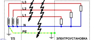
Short circuits in the power supply system with the TN-S grounding system
The figure conventionally shows the secondary winding of a step-down transformer installed in a transformer substation (TS), a five-wire power line and a three-phase electrical installation. The electrical installation can be a private or apartment building, or maybe something industrial.
Closures can come in different forms:
- two- and three-phase (phase-to-phase),
- one-, two- or three-phase to neutral N or protective PE conductor.
If we consider the safest grounding system TN-S with a solidly grounded neutral of the transformer, then most often (in practice - about 90%) a single-phase short circuit occurs between the phase wire and the neutral N (or the protective conductor PE). Therefore, further we will consider a simpler, single-phase option:
Short circuit to neutral and protective conductors
I recommend my article: How three-phase voltage differs from single-phase. And linear from phase.
A short circuit can happen anywhere - even near a transformer substation (TS) due to the inattention of an excavator operator, or in an apartment because of a cat that dropped a Christmas tree. In any case, the protection must work clearly, minimizing the consequences of a short circuit.
By the way, our cat once dropped our Christmas tree. They threw her out of the 5th floor.
Why check the resistance of the phase-zero loop?
Checking is necessary for preventive purposes, as well as to ensure the correct operation of protective devices, including circuit breakers, RCDs and automatic circuit breakers. For example, a common problem is when a kettle or other electrical appliance is plugged into the outlet, and the machine turns off the load.
Important! High resistance causes false operation of the protection, heating of the cables and fire.
The reason may lie in external factors that are difficult to influence, as well as inconsistency between the protection rating and the current parameters. But in most cases, it's a matter of internal problems. The most common reasons for the automatic operation of machines are:
- loose contact at the terminals;
- current does not match the characteristics of the wire;
- reduction in wire resistance due to obsolescence.
The use of measurements allows you to obtain detailed data about network parameters, including transition resistances, as well as the influence of circuit elements on its performance. In other words, the phase-zero loop is used for the prevention of protective devices and the correct restoration of their functions.
Knowing the parameters of the circuit breaker for a specific line, after taking a measurement, you can say with confidence whether the circuit breaker will be able to operate in the event of a short circuit or whether the wires will start to burn .
Frequency of measurements
Reliable operation of the electrical network and all household appliances is possible only if all parameters comply with the standards. To ensure the desired characteristics, periodic testing of the phase-zero loop is required. Measurements are taken in the following situations:
- After commissioning of equipment, repair work, modernization or network maintenance.
- Upon request from service companies.
- At the request of the electricity consumer.
Reference! The frequency of inspection in aggressive conditions is at least once every 2 years.
The main task of measurements is to protect electrical equipment, as well as power lines from heavy loads. As a result of the increase in resistance, the cable begins to become very hot, which leads to overheating, tripping of circuit breakers and fires. The value is influenced by many factors, including environmental aggressiveness, temperature, humidity, etc.
What devices are used?
To measure phase parameters, special verified devices are used. The devices differ in measurement methods, as well as design features. The following measuring instruments are most popular among electricians:
- M-417. A device proven by experience and time, designed to measure resistance without disconnecting the power source. Features include ease of use, dimensions and digital display. The device is used in any AC networks with a voltage of 380V and a permissible deviation of 10%. M-417 automatically opens the circuit for an interval of up to 0.3 seconds to take measurements.
- MZC-300. Modern equipment for checking the condition of switching elements. The measurement technique is described in GOST 50571.16-99 and consists of simulating a short circuit. The device operates in networks with a voltage of 180-250V and records the result in 0.3 seconds. For greater operational reliability, low or high voltage indicators are provided, as well as overheating protection.
- IFN-200. A microprocessor-controlled device for measuring the resistance of the phase-zero loop without turning off the power. The reliable device guarantees the accuracy of the result with an error of up to 3%. It is used in networks with voltages from 30V to 280V. Additional advantages include measuring short-circuit current, voltage and phase angle. The INF-200 device also remembers the results of the last 35 measurements.
Important! The accuracy of measurement results depends not only on the quality of the device, but also on compliance with the rules for performing the chosen technique.
How is loop resistance measured, phase zero?
Measuring loop characteristics depends on the chosen technique and instrument. There are three main methods:
- Short circuit. The device is connected to the operating circuit at the most distant point from the input panel. To obtain the required indicators, the device produces a short circuit and measures the short-circuit current and the operating time of the circuit breakers. Based on the data, parameters are automatically calculated.
- Voltage drop. For this method, you need to disconnect the network load and connect the reference resistance. The test is carried out using a device that processes the results obtained. The method is considered one of the safest.
- Ammeter-voltmeter method. A rather complex option, which is carried out with the voltage removed, and also uses a step-down transformer. By connecting the phase wire to the electrical installation, they measure the parameters and calculate the characteristics using formulas.
Brief description of MZC-300
Let's look at the appearance and main elements of the MZC-300 meter.
- Information display. A full description of its fields can be found in the user manual.
- "Start" button. Starts the following measurement processes:
- ZP, recall, is the total resistance of the F-N circuit.
- ISC – expected short-circuit current.
- Active resistance is necessary for calibrating the device.
The start of each measurement is accompanied by a characteristic sound signal.
- SEL button. Serves for sequential display of all loop characteristics obtained as a result of the last measurement on the information display. In particular, the following information is displayed:
- ZP parameters.
- Expected IKZ.
- Level of active and reactive resistance (R and X).
- Phase angle ϕ.
- Z/I button. At the end of the test, switches the display of characteristics between the expected ISC and ZP.
- Button to disable/enable the measuring device. If, when starting the device, you press “SEL” simultaneously with this button, the meter will go into auto-calibration mode. Its detailed description can be found in the user manual.
- Connector for connecting a probe in contact with the working zero, PE or PEN conductor. The corresponding designation is marked on the body of the device.
- Connector for a probe connected to one of the phase wires. As a rule, marked with the letter “L”.
- Like the i connector, unlike the test lead sockets, it is used only in automatic calibration mode. On the device body they are designated as “K1” and “K2”.
Useful tips Connection diagrams Principles of operation of devices Main concepts Meters from Energomer Precautions Incandescent lamps Video instructions for the master Testing with a multimeter