To ensure proper operation of household appliances connected to the electrical network and ensure their safe operation, all connections must be made in accordance with the PUE. In electrical engineering, errors are not allowed; if the equipment is connected incorrectly, there is a risk that they will simply fail ahead of schedule, which can cause a malfunction of the entire system.
In this article we will look at the consequences of an incorrect connection and the correct procedure to avoid unforeseen situations.
Consequences of electricians' mistakes Source encom74.ru
What is a short circuit?
Many people know such a stable expression - “short circuit”. In addition to the name of a famous blockbuster from the 90s, the average person associates these words with a common cause of fires. There are many myths and cliches floating around on this topic. I decided to figure out what was what and why all this was needed.
A short circuit (SC) is a mode of operation of the electrical network, or a phenomenon in which the maximum possible current flows in the circuit at the point of the circuit. This event is difficult to predict and emergency, and the sooner it stops, the better. When a short circuit occurs, all the energy of the power source is spent only on heating the wires. In addition, dynamic (mechanical) consequences are possible. This process is usually very fleeting and explosive, since the thermal energy released is colossal. If you do not stop this disgrace as quickly as possible (we will look into how this is done below), then short circuit can lead to large material and human losses.
The shutdown time of household circuit breakers during a ground fault must be less than 0.4 s (PUE 1.7.79, 7.1.72). If the speed is not ensured due to low short-circuit current, shutdown should occur through devices that respond to differential current (RCD, RCBO), the response time will be (according to GOST) less than 0.04 s.
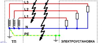
A short circuit can occur between any points in an electrical circuit that have different potentials. Here's what it looks like in three-phase form:
Short circuits in the power supply system with the TN-S grounding system. Who will see the error in the diagram?
The figure conventionally shows the secondary winding of a step-down transformer installed in a transformer substation (TS), a five-wire power line and a three-phase electrical installation. The electrical installation can be a private or apartment building, or maybe something industrial.
Closures can come in different forms:
- two- and three-phase (phase-to-phase),
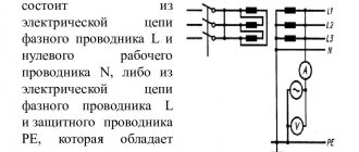
- one-, two- or three-phase to neutral N or protective PE conductor.
If we consider the safest grounding system TN-S with a solidly grounded neutral of the transformer, then most often (in practice - about 90%) a single-phase short circuit occurs between the phase wire and the neutral N (or the protective conductor PE). Therefore, further we will consider a simpler, single-phase option:
Short circuit to neutral and protective conductors
I recommend my article: How three-phase voltage differs from single-phase. And linear from phase.
A short circuit can happen anywhere - even near a transformer substation (TS) due to the inattention of an excavator operator, or in an apartment because of a cat that dropped a Christmas tree. In any case, the protection must work clearly, minimizing the consequences of a short circuit.
By the way, our cat once dropped our Christmas tree. They threw her out of the 5th floor.
Video description
If the outlet has 2 phases.
It is important to determine the phase: according to the PUE, voltage should not occur on the chandelier socket if the lamp is turned off. Otherwise, the process of replacing an ordinary light bulb will become a dangerous phenomenon that can kill a person. According to the standards, the phase wire is located on the left of the socket. Accordingly, the right one will be zero. The remaining wire with yellow-green insulation should be ground. In rare network designs, this may be a 220-volt backup conductor.
Lived in yellow insulation - earth Source leaba.ru
In a double switch, the input and output contacts are scattered on different sides. One is located at the bottom, the other at the top. The one located on the side, where only one contact comes, is the phase. The other two are working zero plus protective zero. All this will be correct under one condition: the electrical wiring in the apartment is laid correctly. In old houses, the layouts may not be the same, but done the other way around.
It is impossible to determine the phase of a single-key switch, since the contacts are located on one side. You can ring the cartridge using a tester, but by doing such a measurement, you violate safety regulations (TB). The meter may break, so this method is not recommended for everyday use. It is better to try to measure the voltage: if the device shows 230 volts between 2 points, then the phase goes to the switch, zero - to the cartridge.
Causes of short circuit
A short circuit can occur for various reasons, the main one of which is a violation of the insulation or the relative position of live parts.
Very often, human or natural factors are to blame for the occurrence of short circuits. An example that women will appreciate (a miracle if they read this article) - due to constant kinks, the insulation deteriorates, and at one “wonderful” moment the hair dryer or iron “bangs” at the input or near the plug.
Another example is that due to mechanical failure or external influence, current-carrying parts for some reason end up too close to each other, even to the point of complete contact. This can happen due to natural phenomena (a tree fell on the wires), shocks, or falling electrical appliances.
Well, a classic example is a short circuit due to interference in the electrical wiring of home “jacks of all trades”. According to the laws of the genre, after this incident the master’s hair must stand on end and his face must be black. Such pictures don’t make me laugh – everything happens differently.
Purpose of RCD
Everyone knows that over time, wire insulation ages. Damage may occur, and the contacts connecting live parts gradually weaken. These factors ultimately lead to current leakage, which causes sparking and further fire. Often, people may accidentally touch such emergency phase wires that are under voltage. In this situation, electric shock poses a serious danger.
Residual current devices must respond to even minor short-term current leaks. This is their main difference from circuit breakers, which operate only during overloads and short circuits. Automatic machines have a very high time-current response characteristic, while an RCD operates almost instantly, in the presence of even the most minimal leakage current.
The main purpose of the RCD is to protect people from possible electric shocks, as well as to prevent dangerous current leaks.
How to avoid short circuit?
It is clear that it is impossible to completely avoid this unpleasant phenomenon - there is a great element of chance here. However, we are able to significantly reduce the risk of short circuits. And here regular inspection and maintenance of electrical networks becomes of enormous importance.
Examples of preventive measures:
- cleaning live parts, contacts and insulators from dust and dirt,
- checking moisture protection,
- checking the integrity of installation and installation,
- fencing and additional protection of dangerous areas,
- hanging and sticking warning signs and inscriptions,
- checking and pulling contacts,
- pruning trees and eliminating other hazardous factors.
What do you think are the necessary preventive measures to protect against short circuits in the photo below?
Drainpipe, electrical panels and corrugation that goes under the tiles. Installation in the old part of Batumi
Serious organizations regularly check cables and contacts with a thermal imager, as well as measure insulation resistance and test insulation with high voltage voltage.
Short circuit and overload
What is the difference between these two phenomena - short circuit and overload?
In an electrical circuit, 4 fundamentally different modes can be distinguished, which differ in current consumption:
- Idle mode. The current is zero, the voltage is rated, there are no losses on the wires. An outlet to which nothing is connected acts as a voltage source in idle mode.
- Nominal mode. Otherwise - normal mode, when the load power does not exceed the design one. In this mode, everything is fine, we are quietly enjoying the benefit of electrification of the country. If there is a voltage drop, it will be insignificant - a few percent.
- Overload mode. In this mode, the current can slightly (tens of percent) or several times (hundreds of percent) exceed the rated current. Overload can occur due to partial deterioration of insulation, excess of the total power of connected consumers, or due to a malfunction inside a separate electrical appliance (for example, an interturn short circuit or a jammed electric motor, or a short circuit inside the heating element).
- Short circuit mode. This is the most severe, destructive mode with large heat release. The current at the fault point is the maximum possible for the given conditions. Other side effects of a short circuit are a decrease in voltage for other consumers (how new German refrigerators burned out in the regional Magnit warehouse due to low voltage) and phase asymmetry (what phase asymmetry (misalignment) leads to and how to protect against it).
That is, an overload differs from a short circuit in the magnitude of the overcurrent. During a short circuit, the current becomes the maximum possible at a given point in the circuit, and during an overload, the current value is greater than the rated value, but less than the short circuit current.
Any currents higher than the rated current are called overcurrent .
Due to an overload, a short circuit can easily occur - the wires heat up, the insulation melts, and so on, with all the ensuing, shooting and exploding consequences.
Do not confuse overload, short circuit and sparking (arc breakdown). If the first two concepts differ in the value of the overcurrent, then in the event of a sequential arc breakdown (for example, the tightening of a terminal in a socket is loose), the effective value of the current can be quite insignificant (units of amperes), which will not trigger either the circuit breaker or the RCD. Only an anti-sparking device (against arc breakdown), which is still relatively rare, can save the situation from a fire.
I have several articles on such devices on my blog, here is the last one for today.
Determination methods
Let's look at ways to determine the neutral and grounding conductors, from very simple to more complex.
The circuit has diff current protection. If the entire object or branch under study is equipped with differential current protection - a differential current device or an RCD, the task is greatly simplified. You need to connect a control device, for example a lamp with conductors, to the phase and to one of the conductors being tested. If the differential protection does not work, then the lamp is connected to the working zero. If an RCD is triggered when a lamp is connected, you connect it to phase and ground. Everything is quite simple and at the same time check the residual current device in practice.
Before performing such a test, you need to make sure that the diff protection is working by pressing the “test” button on the protective device. It should be noted that the method will work provided that the current through the lamp exceeds the rated differential current of the device. That is, when using an incandescent lamp (an energy-saving lamp is not suitable), an RCD with a leakage current of 10-30 mA will trip. The introductory RCD for a 300 mA leak may not work; for a reliable test, you need to take a more powerful device.
Comparison with grounding contacts of sockets. This method will work if there is a two-pole circuit breaker at the input that opens the working zero and there are grounded sockets in the room. The input machine should be turned off, thereby we will open any connection between zero and ground. If possible, unplug all appliances from electrical outlets.
Next, you should “ring” with a multimeter in resistance measurement mode the grounding contact of one of the sockets with the contacts being tested. When connected to the neutral wire, the multimeter should show a high resistance; with a ground contact at an unknown point with the ground of the socket, the resistance is almost zero.
In this way, you can at the same time check the correctness of the connected sockets: when the input two-pole circuit breaker is turned off, the neutral and ground contacts should not ring. Well, this is provided that the wiring is initially in good working order and installed correctly.
Climb into the shield. If it is not possible to implement the previous methods, you will have to go into the “stuffing” of the electrical panel. I think there is no point in reminding about safety precautions here: no one has canceled it. In fact, the method is quite simple: you need to find the neutral conductor going into the room and disconnect it from the switchboard terminals. Then ring with the contacts being tested: the one with whom the call will be made is the neutral conductor.
In the case of a shield, difficulties may well arise when even in the shield it is difficult to distinguish zero from grounding. In this case, you will need current clamps. You need to turn on the voltage and load in the room, and use clamps to examine unknown conductors in the shield - where there is current, there is a working zero. Please note: the method only works if you know for sure that one of the conductors is zero and the other is ground.
All of the above methods work with both grounding and grounding.
Determine the contacts when connecting the electric stove. Sometimes it becomes necessary to replace an electric stove socket, but the wiring is from Soviet times or the early 90s, one color. To correctly determine whether an electric stove is zero, a condition is necessary - a two-pole circuit breaker in the input switchboard, which disconnects both phase and zero from the entire apartment.
So, with the power turned on, we determine the phase on the terminals under study for the future socket - we mark this contact and throw it aside, then we don’t need it. Then you need to determine the zero in any socket in the apartment - since the wiring is Soviet, there is no ground there, so the zero will be the terminal on which the indicator screwdriver does not light up.
Now we turn off the power to the entire apartment and use a multimeter to dial the zero of a regular outlet with the two remaining contacts for the electric stove. The contact that rings with the zero of the socket is working, and the one that does not ring is zero (ground). If both contacts ring, you need to look for errors in the electrical wiring. When organizing grounding in Soviet times, it was connected to the “PEN” terminal without any switching devices.
What determines the voltage and current during a short circuit?
Above I said that a short circuit can occur at any point on the line. Let's figure out how the current and voltage will depend on the location of the short circuit.
A short circuit is a physical phenomenon. Short circuit current is a parameter of the power supply network, measured in amperes or kiloamperes (kA).
The German physicist Ohm has taught us since school years that voltage and current are determined through the resistance of the circuit:
Short circuit current, like any current, is also calculated according to Ohm's law and depends on the voltage and resistance in a given section of the circuit. Since the resistance of wires in real life is not only what the multimeter shows, but also the inductive component, we will write Ohm’s law for short-circuit current in a more general form:
In the numerator U is the rated voltage in the network (no-load voltage at the output of the transformer at the transformer substation). The number that is obtained in the calculations in the denominator is the total resistance of the circuit Z, on which the short-circuit current depends. Let's consider a single-phase power supply circuit for an apartment and a real case of a short circuit with a shorted hair dryer:
Short circuit at the end of the supply line (minimum short-circuit current)
The diagram shows the impedances of various sections of the supply network:
- Z1 – internal resistance of the transformer at the substation, taking into account the recalculated resistance of the high-voltage part,
- Z2 – cable line from the transformer substation to the distribution point (DP) of the apartment building,
- Z3 – cable line from the distribution point to the apartment panel,
- Z4 – cable from the panel to the socket in one of the rooms,
- Z5 – carrying from an outlet to a closed hair dryer.
The hair dryer burned out and caused a short circuit
Here's what a voltage level graph might look like in different areas - from the terminals of a transformer at a substation to a shorted hair dryer plug:
Voltage drop to zero as a result of a short circuit at the end of the line
The voltage drop is accompanied by the release of heat in all parts of the supply line. In powerful sections with a large cross-section of wires, the share of the “indoor” short-circuit current is negligible, so the drop there is small (sections with resistance Z1, Z2).
Article about voltage drop. Calculation in low-voltage circuits and in DC circuits, without taking into account the reactive component.
In connection with the voltage drop as a result of a short circuit, it can be noted that this will be noticeable on parallel loads connected, for example, to the same RP. In the event of a short circuit or severe overload of one of the consumers, the light bulbs in neighboring houses and entrances will begin to burn dimmer. Has it happened?
And here’s what the change in short-circuit current from the source to the fault point might look like:
Decrease in current when moving away from the power source
The typical value of the short-circuit current at the terminals of a transformer with a power of up to 1000 kVA, which is used to power urban consumers, is about 10 kA. But in the sockets of our apartments, the short-circuit current can be about 1000 A. In the private sector and rural areas, the value of the short-circuit current can be much less - up to 100 A.
Transformer at a 10000/0.4 kV substation with a power of 1000 kVA with a solidly grounded neutral of the secondary winding. This is roughly what our “districts, neighborhoods, residential areas” are powered by.
A little theory.
Without going into technical details, we can say that a single-phase electrical network is a method of transmitting electric current when alternating current flows to the consumer (load) through one wire, and returns from the consumer through another wire.
Let's take, for example, a closed
an electrical circuit consisting of an alternating voltage source, two wires and an incandescent lamp.
From the voltage source to the lamp, current flows through one wire and, having passed through the filament of the lamp, making it hot, the current returns to the voltage source through another wire. So, the wire through which current flows to the lamp is called phase
or simply
phase
(
L
), and the wire through which current returns from the lamp is called
zero
or simply
zero
(
N
).
When, for example, a phase wire breaks, the circuit opens, the flow of current stops and the lamp goes out. In this case, the section of the phase wire from the voltage source to the break point will be under current or phase voltage
(phase). The rest of the phase and neutral wires will be de-energized.
Estimated value of short-circuit current
How to find out the short-circuit current? It would seem – what’s difficult? Substitute the values into the formula and count!
However, the full calculation of the short-circuit current is very complex, and it can be devoted to a coursework, or even a diploma project. In this case, you need to know a lot of initial data (for example, the power of the transformer at the TP and the inductive reactance of all sections of cable lines), and still the result will be theoretical, not taking into account reality - for example, contact resistances. It is also important to take into account that during a short circuit there are two current components: aperiodic (the shock part, the most powerful and unpredictable), which acts only at the initial moment during the transition process, and periodic, which practically does not change its value from the beginning to the end of the incident.
Therefore, calculations are usually left to graduate students and designers, but in practice the actual short-circuit current is measured using special instruments. For a more accurate calculation, you can use the books posted at the end of the article or calculation programs.
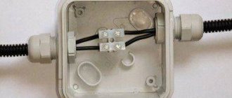
Zero break at the input or inside the distribution box.
If the neutral wire breaks in front of the distribution box or in the box itself, the problem with the neutral and the operation of electrical equipment will be precisely in the room of the house or apartment into which this box distributes voltage. At the same time, everything in the neighboring rooms will work as normal.
In the figure above you can see that in front of the left distribution box the neutral wire has broken, and the phase through the lamp filament (load) reaches the socket neutral.
When searching for such a fault, the problem box is opened and the common zero twist is found (it is the thickest in the box). The strands are cut off, re-cut and twisted together again.
Advice
. If the wire is copper, then it is advisable to solder the twist.
When the zero breaks in front of the distribution box, as shown in the top figure, to find the break, you often have to open the groove with this wire in the wall to find the location of the damage.
When searching for such a fault, first they find a twist in the box with a common zero and unwind it into separate wires. Then each neutral conductor is called up to the sockets and to the ceiling. The core that will not ring will be the incoming wire into the box.
Next, this wire is pulled through and the plaster in the wall is opened to look for where the wire is damaged. However, such a malfunction is classified as difficult to solve, because few people undertake to pick at the wall - it’s easier to lay a new route.
What to do if the measured short-circuit current is too low?
Let's say we measured it with a device and got the value of the short-circuit current in the socket (as a rule, the measurement is carried out at the most remote point). How can you tell if this current is too low? This is assessed by the criterion of guaranteed operation of the electromagnetic release of the circuit breaker in the measured circuit. It is logical that for this the short-circuit current must be greater than the upper limit of the tripping range. Let me remind you that for characteristic “B” the spread is 3…5 In, for “C” – 5…10 In, for “D” – 10…20 In. To be more precise, let’s turn to the PUE (clause 7.3.139):
7.3.139. In electrical installations up to 1 kV with a solidly grounded neutral, in order to ensure automatic shutdown of the emergency section, the conductivity of the neutral protective conductors must be selected such that, in the event of a short circuit to the housing or neutral protective conductor, a short-circuit current occurs that is at least 4 times greater than the rated current of the fuse link of the nearest fuse and at least 6 times the current of the circuit breaker release, which has an inverse current characteristic.
When protecting networks with automatic circuit breakers that have only an electromagnetic release (without a time delay), you should be guided by the requirements regarding the short-circuit current multiplicity and given in 1.7.79.
As I understand it, the first part of 7.3.139 only talks about the thermal release - its rated current must be at least 6 times less than the short-circuit current. The second part of this paragraph, as well as paragraph 1.7.79, talks about the maximum shutdown time during a short circuit (0.4 s), which must be provided only by an electromagnetic release. At the same time, it is not clearly indicated on the choice of AV taking into account its shutdown characteristics.
Because of this vagueness of the wording, they use the rule set out in PTEEP (checking the operation of protection in a power system with a grounded neutral, clause 28.4), which states that when a short circuit to the neutral protective conductor occurs, the short-circuit current must be at least “1.1 the upper value of the operating current of the instantaneous release.”
That is, for a B10 circuit breaker, the short-circuit current at the end of the line that it protects must be at least 10x5x1.1 = 55 A. If a C25 circuit breaker is installed, the short-circuit current must be at least 25x10x1.1 = 275 A.
If the short-circuit current is less, the permissible response time is by no means guaranteed. What to do? There are two ways out:
- increase the short-circuit current, this requires the cost of laying a new supply line (at least its weakest link),
- reduce the rating of the machine (for example, 25 A to 16) and the letter of the shutdown characteristic (from “C” to “B”) to the detriment of the maximum load power.
Read in more detail why it is always preferable to put “B” rather than “C” for group machines.
Zero break in the entrance panel of a house or apartment.
In the input panel of a house or apartment, the neutral wire may break at the input circuit breaker or at the neutral bus. As a rule, the screw connection becomes loose, causing contact between the wire and the clamp to be lost, or, in rare cases, the neutral wire breaks off at the clamp and hangs in the air.
Also, due to poor contact between the clamp and the wire, the wire heats up and burns and, as a result, a large transition resistance in the form of soot forms
, which gradually turns into a cliff.
If there is no zero, all electrical appliances in the house will not work. But if at least one household appliance remains plugged in or the light switch remains on, the phase through the radio components of the power supply
household appliances or
filament
will pass unhindered to the zero bus, and from the bus to all neutral wires of the electrical wiring. And as a result, there will be a phase on both sockets of sockets and contacts of switches. This is because all the neutral wires of the electrical wiring are connected together at the neutral bus.
To determine such a malfunction, it is enough to unplug all household appliances from the sockets and turn off all light switches or unscrew the light bulbs. After these actions, the second phase from the sockets and switch contacts will disappear. The malfunction is treated by restoring the contacts on the terminals of the input circuit breaker or on the zero bus.
Why do you need to know the values of the short-circuit current and the resistance of the “Phase-zero” loop?
I have already said a lot of things in the article. But what good is it to us to know these parameters of the power grid?
Knowing the short-circuit current (or the resistance of the “Phase-zero” loop) and the load power allows us to correctly and optimally (in terms of safety/functionality/reliability/price ) select the main elements of the power system - protection devices and cable cross-sections. A little more detail below.
Safety
I have already spoken about this, but I will repeat it. Electrical networks must be safe in all areas and in all modes. For this, in addition to insulation, circuit breakers and devices controlled by differential current (RCD) are used. Together with protective grounding, these devices protect equipment from short circuits and overloads, and people from the danger of direct or indirect contact.
Functionality
Knowing the short-circuit current, you can issue a conclusion about the need to install a stabilizer, or replace the cable line with a new one. In addition, we can draw a conclusion about selectivity - can it be ensured at least partially?
Reliability
In case of high short-circuit current, it is necessary to use switches with high breaking capacity for reliable operation at the moment of short-circuit. In addition, high demands must be placed on the quality of installation and components.
Price
It’s clear here - fulfilling the previous points significantly affects the price of the entire electrical network.
Additional information about finding the ground, phase, neutral wire
We remind you that we considered cases when there is no indicator screwdriver at hand, but there are current clamps and a multimeter. Then, before entering the apartment, they detect the ground, phase, neutral wire, and the home network is dialed. There are three cores, the technique is on the surface: between the phase and the other wire, the potential difference will be 230 volts. Please note that the technique is not suitable in other cases. For example, the voltage difference between two identical phase conductors is zero. It is difficult to measure and determine with a tester.
Let's add another method - it is prohibited by industry. A light bulb in a socket with two exposed wires. Using the tool, they find the phase; it is possible to short the core to ground. You cannot use water, gas, sewer pipes or other engineering structures. According to the rules, the cable antenna braid is equipped with grounding (grounding). In relation to it, it is permissible to use a tester (a light bulb in a socket prohibited by standards) to find the phase.
For determined people, we recommend fire escapes and steel tires for lightning rods. You need to clean the metal until it shines, call the phase phase. Please note that not all fire escapes are grounded (although they must be), lightning rod buses are 100%. If you discover such blatant arbitrariness, contact the management organizations; if there is no response, inform the government authorities. Indicate a violation of the rules for protective grounding of buildings.
Is high short-circuit current good or bad?
As I showed in the graph earlier, the further the fault location is from the power source, the lower the short circuit current will be because the line resistance will be greater. High short-circuit current usually occurs in those places of the power network that are located closest to the substation, and cable lines have a large cross-section of wires. In supply networks with a voltage of 0.4 kV, short-circuit currents of more than 6 kA are considered relatively high, and short-circuit currents above 15 kA are practically never encountered. So what we have:
Disadvantages of low short circuit current
- large voltage drop under sufficiently powerful load;
- As a rule, low voltage on electrical appliances. In this case, the stabilizer will not always help;
- instability of voltage on electrical appliances depending on the time of day or season. I conducted an investigation according to the voltage standards and its tolerances;
- high (up to infinity) response time of circuit breakers during a ground fault (only the thermal release works);
- the need to install circuit breakers with a shutdown characteristic of “B” in order to more likely trigger the electromagnetic release during a short circuit. This controversial issue is discussed in my article on Zen Why install machines with the “B” characteristic;
- mandatory installation of an RCD - in addition to its “main” responsibilities (switching off power at high leakage current, as well as to protect people during direct and indirect contact), the RCD performs the function of protection against ground faults (PUE 1.7.59, 7.1.72 ).
Pros of low short circuit current
- you can install cheap circuit breakers with a low rated maximum breaking capacity (Icn = 4500 A);
- It is relatively easy to ensure selectivity between the input and subordinate automata. But we need to calculate and measure the exact value of the short-circuit current,
- low starting current of electric motors and other inertial loads. Article What is inrush current, how to measure and calculate it.
Disadvantages of high short circuit current
- impossibility of ensuring selectivity between higher and lower-level machines. The solution is to install a switch or a time-selective circuit breaker;
- the need to install an AV with a high rated maximum breaking capacity (Icn = 6000, 10000 A, etc.). The breaking capacity must be higher than the short-circuit current at the beginning of the protected section (PUE clause 3.1.3);
- large negative consequences when a short circuit occurs.
Pros of high short circuit current
- it is easy to guarantee stable voltage at the load and the quality of electricity in general;
- there is a prospect of connecting new consumers and increasing the load;
- guaranteed line shutdown in case of short circuit.
Selectivity of circuit breakers and RCDs is a separate big topic, and there are plans.
Summarizing the pros and cons, we can say that the value of the short-circuit current is a double-edged sword. In the domestic sector, the short-circuit current is often low, and they try to increase it by laying new lines with a high cross-section of wires and installing new transformer substations. In serious energy, on the contrary, methods are used to reduce short-circuit current.
Combining phases from two inputs
From a purely technical standpoint, it is possible to implement such a scheme. In this case, contactors are used to disconnect 2 inputs. However, each input requires a separate meter, ASU, automatic devices, and its own grounding.
Usually no one does this, it's simply impractical. The following questions arise:
- Protection.
Circuit breakers connected in parallel will not act as protection as intended. Therefore, the electrical network will remain unprotected.
- Security.
If one of the 2 inputs is disconnected, for example, a local electrician or fireman switches off while extinguishing a fire, the voltage on the ASU (input distribution device) will still remain. The most dangerous thing here is that potential can come from the wrong direction. All this is fraught with negative consequences for humans.
- Approvals.
Inputting electrics into a house or apartment Source uk-parkovaya.ru
It is unlikely that anyone will approve a circuit with 2 inputs, the chances are zero.
Download
The same article, beautifully laid out and published in the paper magazine “Electrical Technical Market”:
• Short-circuit current: size matters / Article about short-circuit current, published in the magazine Elek.ru, pdf, 4.45 MB, downloaded: 626 times./
Respect and respect if you have read this far and intend to download books on this topic!
You are a serious person! • Shabad_M.A._Calculations_of_relay_protection_and_automation / Shabad M.A. Calculations of relay protection and automation. A good book from 1985, which tells about the design of electrical networks - from the equipment of substations to the selectivity of protective circuit breakers, pdf, 38.87 MB, downloaded: 1071 times./ • Belyaev A.V. Selection of equipment, protection and cables 0.4 kV / Belyaev A.V. Selection of equipment, protection and cables 0.4 kV - a book for the theoretical calculation of short circuit current. St. Petersburg 2008, pdf, 17.39 MB, downloaded: 839 times./ • RD 153-34.0-20.527-98 / Guidelines for calculating short circuit currents and choosing electrical equipment RD 153-34.0-20.527-98. The guidelines are intended for use by energy engineers when performing calculations of short circuit currents (SC) and testing electrical equipment (conductors and electrical apparatus) under the SC mode. MPEI, 1998, pdf, 3.61 MB, downloaded: 790 times./ • Electrical part of power plants and transformer substations / Electrical part of power plants and substations. Detailed description of circuits and calculations with examples. Tutorial. N.V. Kolomiets, Tomsk Polytechnic, 2007, pdf, 1.37 MB, downloaded: 735 times./ • Selection of electrical equipment and calculations of transformer substations / Selection of electrical equipment and calculations of medium and low voltage transformer substations. ABB, educational manual, pdf, 9.16 MB, downloaded: 681 times./ • Kharechko V.N., Kharechko Yu.V. Automatic switches of modular design / Kharechko V.N., Kharechko Yu.V.
Automatic circuit breakers of modular design: Reference manual. The reference manual sets out the requirements of GOST R 50345-99 (IEC 60898-95) for household circuit breakers intended for overcurrent protection, examines the design of circuit breakers, gives characteristics and their classification. Errors are analyzed that are partially corrected in the new version of GOST R 50345-2010, pdf, 7.17 MB, downloaded: 1102 times./ I look forward to questions and comments in the comments!