Operating modes of electrical circuits
An electrical circuit, depending on the value of the load resistance R, can operate in various characteristic modes:
· nominal
· agreed upon;
· idle move;
· short circuit.
The nominal mode is the design mode in which the circuit elements (sources, receivers, power lines) operate under conditions corresponding to the design data and parameters.
The insulation of the source, power line, and receivers is designed for a certain voltage, called the rated voltage. Exceeding this voltage leads to insulation breakdown, increased current in the circuit and other emergency consequences.
The thermal regime of energy sources or receivers is designed to release a certain amount of heat in them, that is, for a certain power, and the latter depends on the square of the current RI2, rI2.
The thermal current calculated is called the rated current.
The rated power value for an electrical energy source is the maximum power that the source, under normal operating conditions, can deliver to an external circuit without the danger of insulation breakdown and exceeding the permissible heating temperature.
For electrical energy receivers such as motors, this is the power that can be developed at the shaft under normal operating conditions. For other receivers of electrical energy (heating and lighting devices) this is their power at nominal mode. Rated values of voltages, currents and powers are indicated in product data sheets.
Matched mode of operation is the mode in which the electrical circuit (source and receiver) operates when the load resistance R is equal to the internal resistance of the source r. This mode is characterized by the transfer of the maximum possible power from a given source to the receiver. However, in a coordinated mode, the E.P.D. h = 0.5 is low and for high-power circuits operation in a coordinated mode is not economically profitable. Matched mode is used mainly in low-power circuits if the efficiency. is not significant, but it is necessary to obtain as much power as possible in the receiver.
No-load and short circuit mode. These modes are the limiting modes of operation of the electrical circuit.
In idle mode, the external circuit is open and the current is zero. Since the current is zero, the voltage drop across the internal resistance of the source is also zero (rI = 0) and the voltage at the source terminals is equal to the emf (e = U). From these relationships follows the method of measuring the EMF (2.7) of the source: with the external circuit open, a voltmeter whose resistance can be considered infinitely large is used to measure the voltage at its terminals.
In short circuit mode, the source terminals are connected to each other, for example, the load resistance is closed by a conductor with zero resistance. The voltage at the receiver is zero.
The resistance of the entire circuit is equal to the internal resistance of the source, and the short circuit current in the circuit is equal to:
Ik.z. = e/r.
(2.14)
It reaches the maximum possible value for a given source and can cause overheating of the source and even damage it. To protect sources of electrical energy and supply circuits from short circuit currents, fuses are installed in low-power circuits, circuit breakers are installed in more powerful circuits, and special high-voltage circuit breakers are installed in high-voltage circuits.
It is known that an electrical circuit is a collection of certain devices that provide a constant, continuous passage of electric current. The circuit cannot operate if any elements are missing; Both sources of energy and its conductors must be present, and receivers, as a rule, are the main devices that form this circuit. If we consider that in an electrical circuit there are various elements that are divided into three main groups: energy sources, current conductors and receivers, i.e., those elements that are powered by current and convert energy into its other types, then we can assume that there are different modes of operation of electrical circuits. Basic operating modes of electrical circuits As mentioned earlier, any electrical circuit can have a rather complex structure, depending on the number of elements in it and its branching. All this leads to the fact that the circuit can operate in different modes. There are three main operating modes: load (or matched), short circuit mode, and idle mode. They differ from each other in the load on the electrical circuit. You can also select the nominal operating mode. In this mode of operation, all devices in the circuit operate under the conditions specified for them as optimal. These characteristics are prescribed by the manufacturer in the passport data when the device is manufactured at the factory. Load, or coordinated operating mode . If any receiver is connected to an energy source in an electrical circuit, then it has a certain resistance. Such a receiver can be any device, for example a light bulb. If there is voltage, then Ohm's law , thus, the emf of the source is obtained from the sum of the voltages of the external section of the circuit and the internal resistance of the source. The voltage drop in the external circuit will be equal to the voltage at the source terminals. It depends on the load current: the lower the load resistance, the higher the current and, accordingly, the lower the voltage at the terminals of the circuit’s power source. In other words, we can say that the load or coordinated operating mode is a mode in which a high-power load is transferred from a source. In this mode, the load resistance is equal to the internal resistance of the source, and maximum power is consumed. However, this mode is not recommended, since if the nominal values are exceeded for a long time, the devices may fail. Idle mode . This mode of operation of the electrical circuit characterizes its open state - there is no current, and all elements are disconnected from the power source. In this state of the circuit, the internal voltage drop is zero, and the voltage at the terminals of the power source coincides with the emf of the source. That is, we can say that the idle mode characterizes the electrical circuit when it is in an open state and the load resistance is completely absent or disconnected. This state of the circuit can be used to measure the EMF of the power source. Short circuit mode . This operating mode is considered an emergency; the electrical circuit cannot operate normally. A short circuit occurs when two different points in a circuit are connected, the potential difference of which is different. This condition is not intended by the device manufacturer and interferes with its normal operation. In this operating mode, the terminals of the energy source are closed by a conductor (“shorted”), and its resistance is close to zero. Often, a short circuit occurs in cases where two wires are connected that connect the source and receiver in the circuit; as a rule, their resistance is negligible, so it can be called zero. When a short circuit occurs, the current in the circuit significantly exceeds the rated values (due to the lack of resistance). This can render the power source and receivers in the electrical circuit unusable. In some cases, this is the result of improper actions on the part of personnel working with electrical equipment.
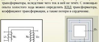
The principle of operation of the transformer in idle mode
When a sinusoidal voltage is applied to the winding of the device, a weak current appears in it, usually not exceeding 0.05-0.1 of the rated value (this is the no-load current).
It is created by a winding magnetomotive force; it is because of its action that a leading magnetic flux (denoted F) and a scattering flux F1, closed around the winding body, arise in a closed magnetic conductor element. The value of the magnetomotive force is equal to the product of the no-load current and the number of winding turns. How to calculate electrical energy consumption
The leading flow creates two electromotive forces in the device: self-induction in the first winding and mutual induction in the second. F1 produces a leakage emf at the first coil. It has a very small value, because the flow that creates it is closed, for the most part, through air masses, the leading flow F is through the magnetic circuit. Since the main flow has a much larger scale, the electromotive force it generates for the primary coil is also much larger.
Important! Since the supplied voltage has the form of a sinusoid, the main flow and the winding electromotive forces created by it have the same characteristics. But due to magnetic saturation, the flux present in the device is disproportionate to the electric current that creates magnetization, so the latter will not be sinusoidal. It is practiced to replace its real curve with a corresponding sinusoid with the same value. Current distortion is associated with the third harmonic component (a value determined by eddy flows and magnetic saturation).