Work to move a charge in a uniform electrostatic field
If an electrostatic field acts with some force on electrically charged bodies, then it is capable of doing work to move these bodies.
Let in a uniform electrostatic field of intensity
Let us calculate the work A performed by the force acting on the charge from the electrostatic field. By definition of work: A=Fscosα .
The field is homogeneous, therefore the force is constant, its modulus is equal to: F=qE, and scosα=d=is the projection of the displacement vector onto the direction of the field lines. Consequently, the work done by the forces of a uniform electrostatic field to move an electric charge q from point 1 to point 2 ( ) is equal to:
Note! If in this case the charge did not move from point 1 to point 2, but vice versa, then the sign of the work would change to the opposite, that is, the work would be done against the field forces.
Note! The formula will be valid in cases of charge movement along any trajectory. That is, a uniform electrostatic field is potential .
Any electrostatic field is potential: the work of electrostatic (Coulomb) forces (as well as the work of gravitational forces) does not depend on the shape of the trajectory along which the charge moves, but is determined by the initial and final positions of the charge. If the trajectory of the charge is closed, the work done by the field forces is zero.
Potential energy of a charged body in a field created by a point charge
A charged body placed in an electrostatic field, like a body located in the Earth’s gravitational field, has potential energy. The potential energy of a charge in an electric field is usually denoted by the symbol. According to the potential energy theorem, the change in the potential energy of a charge, taken with the opposite sign, is equal to the work done by the electrostatic field to move the charge from point 1 to point 2 of the field:
The potential energy of interaction between two point charges Q and q, located at a distance r from each other, is determined by the formula:
Please note: 1) the potential energy of interaction of charges is positive (> 0), if the charges are of the same name, and negative ( = 0 (charges will not interact). Thus, the potential energy of interaction of two point charges is equal to the work that the electrostatic field must do to increase the distances between these charges from r to infinity.
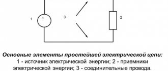
Potential distribution in an electrical circuit. Potential diagram
When calculating electrical circuits, uncertainty often arises in determining the potential difference between individual points of the circuit and the distribution of the circuit potential.
To solve this problem, you first need to calculate the currents in the branches of the circuit.
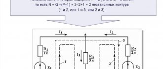
Next, the potential of one of the points in the chain (any), for example, the point in Fig. 1.19, is taken equal to zero (sometimes this point is shown grounded on the diagram, Fig. 1.19a) and the potentials of all characteristic points selected for constructing the potential circuit diagram a,1,b,c,d,2,a are calculated.
Fig.1.19
(1.1.47)
Having determined Rz= R1+ R1+ R4+ R3 and choosing the scales Mφ=Mr, a potential diagram is constructed (Fig. 1.19b).
Thus, a potential diagram is understood as a graph of the distribution of potential φ along the elements of a closed circuit of an electrical circuit depending on the value of the total from the “base” point “a” to each subsequent point of this circuit in the selected (indicated) direction of bypassing the circuit.
If the traversal is carried out along branches consisting of several series-connected elements, then a dividing point is indicated between each pair of these elements and its potential is plotted on the diagram.
The vertical sections of the diagram are connected by points on the diagram, between which ideal sources of emf are located in the diagram.
The potential φa=φ2-E3 should be equal to zero (increases to the starting point of the contour), i.e. the last expression in (1.47) is a test one.
A potential diagram allows you to determine the voltage between any points in the circuit (the potentials of which are plotted on the diagram). In addition, it is possible to determine in the circuit the presence of points of the same potential, which, if necessary, can be connected to each other without disturbing the distribution of currents in the equivalent circuit of the electrical circuit. Knowing the location of points with the maximum potential allows you to set requirements for the quality of insulation.
When calculating electrical circuits, uncertainty often arises in determining the potential difference between individual points of the circuit and the distribution of the circuit potential.
To solve this problem, you first need to calculate the currents in the branches of the circuit.
Next, the potential of one of the points in the chain (any), for example, the point in Fig. 1.19, is taken equal to zero (sometimes this point is shown grounded on the diagram, Fig. 1.19a) and the potentials of all characteristic points selected for constructing the potential circuit diagram a,1,b,c,d,2,a are calculated.
Fig.1.19
(1.1.47)
Having determined Rz= R1+ R1+ R4+ R3 and choosing the scales Mφ=Mr, a potential diagram is constructed (Fig. 1.19b).
Thus, a potential diagram is understood as a graph of the distribution of potential φ along the elements of a closed circuit of an electrical circuit depending on the value of the total from the “base” point “a” to each subsequent point of this circuit in the selected (indicated) direction of bypassing the circuit.
If the traversal is carried out along branches consisting of several series-connected elements, then a dividing point is indicated between each pair of these elements and its potential is plotted on the diagram.
The vertical sections of the diagram are connected by points on the diagram, between which ideal sources of emf are located in the diagram.
The potential φa=φ2-E3 should be equal to zero (increases to the starting point of the contour), i.e. the last expression in (1.47) is a test one.
A potential diagram allows you to determine the voltage between any points in the circuit (the potentials of which are plotted on the diagram). In addition, it is possible to determine in the circuit the presence of points of the same potential, which, if necessary, can be connected to each other without disturbing the distribution of currents in the equivalent circuit of the electrical circuit. Knowing the location of points with the maximum potential allows you to set requirements for the quality of insulation.
Properties of potential
Among the important properties of potential, the following should be noted:
- if the field is created by several charges, then the potential at a specific point will be equal to the algebraic (taking into account the sign of the charge) sum of the potentials created by each of the charges φ=φ1+φ2+φ3+φ4+φ5+…+φn;
- if the distances from the charges are such that the charges themselves can be considered point-like, then the total potential is calculated using the formula φ=k*(q1/r1+q2/r2+q3/r3+…+qn/rn), where r is the distance from the corresponding charge then the point in question.
If the field is formed by an electric dipole (two connected charges of opposite signs), then the potential at any point located at a distance r from the dipole will be equal to φ=k*p*cosά/r2, where:
- p is the electric arm of the dipole, equal to q*l, where l is the distance between charges;
- r – distance to the dipole;
- ά is the angle between the dipole arm and the radius vector r.
If the point lies on the dipole axis, then cosά=1 and φ=k*p/r2.