In practice, there are often problems of calculating the parameters of currents and voltages in various branched circuits. Kirchhoff's rules are used as a tool for calculations (in some literature they are also called laws, although this is not entirely correct) - one of the fundamental rules that, together with Ohm's laws, allows one to determine the parameters of independent circuits in the most complex circuits.
The scientist Gustav Kirghoff formulated two rules [], for the understanding of which the concept of a node, branch, and contour was introduced. In our situation, we will call a branch a section through which the same current flows. The connecting points of the branches form nodes. The branches, together with the nodes, form contours - closed paths along which current flows.
Kirchhoff's first rule
Gustav Kirchhoff's first rule is formulated based on the law of conservation of charge. The physicist understood that the charge cannot be retained in the node, but is distributed along the branches of the circuit that form this connection.
Kirchhoff assumed, and subsequently substantiated on the basis of experiments, that the number of charges entering the node is the same as the amount of current flowing out of it.
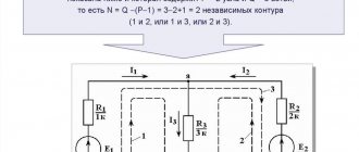
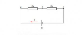
Figure 1 shows a simple circuit diagram. Points A, B, C, D indicate the contour nodes in the center of the diagram.
Rice. 1. Circuit diagram
Current I1 enters node A, formed by the branches of the circuit. In the diagram, the electric charge is distributed in two directions - along branches AB and AD. According to Kirchhoff's rule, the incoming current is equal to the sum of the outgoing ones: I1 = I2 + I3.
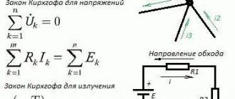
Figure 2 shows an abstract node, along the branches of which current flows in different directions. If you add the vectors i1, i2, i3, i4, then, according to Kirchhoff’s first rule, the vector sum will be equal to 0: i1 + i2 + i3 + i4 = 0. There can be as many branches as you like, but the equality will always be fair, taking into account the direction of the vectors .
Rice. 2. Abstract node
Let us write our conclusions in algebraic form for the general case:
To use this formula, you need to take into account the signs. To do this, you need to select the direction of one of the current vectors (no matter which one) and designate it with a plus sign. In this case, the signs of all other quantities are determined based on their direction in relation to the selected vector.
To avoid confusion, the current directed to the node point is considered positive, and the vectors directed from the node are considered negative.
Let us state Kirchhoff’s first rule, expressed by the above formula: “The algebraic sum of the currents converging in a certain node is equal to zero, if we consider the incoming currents to be positive and the outgoing currents to be negative.”
The first rule complements the second rule formulated by Kirchhoff. Let's move on to consider it.
Branched chains. Kirchhoff's rules.
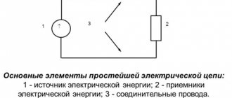
Kirchhoff's laws
for a branched circuit (a branched circuit is an electrical circuit containing nodes - places where at least three conductors meet):
a) According to Kirchhoff’s first law
–
the algebraic sum of currents converging at a node is equal to zero
. Currents arriving at a node are considered positive, and currents leaving the node are considered negative.
b) Kirchhoff's second law
:
in a closed circuit, the algebraic sum of the products of currents in sections and the resistance of these sections is equal to the algebraic sum of the electromotive forces included in a given circuit
,
where is the algebraic sum of current strengths converging at a node; – algebraic sum of the products of current strengths and resistances of closed sections; – algebraic sum of the emf of current sources in a closed section of the circuit.
When calculating complex DC circuits using Kirchhoff's rules, it is necessary:
1. Select an arbitrary direction of currents in all sections of the circuit.
2. Select the direction of bypassing the contour; the product is positive if the current in the section coincides with the direction of the bypass, and vice versa; EMF acting in the selected bypass direction (movement occurs inside the current source from the cathode to the anode) are considered positive.
3. Compose so many equations so that their number is equal to the number of unknown electrical quantities; each circuit under consideration must contain at least one element not contained in previous circuits.
Kirchhoff's first rule:
the algebraic sum of the currents converging at a node is equal to zero:
For example, for fig. 148 Kirchhoff’s first rule will be written as follows:
Kirchhoff's first rule follows from the law of conservation of electric charge. Indeed, in the case of a steady direct current, electric charges should not accumulate at any point of the conductor or in any section of it. Otherwise the currents could not remain constant.
Kirchhoff's second rule is derived from Ohm's generalized law for branched chains. Let's consider a contour consisting of three sections (Fig. 149). We will take the clockwise direction of traversal as positive, noting that the choice of this direction is completely arbitrary. All currents that coincide in direction with the direction of bypassing the circuit are considered positive, and those that do not coincide with the direction of bypassing are considered negative. Current sources are considered positive if they create a current directed towards bypassing the circuit. Applying Ohm's law (100.3) to sections, we can write:
Adding these equations term by term, we get
(101.1)
Equation (101.1) expresses Kirchhoff's second rule
: in any closed circuit, arbitrarily chosen in a branched electrical circuit, the algebraic sum of the products of the current strengths
Ii
and the resistance
Ri
of the corresponding sections of this circuit is equal to the algebraic sum of the emf.
, occurring in this circuit: (101.2)
When calculating complex DC circuits using Kirchhoff’s rules, it is necessary:
1. Select arbitrary
direction of currents in all sections of the circuit; the actual direction of the currents is determined when solving the problem: if the desired current turns out to be positive, then its direction was chosen correctly, if negative, its true direction is opposite to the chosen one.
2. Choose the direction of traversing the contour and strictly adhere to it; product IR
positive if the current in a given section coincides with the direction of the bypass, and, conversely, the emf acting in the selected direction of bypass is considered positive, and against it - negative.
3. Compose so many equations so that their number is equal to the number of desired quantities (the system of equations must include all the resistance and emf of the circuit in question); each contour under consideration must contain at least one element not contained in the previous contours, otherwise the resulting equations are a simple combination of those already composed.
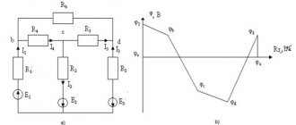
As an example of using Kirchhoff's rules, consider the diagram (Fig. 150) of a Wheatstone measuring bridge
* Resistances
R
1
, R
2
, R
3 and
R
4 form its “shoulders”.
A battery with emf is connected
between points A
and
B and resistance r
,
a galvanometer with resistance
RG
C
and
D. For nodes
A, B
and
C,
applying Kirchhoff’s first rule, we obtain
(10 1.3)
For ACVA, ACDA
and
CBDC,
according to Kirchhoff’s second rule, can be written:
(101.4)
* C. Wheatstone (1802-1875) - English physicist.
If all resistances and emfs are known, then by solving the six equations obtained, the unknown currents can be found. By changing known resistances R
2,
R
3 and
R
4
,
it is possible to ensure that the current through the galvanometer is zero (
IG
= 0)
.
Then from (101.3) we find
(101.5)
and from (101.4) we get
(101.6)
From (101.5) and (101.6) it follows that
(101.7)
Thus, in the case of an equilibrium bridge ( IG
= 0) when determining the required resistance
R
1 emf. batteries, battery resistance and galvanometer do not play a role.
In practice, a Wheatstone rheochord bridge
(Fig. 151), where the resistances R
3 and
4
represent a long homogeneous wire (rheochord) with a high resistivity, so that the ratio R
3
/
4
can be replaced by the ratio l
3
l
4.
Then, using expression (101.7), can be written down
(101.
Lengths l
3 and
l
4 are easily measured on a scale, and
R
2 is always known.
Therefore, equation (101.8) allows us to determine the unknown resistance R
1.
BRANCHED CHAINS
Parallel connection of receivers. First, let's look at the graphic-analytical method for calculating a circuit with a parallel connection of consumers (Fig. 2.16, a
). Such a circuit is characterized by the fact that the voltages on each branch are the same, the total current is equal to the sum of the branch currents.
The current in each branch is determined by Ohm's law:
| I 1 = | U | ; I 2 = | U | ; I 3 = | U | ( xL 3 > xC 3). |
| √ r 12 + xL 12 | √ r 22 + xC 22 | √ r 32 + ( xL 3 - xC 3)2 |
The shift angle φ between the current of each branch and the voltage is determined using cos φ:
| cos φ1 = | r 1 | ; cos φ2 = | r 2 | ; cos φ3 = | r 3 | . |
| √ r 12 + xL 12 | √ r 22 + xC 22 | √ r 32 + ( xL 3 - xC 3)2 |
|
The total current in the circuit, as follows from Kirchhoff’s first law, is equal to the geometric sum of the currents of all branches:
Ī
=
Ī
1 +
Ī
2 +
Ī
3.
The value of the total current is determined graphically using the vector diagram in Fig. 2.16, b
.
The active power of the circuit is equal to the arithmetic sum of the active powers of all branches:
P = P
1
+ P
2
+ P
3
.
The reactive power of the circuit is equal to the algebraic sum of the reactive powers of all branches:
| n | ||
| Q = | ∑ | Qk. |
Moreover, the reactive power of the branches with inductance is taken with a plus sign, and the branches with capacitance - with a minus sign. For the circuit fig. 2.16 reactive power is equal to
Q
=
QL
1 -
QC
2 +
QL
3 -
QC
3.
Full circuit power
S = √ P
2 +
Q
2.
The shift angle φ between the total current and voltage is determined from the vector diagram or from the expression:
cos φ = P/S.
The graphic-analytical method is not convenient for calculating branched circuits: it is cumbersome and has a low degree of accuracy.
To analyze and calculate branched AC circuits, conductivities are used, with the help of which a branched circuit can be converted into a simple circuit and the currents and voltages of all its sections can be analytically calculated.
In DC circuits, conductivity is the reciprocal of the resistance of a section of the circuit:
g
= 1/
r
and the current in the circuit is expressed as the product of voltage and conductivity:
I = Ug.
| Rice. 2.17. Electric circuit ( a ), its vector diagram ( b ) and equivalent circuit ( c ); vector diagram of a circuit at resonance |
In alternating current circuits there are three conductivities - full,
active and reactive, and only the admittance is the reciprocal of the total resistance of the series section of the circuit.
Expressions for conductivities in alternating current circuits can be obtained as follows.
The current in each unbranched section of the circuit is decomposed into two components, one of which is a projection onto the voltage vector (the active component of the current I
a), and the other - to a line perpendicular to the voltage vector (reactive component of the current
I
r).
The active component of the current determines the active power
P
=
UI
cos φ =
UI
a ;
reactive component of current - reactive power
Q = UI
sin φ =
UI
r.
From the vector circuit diagram fig. 2.17, a
, shown in Fig.
2.17, b
, it follows that the active component of the current
I
1 is equal to
| I 1a = I 1 cos φ1 = | U | r | = Ur 1 /z 12 = Ug 1 . |
| z 1 | z 1 |
Magnitude
g
1 =
r
1
/z
12
called active conductance of the branch. Reactive component of current I
1 is equal
| I lp = I 1 sin φ1 = | U | xL | = UxL/z 12 = Ub 1. |
| z 1 | z 1 |
Magnitude
b
1 =
xL/z
12 =
bL
1
is called the reactive conductance of a branch of a circuit with inductance and is generally denoted bL.
Active g
2 and reactive
b
2 conductivity of the second branch of the circuit:
I
2a =
I
2cos φ2 =
U/z
2 •
r
2
/z
2
= Ug
2 ;
g
2
=r
2
/z
22;
I
2p =
I
2 sin φ2 =
U/z
2 •
xC /z
2
= Ub
2;
b
2
= bC
2
= xC
2
/z
22
.
The reactive conductivity of the branch with capacitance is generally denoted bC.
The current vector of the first branch is equal to the geometric sum of the vectors of the active and reactive current components
Ī
1 =
Ī
1a +
Ī
1р,
and the current value
I
1 = √
I
1а2 +
I
1р2.
Expressing the current components in terms of voltage and conductivity, we obtain
I
1 = √(
Ug
1)2 + (
UbL
1)2
= U
√
g
12 +
bL
12 =
Uу
1
= U/z
1
,
where y
1 = 1
/z
1
=
√
g
12 +
bL
12 - total conductance of the branch.
The total conductivity of the second branch is determined similarly:
at
2
=
1
/z
2
=
√
g
22 +
bС
2.
Equivalent active, reactive and admittance circuits are obtained as follows.
The vector of the total current of the circuit is equal to the geometric sum of the current vectors Ī
1 and
Ī
2:
Ī
=
Ī
1
+ Ī
2
and can be expressed through the active and reactive components of the current and the equivalent conductance of the entire circuit:
Ī
=
Ī
a +
Ī
r
= Ūg
e +
Ūb
e =
Uу
e
= U/z
e
.
Active component of the total current (see Fig. 2.17, b
) is equal to the arithmetic sum of the active components of the branch currents:
(2.24)
I
a =
I
1a +
I
2a =
Ug
1 +
Ug
2 =
U
(
g
1 +
g
2) =
Ug
e
.
and the reactive component is the arithmetic difference of the reactive components of these currents:
(2.25)
I
р =
I
1р +
I
2р =
UbL
1
- UbC
2 =
U
(
bL
1
- bC
2) =
Ub
e.
| Rice. 2.18. To the calculation of a branched chain using conductivities |
From expressions (2.24) and (2.25) it follows that the equivalent active conductivity of the circuit is equal to the arithmetic sum of the active conductances of parallel-connected branches:
(2.26)
g
e =
g
1 +
g
2 + …
+ gn
,
and the equivalent reactive conductance is the algebraic sum of the reactive conductivities of parallel-connected branches:
(2.27)
b
e =
bL
1 +
bС
2
+ …
+
bLn + bSp.
In this case, the conductivities of branches with an inductive nature of the load are taken with a plus sign, and those of branches with a capacitive nature of the load - with a minus sign. Total equivalent conductivity of the circuit
(2.28)
at
e
=
1/ze = √
g
e2 +
b
e2
.
Based on the equivalent active, reactive and admittance, it is possible to determine the parameters of the equivalent circuit (Fig. 2.17, c) of the circuit.
The equivalent active, reactive and impedance circuits are determined using the expressions
z
e = 1/
y
e,
r
e =
g
e
z
e2
, x
e =
b
e
z
e2.
It should be noted that if Σ bL
> Σ
bC
, then the equivalent resistance
x
e will be inductive, if Σ
bC
> Σ
bL -
capacitive.
Mixed connection of consumers.
Calculation of a circuit with a mixed connection of consumers (Fig. 2.18,
a
) can be made by replacing it with the simplest equivalent circuit.
To do this, first determine the active, reactive and admittances of parallel-connected branches: g
1,
g
2,
b
1,
b
2,
y
1,
y
2.
Then the equivalent active, reactive and total conductivities of the parallel section of the circuit are found:
g
e
= g
1+
g
2;
b
e
= b
1
+ b
2;
y
e
=
√
g
e2 +
b
e2.
Next, determine the equivalent active, reactive and impedance of the parallel section of the circuit:
r
e =
g
e
z
e2;
x
e =
b
e
z
e2;
z
e = 1/
y
e.
As a result of calculations, the circuit can be replaced by an equivalent circuit (Fig. 2.18, b
), where all resistances are connected in series. The total active, reactive and impedance of the circuit are equal
r
ob =
r
e +
r.
x rev =
x ± x
e,
z
rev = √
r
rev2 +
x
rev2.
The chain takes on the simplest form shown in Fig. 2.18, c. The total current of the circuit is determined by Ohm's law:
I = U
/
z
about
Voltage between points a and b
Uab = Iz
e
= I/y
e
.
The currents in parallel branches are equal
I
1
= Uab at
1,
I
2
= Uab at
2.
Kirghoff's second rule
From Maxwell's third equation, Kirchhoff's rule for stresses follows. It is also called the second law.
This rule states that in a closed loop, on resistive elements, the algebraic sum of voltages (including internal ones) is equal to the sum of the emfs present in the same closed loop.
In this case, currents and EMF, the vectors of which coincide with the direction (selected arbitrarily) of bypassing the circuit, are considered positive, and currents counter to the bypass are considered negative.
Rice. 4. Illustration of Kirchhoff's second rule
The formulas shown in the figure are used in special cases to calculate the parameters of simple circuits.
Formulations of general equations:
, where where Lk and Ck are inductances and capacitances, respectively.
Linear equations are valid for both linear and nonlinear linearized circuits. They are used for any nature of temporary changes in currents and voltages, for different sources of EMF. Moreover, Kirchhoff's laws are also valid for magnetic circuits. This allows you to perform calculations to find the appropriate parameters.
What is Kirchhoff's stress rule (Kirchhoff's second law)?
The principle known as Kirchhoff's stress rule (discovered in 1847 by the German physicist Gustav R. Kirchhoff) can be stated as follows:
“The algebraic sum of all voltages in a closed loop is zero”
By algebraic I mean, in addition to taking into account quantities, taking into account signs (polarities). By contour I mean any path traced from one point in a chain to other points in that chain, and finally back to the starting point.
Kirchhoff's law for a magnetic circuit
The use of independent equations is also possible when calculating magnetic circuits. The Kirchhoff rules formulated above are also valid for calculating the parameters of magnetic fluxes and magnetizing forces.
Rice. 4. Magnetic circuits
In particular: ∑Ф=0.
That is, for magnetic fluxes, Kirchhoff’s first rule can be expressed in the words: “The algebraic sum of all possible magnetic fluxes relative to a node of a magnetic circuit is equal to zero.
Let us formulate the second rule for magnetizing forces F: “In a closed magnetic circuit, the algebraic sum of magnetizing forces is equal to the sum of magnetic stresses.” This statement is expressed by the formula: ∑F=∑U or ∑Iω = ∑НL, where ω is the number of turns, H is the magnetic field strength, and the symbol L denotes the length of the center line of the magnetic circuit. (It is conventionally assumed that each point of this line coincides with the lines of magnetic induction).
The second rule used to calculate magnetic circuits is nothing more than an alternative form of representing the total current law.
Note: When composing equations using formulas arising from Kirchhoff's rules, one must first determine the positive direction of the flows operating in the branches, comparing them with the direction of the bypasses of existing circuits.
When the magnetic flux vectors coincide with the bypass directions (in some sections), we take the voltage drop on these branches with the “+” sign, and those counter to it with the “–” sign.
Calculation methods using Kirchhoff's first and second laws
Let's start putting the theoretical material into practice. To correctly place the signs in the equations, you need to choose the direction of traversing the contour. Look at the diagram:
We suggest choosing a clockwise direction and indicating it in the figure:
The dash-dotted line indicates how to follow the contour when composing equations.
The next step is to create equations using Kirchhoff's laws. Let's use the second one first. We place the signs like this: a minus is placed in front of the electromotive force if it is directed counterclockwise (the direction we selected in the previous step), then for an EMF directed clockwise, we put a minus. We compose for each contour taking into account the signs.
For the first, we look at the direction of the EMF, it coincides with the dash-dotted line, put E1 plus E2:
For the second:
For the third:
The signs of IR (voltage) depend on the direction of the loop currents. Here the rule of signs is the same as in the previous case.
IR is written with a positive sign if the current flows in the direction of bypassing the circuit. And with a “–” sign if the current flows against the direction of bypassing the circuit.
The direction of traversal of the contour is a conditional value. It is needed only for arranging signs in equations, it is chosen arbitrarily and does not affect the correctness of the calculations. In some cases, an unsuccessfully chosen traversal direction may complicate the calculation, but this is not critical.
Let's look at another circuit:
There are as many as four sources of EMF, but the calculation procedure is the same, first we select the direction for composing the equations.
Now you need to create equations according to Kirchhoff's first law. For the first node (number 1 on the left in the diagram):
I3 flows in, and I1, I4 flows out, hence the signs. For the second:
For the third:
Question: “There are four nodes, but only three equations, why?” The fact is that the number of equations of Kirchhoff’s first rule is equal to:
Nequations=nnodes-1
Those. there are only 1 fewer equations than nodes, because This is enough to describe the currents in all branches; I advise you to go back to the diagram again and check whether all the currents are written down in the equations.
Now let's move on to constructing equations using the second rule. For the first circuit:
For the second circuit:
For the third circuit:
If we substitute the values of real voltages and resistances, then it turns out that the first and second laws are valid and are satisfied. These are simple examples; in practice, much more complex problems have to be solved.
Conclusion . The main thing when calculating using Kirchhoff’s first and second laws is to follow the rules for composing equations, i.e. take into account the directions of current flow and circuit bypass for the correct placement of signs for each element of the circuit.
Result
Great!
Try again(
Selecting the direction of currents
is unknown when calculating the circuit , then when drawing up equations according to Kirchhoff’s law, they must first be selected arbitrarily and indicated on the diagram with arrows. In reality, the direction of currents in the branches may differ from those arbitrarily chosen. Therefore, the selected current directions are called positive directions. If, as a result of the circuit calculation, any currents are expressed as negative numbers, then the actual directions of these currents are opposite to the selected positive directions.
For example
Figure 2
Figure 2a shows the electrical unit. Arbitrarily, we indicate the directions of the currents with arrows (Figure 2, b).
Important! When choosing the direction of currents in branches, two conditions must be met: 1. The current must flow from the node through one or more other branches; 2. At least one current must enter the node.
Let us assume that after calculating the circuit the following current values are obtained:
I1 = -5 A; I2 = -2 A; I3 = 3 A.
Since the current values I1 and I2 turned out to be negative, therefore, the directions of I1 and I2 are indeed opposite to those previously selected (Figure 3).
Figure 3 - the actual direction of the currents is indicated by blue arrows
- I1 − I2 + I3 = 0;
- -5 − (-2) +3 = 0;
- -I1 + I2 + I3 = 0;
- -5 + 2 +3 = 0.