To correctly select and check conductors (cables and busbars), as well as transformers for economic current density and, accordingly, throughput, calculate losses and voltage deviations, select compensation and protection devices, it is necessary to know the electrical loads of the facility being designed.
The basis for a rational solution to the issues of power supply of modern enterprises and energy systems is the correct determination of electrical loads. When loads are overestimated, unnecessary costs appear, as well as underutilization of the capacity of expensive equipment. If underestimated, it can lead to overloads of the energy system and undersupply of products. Neither the first nor the second option is acceptable. This task is further complicated by the fact that there are quite a lot of factors and dependencies that are difficult to take into account during design.
Total power and its components
Electrical power (P) in physics is a measure that shows how quickly the transformation or transfer of electricity occurs. The unit of measurement is watt (W, W). The value of P depends on the voltage (U) and current (I) in the closed circuit.
For direct current, the load consumed by P is the result of the product of current and voltage:
P = I*U (A*B = W).
P in a constant current circuit
Attention! In this case, the values of both electrical characteristics are constant, which means that at every second of time their values are instantaneous.
The formula changes form if there is a source of electromotive force E (EMF) in the circuit:
P = I*E.
For circuits where the current changes its values periodically along a sinusoid, this formula is not suitable. It is necessary to calculate P based on its instantaneous values in the time interval.
The total power S in its value corresponds to the expression:
S = U*I,
Where:
- U – potential difference at the terminals, (V);
- I – current, (A).
To designate S, use the non-systemic unit B*A (V*A).
Loads included in variable current circuits can be:
- active;
- reactive: capacitive or inductive.
Active load (AH)
A similar load is the elements of devices that have active resistance. The working part of such devices heats up when electricity passes through them.
The current passing through the load does work, which is spent on heating and releasing thermal energy. How is this load measured? It is measured in ohms (ohms).
Examples of AN include: iron, electric stove, hair dryer coils, lamp filament, resistive resistance.
For your information. AN behaves the same way both with constant and with time-varying current.
Example AN
Capacitive load
Devices that can store energy in an electric field and create recirculation (full or partial return) of power are called capacitive loads. A capacitive load (EC) at an alternating voltage, passing current, shifts its phase forward by 900.
The main elements related to EN are:
- capacitors;
- cable lines (capacitance between cores);
- Power lines (power lines) of ultra-high voltage;
- generators operating in overexcitation mode.
EH delivers reactive power (Q).
Circuit with capacitor
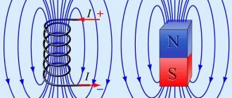
Inductive load (IN)
A load in which the current is phase-shifted back from the voltage by 900 is called inductive. She also consumes Q.
Chain with coil
When an inductor (choke), which has a low active resistance, is connected to an alternating voltage network, an emf is formed in it. Electromotive force opposes applied voltage.
Important! In the case of pure inductance L, the resistance to sinusoidal current increases with increasing frequency. The average power P released by such a load is zero.
Examples of ID are:
- asynchronous motors;
- electromagnets;
- chokes;
- reactors;
- transformers;
- rectifiers
This also includes thyristor converters.
Perform a calculation to determine the forces.
Efforts are precisely the data that helps the engineer understand how the structure feels under the influence of the entire set of loads. If loads (external forces) are what influence the circuit from the outside, then forces are what each element of the design circuit feels directly in its own skin. A person stands on your leg - this is a load applied to your leg as a structure; you felt the pressure of this person’s weight, it causes certain tensions, deformations in you - this is a force in your leg.
One very experienced designer told me that when he checks the solutions of other engineers, he imagines himself in the place of the design. And sometimes he discovers that someone has attached a significant load not to the torso, arms or legs (in general, not to the hardy elements), but has hung it from the ear or nose, or even tried to catch it on the hair. These are jokes, but very deep ones. If you learn to imagine the work of a structure: to imagine in the form of images the forces arising in it from all loads, to imagine its deformations from these efforts, you can significantly make your life easier, and the life of the structure too.
There are not so many types of efforts; they are all collected in two concepts - forces and moments. Effort in the form of force is always direct, it either compresses, stretches, or tries to cut. The force in the form of a moment tries to bend or twist. If you take a rod (beam, column), its “well-being” is very easy to describe with several meanings:
- longitudinal force N, which either compresses or stretches along the axis;
- transverse force Q, which tries to cut the rod across the section (like we cut a carrot with a knife) or at least help it lose stability;
- bending moment M, which tends to bend the rod and bend it;
- torque T, which tries to twist the rod the same way we twist a wet towel.
All these are forces obtained as a result of structural calculations (taken from the typical Lyra example).
It turns out that loads are the initial data for the calculation, and efforts are the result. Why then does there arise confusion in concepts? I think because the efforts found are not the final result, but an intermediate one. Taking into account these efforts, the load-bearing capacity of the section is further checked, reinforcement is calculated and selected. And in this further calculation, efforts take the place of the initial data. And the next stage is emerging for us.
Negative influence of reactive load
Three-phase network power calculation
If we represent the powers in the form of vectors, then the vectors P and Q in sum will give the total power. It is equal to:
S = √ (P2 + Q2).
Total S graph
The formulas for P and Q are:
- P = U*I*sinφ (for a single-phase network) and P = √3* U*I*sinφ (for a three-phase network);
- Q = U*I* cosφ (for a 220 V network) and Q = √3*U*I* cosφ (for a 380 V line).
For your information. Calculations for a three-phase network are correct for symmetrically loaded phases. Otherwise, the powers of all phases are summed up.
The smaller the angle φ between vectors S and P, the higher the power factor cosφ. Complete coincidence of vectors is prevented by Q. The load on power lines and power supply system equipment increases with a large angle value. Overheating of wires and wear of power system equipment occurs.
In practice, the main consumers of manufacturing enterprises are transformers, electric motors and long-distance cables. Therefore, IN is in the lead there, consuming Q. There is an overconsumption of consumed energy, for which enterprises are punished with fines.
Reactive power (RP) carries with it the following disadvantages:
- does not perform useful work;
- causes unnecessary energy consumption and unexpected overload of electrical equipment;
- may cause an emergency.
To compensate for PM, it is necessary to include capacitive elements in parallel with such consumers. For this purpose, Q compensation devices are built. They can be capacitor or inductive, depending on what type of reactive load predominates. Capacitor units, including capacitor batteries, are placed both at power substations and in separate blocks. Such compensation replenishes the reactive component of the energy consumed from the supplier.
Complete condenser unit KKU
Load Definition
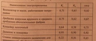
To calculate the total loads and plot them, it is necessary to determine the loads of various parts of the power supply system:
- Powerful electrical receivers (for example, main drives of rolling mills, electric furnaces, powerful electric machines) need to be studied by studying the technological cycle, as well as individual operating mode indicators. Construction of graphs of electrical loads based on technological work schedules of a workshop or enterprise;
- Determine the total abruptly variable loads (for example, electric furnaces, etc.) based on individual load graphs, taking into account the factor of discrepancies between individual graphs to reduce the maximum shock load and to reduce fluctuations in network voltage;
- Determine the load of blower, pumping, compressor stations based on the specific consumption of electrical energy per unit volume of air, water, and so on;
The load of electrical receivers in reserve, welding repair transformers, fire pumps, as well as electrical receivers operating in short-term mode (for example, gate valves, valves, drainage pumps, etc.) is usually not taken into account when calculating average loads. Supply lines and power points must be calculated taking into account the influence of backup power receivers.
Calculation of power by current and voltage
Electric current power formula
You can calculate consumption P by knowing these two parameters I and U of the network. Before choosing cables or wires for wiring in an apartment, you need to decide on the P consumers that can be connected to them. The calculation is made after the measuring instruments record the current readings of the current strength I (A), as well as the voltage U (V).
Single-phase 220 volt network
When connecting an active load to the circuit, use the formula: P = U*I. If there is a phase shift between U and I, use the formula: P = U*I* cosφ.
Three-phase network voltage 380 V
In a three-phase AC network with a phase shift, the result of the last formula is multiplied by √3. The value of the angle cosφ can be clarified in the reference book.
Cosφ table for household devices
When choosing a wire cross-section, the total power of future consumers and the network voltage are usually known.
All you need is the current strength, the formula through power and voltage is:
I = P / (U *cosφ).
The formula for calculating current using power and voltage has the following components:
- P – known power of the device, (W);
- U – supply voltage, (220/380 V);
- cosφ – phase shift angle.
Current calculation can be done using an online calculator.
Online calculator – general view of the interface
Calculation of the cross-section of the power cable and wiring
To ensure safety when operating household electrical appliances, it is necessary to correctly calculate the cross-section of the power cable and wiring. Since an incorrectly selected cable cross-section can lead to overheating of the wire, melting of its insulation and, ultimately, fire due to a short circuit.
Power current voltage, handy cheat sheet
The main parameter used to calculate the wire cross-section is its continuous permissible current load. That is, this is the nominal amount of current that a conductor is capable of passing through itself for a long time. To determine the rated current value, you need to know the approximate power of all connected electrical appliances and equipment in the apartment.
And so what we have:
- The choice of power cable (wire) through which energy-consuming devices can be connected to the network depends on the value of the current.
- Knowing the voltage of the electrical network and the full load of electrical appliances, you can use the formula to calculate the strength of the current that will need to be passed through the conductor (wire, cable). The cross-sectional area of the cores is selected based on its size.
Power at currents: direct and alternating
Calculation of voltage drop in a cable
When it becomes necessary to calculate how much installed equipment will consume, you need to remember that there is a difference between the P value when applying DC and AC voltage.
The formula P for constant current shows P as the product of the instantaneous values of I and U. In this case, the moment in time can be absolutely any.
The expression P under conditions of sinusoidal electron motion takes into account the angle by which the phases of the current and voltage are shifted. The cosine of this angle is multiplied by the product of current and voltage over a period of time T. This is the period of time during which the current changes its value from positive to negative:
T = 1/f, where f is the frequency of 50 Hz.
Features of calculations in alternating electricity circuits
To perform calculations of P, the load consumed in circuits of varying electricity, it is necessary to clearly separate the switching circuits. They can be single-phase or three-phase.
In single-phase circuits, P is found by multiplying the current value by the voltage value (220 V). In this case, the presence of a phase shift between them is taken into account.
In three-phase networks with a voltage of 380 V, two cases are considered:
- symmetrical load per phase;
- asymmetric phase load.
In the first case, P is found using the formula:
P = √3*U*I* cosφ.
In the second case, it is necessary to calculate P for each phase (A, B, C). P value is the result of the summation:
P total = PfA + PfB + PfS.
Attention! When it is necessary to find the total power of a three-phase circuit, the values of reactive Q are found using the same principle.
It is also possible to calculate the current by power, knowing what voltage: phase (220 V) or linear (380 V), by expressing it from the general formula P.
Electric current power
In order to show this what's what, we will take two 12 Volt lamps, but of different power . I also set the power supply to 12 Volts and assemble the whole thing according to the diagram that flashed at the beginning of the article
My power supply can deliver 150 watts to the load without breaking a sweat. I take a light bulb from a moped and attach it to the power supply
Let's look at the current consumption. 0.71 Ampere
We calculate the resistance of the hot filament of a light bulb from Ohm's law I=U/R, hence R=U/I=12/0.71=16.9 Ohm.
I take a halogen lamp from a car headlight and also attach it to the power supply
Let's look at consumption. 4.42 Amps
Similarly, we calculate the resistance of the lamp filament. R=U/I=12/4.42=2.7 Ohm.
Now let’s calculate which light bulb “takes” the most watts from the power source. Let's remember the school formula P=UI. So, for a small light bulb the power will be P=12×0.71=8.52 Watts. And for a large light bulb the power will be P = 12x4.42 = 53 Watts. Wow! We found that the light bulb, which had less resistance, was actually very power-hungry.
So, if anyone doesn’t remember what power is, I can remind you. Power is the ratio of some useful work to the time during which this work was performed. For example, you need to dig a hole of a certain size. You are with a shovel, and your friend is on an excavator:
Who can complete the task faster in the same amount of time? Of course, an excavator. In this case, we can say that his power is much greater than that of a man with a shovel.
Now imagine that we need to completely grind this piece of hardware down to zero:
Think about this question... We have 5 minutes left and we need to sharpen the piece of iron to the maximum. In which case does the piece of iron wear off the fastest: if you press it against the abrasive wheel as hard as you can, press it lightly, or press it half-hard? Don't forget that we have an abrasive wheel attached to a shaft that rotates the flow of water in the pipe. And yes, our pipe is of small diameter.
Whoever answered that if you press half-heartedly turned out to be right. In this case, the piece of iron will wear off faster. If you press it as hard as you can, you can stop the circle altogether. Once again, what is our power? Useful work done over a period of time. And in our experience, useful work is grinding the piece of iron to the maximum speed. Also, do not forget the point that if we lightly press the piece of iron, we will grind it down for half a day. Therefore, the golden mean is to push the piece of iron half-heartedly.
Well, here we go again to electronics.
The flow of water is the current strength, the pressure in the pipe is the voltage, the pressure of the piece of iron on the circle is the resistance. And what did we get as a result? And the fact that a light bulb with less resistance has more power than a light bulb with higher resistance. It’s not hard to guess if you just look at the photo, but the effect is better in real life
But is it necessary that the lower the resistance, the more power is released to the load? Of course not. Everything requires calculation, as in the previous experiment, where we ground down a piece of iron over a certain period of time.
And one more factor, of course, also needs to be taken into account. This is the pressure in the pipe. Just imagine, we sharpen and sharpen a piece of iron, and suddenly the pressure in the pipe began to increase. Maybe the tower overfilled, or someone turned the tap on full blast. What will happen to the emery? Its revolutions will accelerate, as the force of the water flow in the pipe will increase, and therefore, we will grind down our piece of iron even faster.
Calculation of power consumption
The need arises in calculating electrical power when it is necessary to determine how much energy a particular consumer consumes. Or to calculate the load that the room wiring wires must withstand. To select the diameter of the conductor that will be used for wiring, you need to calculate the total power consumption Ppotr of all household appliances simultaneously plugged into the outlet.
Pin = Pnom*T,
Where:
- Pnom – rated power of the device, (W);
- T – operating time of the device, (h).
If an incandescent lamp with Pnom = 60 W operates for four hours during the day, then Pin = Pnom * T = 100*4 = 400 W.
Table for determining Pnom of some household appliances
Collection of loads.
When the design scheme has been determined, when the decision has been made as to what will work in our design and what will “sit on our neck,” we should understand as thoroughly as possible what affects our design. And here we first encounter the concept of “load”. Load is any external influence that affects our structure. The list of loads is not that long:
- Load from its own weight (yes, even under its own weight an incorrectly calculated structure can break) and from the weight of other elements and materials.
- The load from the weight of people, furniture, equipment - in general, everything that may or may not exist, but it is important to take this into account and not miscalculate.
- Snow load.
- Wind load.
- Load from temperature influences (under the influence of temperatures, materials expand to the point of destruction; this phenomenon can also be expressed in the form of load).
- Seismic load.
As you can see, all this (well, with the exception of its own weight) comes from the outside, but has a significant impact on any design. Moreover, each load can be located in space in an arbitrary manner in relation to the calculation object - perpendicular, and at an angle, and along the axis. Loads can be combined with each other or exclude each other. In general, there are a lot of options, but we need to combine all this into a single system, find the worst option and design a structure that can bear this worst option on its own shoulders. What method is used in calculations to convert loads into a digestible format? After all, there can be a lot of loads, but looking at them, it is not immediately possible to understand whether they have a bad or good effect on the structure. It is to clarify the picture with loads that the calculation algorithm contains the next, very important step.
Calculation of electrical circuits
All formulas used to calculate electrical circuits follow from one another.
Electrical characteristics relationships
So, for example, using the formula for calculating power, you can calculate the current strength if P and U are known.
To find out how much current an iron (1100 W) connected to a 220 V network will consume, you need to express the current strength from the power formula:
I = P/U = 1100/220 = 5 A.
Knowing the calculated resistance of the electric stove spiral, you can find P of the device. Power through resistance is determined by the formula:
P = U2/R.
There are several methods that allow you to solve the problems of calculating various parameters of a given circuit.
Methods for calculating electrical circuits
Calculating power for various types of current circuits helps to correctly assess the condition of power lines. Household and industrial devices selected in accordance with the specified parameters Pnom and S will work reliably and withstand maximum loads for years.