Basic properties and characteristics of the magnetic field.
Electromagnetism
A magnetic field
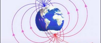
- this is matter that arises around sources of electric current, as well as around permanent magnets (Fig. 1.1). In space, the magnetic field is displayed as a combination of forces that can influence magnetized bodies. This action is explained by the presence of driving discharges at the molecular level.
Rice.
1.1 A magnetic field is formed only around electric charges that are in motion. That is why the magnetic and electric fields are integral and together form the electromagnetic field
. The components of the magnetic field are interconnected and influence each other, changing their properties.
Properties of magnetic field:
1. A magnetic field arises under the influence of driving charges of electric current.
2. At any point, a magnetic field is characterized by a vector of a physical quantity called magnetic induction
, which is a force characteristic of a magnetic field. 3. A magnetic field can only affect magnets, current-carrying conductors and moving charges. 4. The magnetic field can be of a constant or variable type 5. The magnetic field is measured only by special instruments and cannot be perceived by human senses. 6. The magnetic field is electrodynamic, since it is generated only by the movement of charged particles and affects only charges that are in motion. 7. Charged particles move along a perpendicular trajectory.
The size of the magnetic field depends on the rate of change of the magnetic field. According to this feature, there are two types of magnetic field: dynamic magnetic
field
and
gravitational magnetic field
.
The gravitational magnetic field
arises only near elementary particles and is formed depending on the structural features of these particles.
A magnetic moment occurs when a magnetic field acts on a conductive frame.
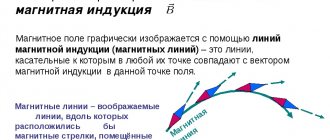
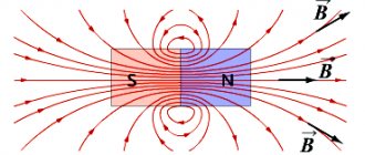
In other words, the magnetic moment is a vector that is located on the line that runs perpendicular to the frame. The magnetic field can be represented graphically using magnetic field lines. These lines are drawn in such a direction that the direction of the field forces coincides with the direction of the field line itself. Magnetic lines of force are continuous and closed at the same time.
The direction of the magnetic field is determined using a magnetic needle. The lines of force also determine the polarity of the magnet, the end with the output of the force lines is the north pole, and the end with the input of these lines is the south pole.
It is very convenient to visually evaluate the magnetic field using ordinary iron filings and a piece of paper. If we put a sheet of paper on a permanent magnet and sprinkle sawdust on top, then the iron particles will line up according to the magnetic field lines.
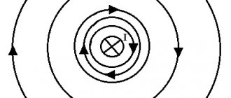
The direction of the power lines for a conductor is conveniently determined by the famous gimlet rule
or
the right hand rule
(Fig. 1.2)
.
If we wrap our hand around the conductor so that the thumb points in the direction of the current (from plus to minus), then the 4 remaining fingers will show us the direction of the magnetic field lines.
Rice. 1.2
· Ampere's law
Ampere's law
shows the force with which a magnetic field acts on a conductor placed in it. This force is also called the Ampere force.
Statement of the law: the force acting on a current-carrying conductor placed in a uniform magnetic field is proportional to the length of the conductor, the magnetic induction vector, the current strength and the sine of the angle between the magnetic induction vector and the conductor.
The energy contained in a magnetic field can manifest itself in the form of electromagnetic forces, which arise when the magnetic field interacts with moving electric charges
50
If you place a conductor with current I in a magnetic field, then electromagnetic forces will arise between the electrons passing through the conductor and the magnetic field, which, adding up, form a resultant force F, tending to push the conductor out of the magnetic field. The electromagnetic force F acting on a current-carrying conductor located in a magnetic field and located perpendicular to the direction of the field is equal to the product of the current strength I, the magnetic field induction B and the length of the conductor:
.
If the conductor is located at an angle α to the magnetic force, then the force, N,
.
The direction of action of force F is usually determined by the left-hand rule (Fig. 1.3).
Rice. 1.3
As a result of the influence of such mechanical forces, with the same direction of current, adjacent conductors will be attracted to each other (Fig. 1.4, a), with different directions of current, they will repel (Fig. 1.4, b). The design of various electrical machines and instruments, for example, measuring instruments of a magnetoelectric system, is based on the phenomenon of interaction of a magnetic field and a conductor with current. Particularly large forces between conductors arise in electrical circuits during short circuits.
a) b)
Rice. 1.4 Interaction of two conductors with current: a) with the same direction of the current; b) with different directions of current
· Characteristics of the magnetic field
Magnetic induction. The intensity of a magnetic field is characterized by magnetic induction B. The stronger the magnetic field created by a permanent magnet or electromagnet, the greater the induction it has. The direction of action of the electromagnetic force F on the conductor is determined by the left-hand rule (Fig. 1.3).
If you position your left hand so that the magnetic lines penetrate the palm, and the extended four fingers indicate the direction of the current in the conductor, then the bent thumb will indicate the direction of the electromagnetic force.
By this force one can judge the intensity of the magnetic field, i.e. its magnetic induction. If a 1 m long conductor with a current of 1 A, located perpendicular to the magnetic lines in a uniform magnetic field, is acted upon by a force of 1 N, then the magnetic induction of such a field is equal to 1 T (tesla).
Magnetic induction
is a vector quantity
: at each point in the field, the magnetic induction vector is directed tangentially to the magnetic lines of force.
Magnetic flux. The quantity measured by the product of magnetic induction B and area S perpendicular to the magnetic induction vector is called magnetic flux Ф:
F=BS.
Magnetic induction is expressed in teslas, and area is expressed in square meters, so the unit of magnetic flux is weber:
1 Wb = 1 T ∙ 1
Magnetomotive force
.
The ability of a current to excite a magnetic field is characterized by a magnetomotive force (MF)
acting along a closed magnetic field line. Magnetomotive force is equal to the current creating a magnetic field and is expressed in amperes.
For a conductor with current I, the MMF is equal to the current I. In the general case, when a closed loop of a magnetic field line covers several currents, the total MMF is equal to the sum of the currents.
For a coil with the number of turns w and current I (Fig. 1.5), the MMF is equal to
ƩI=Iw.
Magnetic field strength
.
The magnetomotive force per unit length of a magnetic field line is called magnetic
field strength H and is expressed in amperes per meter (A/m).
If the physical conditions along the entire length I of the magnetic line are the same, then
.
For example, around a straight conductor with current I, the magnetic field lines are concentric circles of variable radius x, the length of each of which is I = 2 x. In this case, tension.
.
As you move away from the conductor, the field strength decreases.
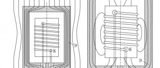
Rice. 1.5. Toroidal coil
Magnetic permeability
.
Magnetic induction depends not only on the strength of the current passing through a straight conductor or inductive coil, but also on the properties of the medium in which the magnetic field is created. The quantity characterizing the magnetic properties of a medium is absolute magnetic permeability
. It is determined by the ratio of magnetic induction B to magnetic field strength H and is measured in henry per meter (H/m):
.
Absolute magnetic permeability of vacuum = 4π ∙ H/m. For air and other non-ferromagnetic materials, it differs slightly from the magnetic permeability of vacuum and for technical calculations is taken equal to 4π ∙ H/m. Since the absolute magnetic permeability for vacuum and the previously mentioned materials is almost the same, it is called the magnetic constant
.
The absolute magnetic permeability of ferromagnetic materials is not constant and is many times higher than the magnetic permeability of vacuum. The number indicating how many times the absolute magnetic permeability of a ferromagnetic material is greater than the magnetic constant is called relative magnetic permeability
, or (abbreviated) magnetic permeability:
.
Magnetic properties of matter
Permanent magnets can be made from only relatively few substances, but all substances placed in a magnetic field are magnetized, that is, they themselves become sources of a magnetic field. As a result, the magnetic induction vector in the presence of matter differs from the magnetic induction vector in a vacuum.
Definition
Magnetic permeability of a substance
μ shows how many times the magnetic induction vector in a substance is greater than the magnetic induction vector in a vacuum, that is
=μ⋅
The magnetic properties of a substance are determined by how these substances react to an external magnetic field and how their internal structure is ordered. There are three main classes of substances with sharply different magnetic properties: ferromagnetic, paramagnetic and diamagnetic.
Substances that, like iron, have μ≫1, are called ferromagnets
.
The most important property of ferromagnets is the existence of residual magnetism. Permanent magnets are made from ferromagnets.
However, when heated to a sufficiently high temperature, the ferromagnetic properties of bodies disappear (Curie point).
The temperature at which a substance loses its ferromagnetic properties is called the temperature or Curie point
.
| Iron (Fe) | 77 C |
| Nickel (Ni) | 36 C |
| Cobalt (Co) | 100 C |
When a permanent magnet is heated above this temperature, it stops attracting iron objects. The magnetic permeability of ferromagnets is not constant; it depends on the magnetic induction of the external field.
There are substances that behave like iron, i.e. are drawn into a magnetic field. These substances are called paramagnetic
. They have μ>1, but differ from unity by an amount of the order of .
The magnetic permeability of paramagnetic materials depends on temperature and decreases as it increases. Without a magnetizing field, paramagnetic materials do not create their own magnetic field. There are no permanent paramagnets.
Diamagnets
- substances that are pushed out of a magnetic field. For diamagnetic materials, μ<1 differs from unity by an amount of the order of .
Magnetic permeability is practically independent of the magnetizing field induction and temperature. When a diamagnetic material is removed from an external magnetizing field, it is completely demagnetized and does not create a magnetic field.
Superconductors are ideal diamagnets. The magnetic field does not penetrate into the superconductor at all. This means that a superconductor is an ideal diamagnetic. Since the magnetic induction inside the conductor is zero, then according to the formula =μ⋅ the magnetic permeability μ of the superconductor is also zero.
· Magnetization of a ferromagnet. Magnetization stages.
The magnetization of ferromagnets is a process consisting of several stages.
At the first stage, as the strength of the external magnetic field increases, the sizes of those domains whose own magnetic moment forms an acute angle with the external field increase. At the same time, the volume of those domains for which this angle is obtuse decreases.
______________________________
* Typically the domain dimensions are 10-4...10-5 m.
By the end of the first stage, domains in which the mentioned angle is acute completely absorb those in which the angle between their own and external magnetic fields is obtuse.
This magnetization stage is called the boundary displacement stage.
At the second stage, a further increase in the strength of the external magnetic field causes the magnetic moments of the domains to rotate towards the external magnetic field.
The second stage of magnetization is called the rotation stage.
By the end of the second stage, the magnetic moments of all domains are directed along the external magnetic field. At the end of this stage, the third stage of magnetization begins - the saturation stage.
During the first and second stages of magnetization, the field inside the ferromagnet grows due to an increase in both the external magnetic field and the magnetic field created by the domains.
At the third stage, the increase in the magnetic field in the ferromagnet occurs only due to the increase in the external magnetic field. The total magnetic field of the domains does not change.
· Hysteresis phenomenon
If we reduce the magnetic field that caused the magnetization of the ferromagnet, it turns out that the dependence of the magnetic field induction in the ferromagnet on the strength of the external magnetic field does not coincide with the initial magnetization curve.
When the external magnetic field strength decreases to zero, the magnetic field in the ferromagnet will not decrease to zero. The magnetic field induction in a ferromagnet will be equal to B
ost – residual field induction in a ferromagnet. In other words, the ferromagnetic sample will remain magnetized after turning off the external magnetic field.
In order to reduce the magnetic field induction in a ferromagnet to zero, it is necessary to change the direction of the external magnetic field to the opposite and begin to gradually increase its intensity.
At some tension N
c the field induction in the ferromagnet will decrease to zero.
This tension is usually called coercive force
.
A further increase in voltage causes magnetization of the ferromagnet. The direction of magnetization is opposite to the original one.
If, after magnetization to saturation, the strength of the external magnetic field is again reduced, then the process will proceed as shown in the figure.
Dependency graph B
(
H
) will close, forming a so-called
hysteresis loop
.
The phenomenon under consideration is called the phenomenon of hysteresis.
The phenomenon of hysteresis is that the value of B
for a given
H
depends on what value
H
had previously.
For example, if a ferromagnet is not magnetized, then at H
= 0
V
= 0.
If the ferromagnet was previously in a magnetic field with H
>0, then when
N
= 0
V
=
V
ost
If previously the tension was negative, then at N
= 0
V
=-
V
ost
Ferromagnets are divided into two groups. The basis for classification is the coercive force.
Coercive force measures how difficult it is to demagnetize a ferromagnet. If the coercive force is high, then it is difficult to demagnetize the ferromagnet. Such ferromagnets are called magnetically hard.
. Permanent magnets are made from hard ferromagnets.
If the coercive force is small, the ferromagnet can be demagnetized with almost no energy expended. Such ferromagnets are called soft magnetic.
Transformer cores are made from them.
Control questions
1. Can a magnetic field exist independent of an electric field?
2. What rule determines the directions of magnetic field lines?
3. In what units is magnetic induction measured?
4. What parameters does magnetic induction depend on?
4. What is called relative magnetic permeability c?
Electromagnetism
A magnetic field
- this is matter that arises around sources of electric current, as well as around permanent magnets (Fig. 1.1).
In space, the magnetic field is displayed as a combination of forces that can influence magnetized bodies. This action is explained by the presence of driving discharges at the molecular level. Rice.
1.1 A magnetic field is formed only around electric charges that are in motion. That is why the magnetic and electric fields are integral and together form the electromagnetic field
. The components of the magnetic field are interconnected and influence each other, changing their properties.
Properties of magnetic field:
1. A magnetic field arises under the influence of driving charges of electric current.
2. At any point, a magnetic field is characterized by a vector of a physical quantity called magnetic induction
, which is a force characteristic of a magnetic field. 3. A magnetic field can only affect magnets, current-carrying conductors and moving charges. 4. The magnetic field can be of a constant or variable type 5. The magnetic field is measured only by special instruments and cannot be perceived by human senses. 6. The magnetic field is electrodynamic, since it is generated only by the movement of charged particles and affects only charges that are in motion. 7. Charged particles move along a perpendicular trajectory.
The size of the magnetic field depends on the rate of change of the magnetic field. According to this feature, there are two types of magnetic field: dynamic magnetic
field
and
gravitational magnetic field
.
The gravitational magnetic field
arises only near elementary particles and is formed depending on the structural features of these particles.
A magnetic moment occurs when a magnetic field acts on a conductive frame.
In other words, the magnetic moment is a vector that is located on the line that runs perpendicular to the frame. The magnetic field can be represented graphically using magnetic field lines. These lines are drawn in such a direction that the direction of the field forces coincides with the direction of the field line itself. Magnetic lines of force are continuous and closed at the same time.
The direction of the magnetic field is determined using a magnetic needle. The lines of force also determine the polarity of the magnet, the end with the output of the force lines is the north pole, and the end with the input of these lines is the south pole.
It is very convenient to visually evaluate the magnetic field using ordinary iron filings and a piece of paper. If we put a sheet of paper on a permanent magnet and sprinkle sawdust on top, then the iron particles will line up according to the magnetic field lines.
The direction of the power lines for a conductor is conveniently determined by the famous gimlet rule
or
the right hand rule
(Fig. 1.2)
.
If we wrap our hand around the conductor so that the thumb points in the direction of the current (from plus to minus), then the 4 remaining fingers will show us the direction of the magnetic field lines.
Rice. 1.2
· Ampere's law
Ampere's law
shows the force with which a magnetic field acts on a conductor placed in it. This force is also called the Ampere force.
Statement of the law: the force acting on a current-carrying conductor placed in a uniform magnetic field is proportional to the length of the conductor, the magnetic induction vector, the current strength and the sine of the angle between the magnetic induction vector and the conductor.
The energy contained in a magnetic field can manifest itself in the form of electromagnetic forces, which arise when the magnetic field interacts with moving electric charges
50
If you place a conductor with current I in a magnetic field, then electromagnetic forces will arise between the electrons passing through the conductor and the magnetic field, which, adding up, form a resultant force F, tending to push the conductor out of the magnetic field. The electromagnetic force F acting on a current-carrying conductor located in a magnetic field and located perpendicular to the direction of the field is equal to the product of the current strength I, the magnetic field induction B and the length of the conductor:
.
If the conductor is located at an angle α to the magnetic force, then the force, N,
.
The direction of action of force F is usually determined by the left-hand rule (Fig. 1.3).
Rice. 1.3
As a result of the influence of such mechanical forces, with the same direction of current, adjacent conductors will be attracted to each other (Fig. 1.4, a), with different directions of current, they will repel (Fig. 1.4, b). The design of various electrical machines and instruments, for example, measuring instruments of a magnetoelectric system, is based on the phenomenon of interaction of a magnetic field and a conductor with current. Particularly large forces between conductors arise in electrical circuits during short circuits.
a) b)
Rice. 1.4 Interaction of two conductors with current: a) with the same direction of the current; b) with different directions of current
· Characteristics of the magnetic field
Magnetic induction. The intensity of a magnetic field is characterized by magnetic induction B. The stronger the magnetic field created by a permanent magnet or electromagnet, the greater the induction it has. The direction of action of the electromagnetic force F on the conductor is determined by the left-hand rule (Fig. 1.3).
If you position your left hand so that the magnetic lines penetrate the palm, and the extended four fingers indicate the direction of the current in the conductor, then the bent thumb will indicate the direction of the electromagnetic force.
By this force one can judge the intensity of the magnetic field, i.e. its magnetic induction. If a 1 m long conductor with a current of 1 A, located perpendicular to the magnetic lines in a uniform magnetic field, is acted upon by a force of 1 N, then the magnetic induction of such a field is equal to 1 T (tesla).
Magnetic induction
is a vector quantity
: at each point in the field, the magnetic induction vector is directed tangentially to the magnetic lines of force.
Magnetic flux. The quantity measured by the product of magnetic induction B and area S perpendicular to the magnetic induction vector is called magnetic flux Ф:
F=BS.
Magnetic induction is expressed in teslas, and area is expressed in square meters, so the unit of magnetic flux is weber:
1 Wb = 1 T ∙ 1
Magnetomotive force
.
The ability of a current to excite a magnetic field is characterized by a magnetomotive force (MF)
acting along a closed magnetic field line. Magnetomotive force is equal to the current creating a magnetic field and is expressed in amperes.
For a conductor with current I, the MMF is equal to the current I. In the general case, when a closed loop of a magnetic field line covers several currents, the total MMF is equal to the sum of the currents.
For a coil with the number of turns w and current I (Fig. 1.5), the MMF is equal to
ƩI=Iw.
Magnetic field strength
.
The magnetomotive force per unit length of a magnetic field line is called magnetic
field strength H and is expressed in amperes per meter (A/m).
If the physical conditions along the entire length I of the magnetic line are the same, then
.
For example, around a straight conductor with current I, the magnetic field lines are concentric circles of variable radius x, the length of each of which is I = 2 x. In this case, tension.
.
As you move away from the conductor, the field strength decreases.
Rice. 1.5. Toroidal coil
Magnetic permeability
.
Magnetic induction depends not only on the strength of the current passing through a straight conductor or inductive coil, but also on the properties of the medium in which the magnetic field is created. The quantity characterizing the magnetic properties of a medium is absolute magnetic permeability
. It is determined by the ratio of magnetic induction B to magnetic field strength H and is measured in henry per meter (H/m):
.
Absolute magnetic permeability of vacuum = 4π ∙ H/m. For air and other non-ferromagnetic materials, it differs slightly from the magnetic permeability of vacuum and for technical calculations is taken equal to 4π ∙ H/m. Since the absolute magnetic permeability for vacuum and the previously mentioned materials is almost the same, it is called the magnetic constant
.
The absolute magnetic permeability of ferromagnetic materials is not constant and is many times higher than the magnetic permeability of vacuum. The number indicating how many times the absolute magnetic permeability of a ferromagnetic material is greater than the magnetic constant is called relative magnetic permeability
, or (abbreviated) magnetic permeability:
.
Magnetic properties of matter
Permanent magnets can be made from only relatively few substances, but all substances placed in a magnetic field are magnetized, that is, they themselves become sources of a magnetic field. As a result, the magnetic induction vector in the presence of matter differs from the magnetic induction vector in a vacuum.
Definition
Magnetic permeability of a substance
μ shows how many times the magnetic induction vector in a substance is greater than the magnetic induction vector in a vacuum, that is
=μ⋅
The magnetic properties of a substance are determined by how these substances react to an external magnetic field and how their internal structure is ordered. There are three main classes of substances with sharply different magnetic properties: ferromagnetic, paramagnetic and diamagnetic.
Substances that, like iron, have μ≫1, are called ferromagnets
.
The most important property of ferromagnets is the existence of residual magnetism. Permanent magnets are made from ferromagnets.
However, when heated to a sufficiently high temperature, the ferromagnetic properties of bodies disappear (Curie point).
The temperature at which a substance loses its ferromagnetic properties is called the temperature or Curie point
.
| Iron (Fe) | 77 C |
| Nickel (Ni) | 36 C |
| Cobalt (Co) | 100 C |
When a permanent magnet is heated above this temperature, it stops attracting iron objects. The magnetic permeability of ferromagnets is not constant; it depends on the magnetic induction of the external field.
There are substances that behave like iron, i.e. are drawn into a magnetic field. These substances are called paramagnetic
. They have μ>1, but differ from unity by an amount of the order of .
The magnetic permeability of paramagnetic materials depends on temperature and decreases as it increases. Without a magnetizing field, paramagnetic materials do not create their own magnetic field. There are no permanent paramagnets.
Diamagnets
- substances that are pushed out of a magnetic field. For diamagnetic materials, μ<1 differs from unity by an amount of the order of .
Magnetic permeability is practically independent of the magnetizing field induction and temperature. When a diamagnetic material is removed from an external magnetizing field, it is completely demagnetized and does not create a magnetic field.
Superconductors are ideal diamagnets. The magnetic field does not penetrate into the superconductor at all. This means that a superconductor is an ideal diamagnetic. Since the magnetic induction inside the conductor is zero, then according to the formula =μ⋅ the magnetic permeability μ of the superconductor is also zero.
· Magnetization of a ferromagnet. Magnetization stages.
The magnetization of ferromagnets is a process consisting of several stages.
At the first stage, as the strength of the external magnetic field increases, the sizes of those domains whose own magnetic moment forms an acute angle with the external field increase. At the same time, the volume of those domains for which this angle is obtuse decreases.
______________________________
* Typically the domain dimensions are 10-4...10-5 m.
By the end of the first stage, domains in which the mentioned angle is acute completely absorb those in which the angle between their own and external magnetic fields is obtuse.
This magnetization stage is called the boundary displacement stage.
At the second stage, a further increase in the strength of the external magnetic field causes the magnetic moments of the domains to rotate towards the external magnetic field.
The second stage of magnetization is called the rotation stage.
By the end of the second stage, the magnetic moments of all domains are directed along the external magnetic field. At the end of this stage, the third stage of magnetization begins - the saturation stage.
During the first and second stages of magnetization, the field inside the ferromagnet grows due to an increase in both the external magnetic field and the magnetic field created by the domains.
At the third stage, the increase in the magnetic field in the ferromagnet occurs only due to the increase in the external magnetic field. The total magnetic field of the domains does not change.
· Hysteresis phenomenon
If we reduce the magnetic field that caused the magnetization of the ferromagnet, it turns out that the dependence of the magnetic field induction in the ferromagnet on the strength of the external magnetic field does not coincide with the initial magnetization curve.
When the external magnetic field strength decreases to zero, the magnetic field in the ferromagnet will not decrease to zero. The magnetic field induction in a ferromagnet will be equal to B
ost – residual field induction in a ferromagnet. In other words, the ferromagnetic sample will remain magnetized after turning off the external magnetic field.
In order to reduce the magnetic field induction in a ferromagnet to zero, it is necessary to change the direction of the external magnetic field to the opposite and begin to gradually increase its intensity.
At some tension N
c the field induction in the ferromagnet will decrease to zero.
This tension is usually called coercive force
.
A further increase in voltage causes magnetization of the ferromagnet. The direction of magnetization is opposite to the original one.
If, after magnetization to saturation, the strength of the external magnetic field is again reduced, then the process will proceed as shown in the figure.
Dependency graph B
(
H
) will close, forming a so-called
hysteresis loop
.
The phenomenon under consideration is called the phenomenon of hysteresis.
The phenomenon of hysteresis is that the value of B
for a given
H
depends on what value
H
had previously.
For example, if a ferromagnet is not magnetized, then at H
= 0
V
= 0.
If the ferromagnet was previously in a magnetic field with H
>0, then when
N
= 0
V
=
V
ost
If previously the tension was negative, then at N
= 0
V
=-
V
ost
Ferromagnets are divided into two groups. The basis for classification is the coercive force.
Coercive force measures how difficult it is to demagnetize a ferromagnet. If the coercive force is high, then it is difficult to demagnetize the ferromagnet. Such ferromagnets are called magnetically hard.
. Permanent magnets are made from hard ferromagnets.
If the coercive force is small, the ferromagnet can be demagnetized with almost no energy expended. Such ferromagnets are called soft magnetic.
Transformer cores are made from them.
Control questions
1. Can a magnetic field exist independent of an electric field?
2. What rule determines the directions of magnetic field lines?
3. In what units is magnetic induction measured?
4. What parameters does magnetic induction depend on?
4. What is called relative magnetic permeability c?
Magnetic interaction
French physicist Andre-Marie Ampère discovered in 1820 that two conductors carrying an electric current, located parallel to each other, attract if the directions of the currents coincide, and repel if the currents are directed in different directions. Ampere called this effect electrodynamic interaction.
Rice. 1. Ampere’s experience on the interaction of currents in parallel conductors.
To explain this phenomenon, Ampere introduced the concept of a magnetic field that arises around any moving electric charge. The magnetic field is continuous in space and manifests itself by exerting a force on other moving electric charges.
Ampere's predecessors tried to build a theory of the magnetic field by analogy with the electric field using magnetic charges with different signs (northern N and southern S). However, experiments have shown that separate magnetic charges do not exist in nature. A magnetic field arises only as a result of the movement of electric charges.
Magnetic force
The force acting on a current-carrying conductor from the magnetic field was named after the discoverer - the Ampere force. Experiments have shown that the ampere force modulus F is proportional to the length of the conductor L and depends on the spatial position of the conductor in the magnetic field.
To quantitatively describe the effect of a magnetic field on a current-carrying conductor, a quantity called magnetic induction B was introduced. Then the Ampere force will be equal to:
$F = B*I*L$ (1),
where I is the current strength. This formula is valid when calculating the modulus of the maximum value of the Ampere force acting on a straight conductor in a magnetic field; the magnetic field vector B is directed at 900 to the current vector I.
If the conductor is located at an angle α to the magnetic induction vector B, then instead of formula (1) the following formula should be used:
$F = B*I*L*sinα$ (2).