Author: Evgeny Zhivoglyadov. Date of publication: August 09, 2013. Category: Articles.
If you bring a magnetic needle to a straight conductor carrying an electric current, it will tend to become perpendicular to the plane passing through the axis of the conductor and the center of rotation of the needle. This indicates that the needle is subject to special forces called magnetic forces . In addition to the effect on the magnetic needle, the magnetic field affects moving charged particles and current-carrying conductors located in the magnetic field. In conductors moving in a magnetic field, or in stationary conductors located in an alternating magnetic field, an inductive electromotive force (emf) arises.
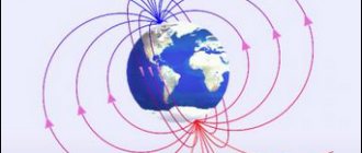
A magnetic field
In accordance with the above, we can give the following definition of a magnetic field.
A magnetic field is one of the two sides of the electromagnetic field, excited by the electric charges of moving particles and changes in the electric field and characterized by a force effect on moving infected particles, and therefore on electric currents.
| Figure 1. Magnetic field around a current-carrying conductor |
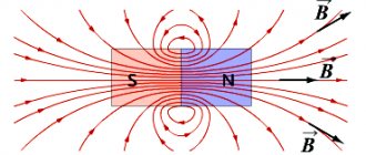
| Figure 2. Direction of magnetic induction lines |
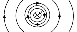
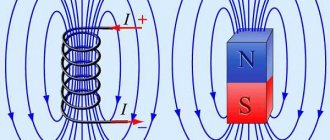
If you pass a thick conductor through cardboard and pass an electric current through it, then the steel filings poured onto the cardboard will be located around the conductor in concentric circles, which in this case are the so-called magnetic induction lines (Figure 1). We can move the cardboard up or down the conductor, but the location of the steel filings will not change. Consequently, a magnetic field arises around the conductor along its entire length.
If you put small magnetic arrows on the cardboard, then by changing the direction of the current in the conductor, you can see that the magnetic arrows will rotate (Figure 2). This shows that the direction of magnetic induction lines changes with the direction of current in the conductor.
Magnetic induction lines around a current-carrying conductor have the following properties: 1) magnetic induction lines of a straight conductor have the shape of concentric circles; 2) the closer to the conductor, the denser the magnetic induction lines are located; 3) magnetic induction (field intensity) depends on the magnitude of the current in the conductor; 4) the direction of magnetic induction lines depends on the direction of the current in the conductor.
To show the direction of the current in the conductor shown in section, a symbol has been adopted, which we will use in the future. If you mentally place an arrow in the conductor in the direction of the current (Figure 3), then in the conductor in which the current is directed away from us, we will see the tail of the arrow’s feathers (a cross); if the current is directed towards us, we will see the tip of an arrow (point).
Figure 3. Symbol for the direction of current in conductors
Direction of current and direction of magnetic field lines
Gimlet rule
Previously, a magnet arrow was used to determine the direction of the magnetic field in experiments. But what to do if you don’t have it at hand?
You need to know the rule of the gimlet* (right screw): when the translational movement of the gimlet (screw) is in the same direction as the current flowing in the conductor, the direction of rotation of the gimlet handle will indicate the direction of the magnetic field lines.
Figure 7 provides an illustration of how to use the gimlet rule. Relative to the reader, the current flows downward. The gimlet, located as in the figure, is rotated clockwise so that it moves down. Then, in accordance with the rule, the direction of the magnetic lines around the conductor is “clockwise”.
Figure 7 – Illustration of using the gimlet rule
*Reminder: In general, a gimlet is a cutting tool for drilling small holes. However, it is often difficult for schoolchildren to imagine it. A simpler example of a system similar to a gimlet is a regular stopper on a plastic bottle. When the bottle is positioned vertically and the cap is twisted clockwise, it moves progressively downward. If the plug is untwisted counterclockwise, it will move upward. You can use this example as a guide, mentally positioning the bottle with the stopper vertically or horizontally to make it easier to use the gimlet rule in the future.
Instead of a gimlet, the rule of the right hand is often used: if the thumb bent 90° from the palm is turned along the current in the conductor, and then the remaining fingers clasp the conductor, they will indicate the direction of the magnetic field lines.
An example explaining the right-hand rule is shown in Figure 8.
Figure 8 – Illustration of the application of the right hand rule
The gimlet rules and the right hand rules are equally convenient and you can use either of them. However, further we will also consider the left-hand rule. To avoid confusion about which situation to use which hand, it is preferable to use the gimlet rule to determine the direction of the magnetic field lines.
Gimlet rule
The gimlet rule allows you to determine the direction of magnetic induction lines around a current-carrying conductor. If a gimlet (corkscrew) with a right-hand thread moves forward in the direction of the current, then the direction of rotation of the handle will coincide with the direction of the magnetic induction lines around the conductor (Figure 4).
A magnetic needle introduced into the magnetic field of a current-carrying conductor is located along the magnetic induction lines. Therefore, to determine its location, you can also use the “gimlet rule” (Figure 5). The magnetic field is one of the most important manifestations of electric current and cannot be obtained independently and separately from the current.
| Figure 4. Determining the direction of magnetic induction lines around a current-carrying conductor using the “gimlet rule” | Figure 5. Determining the direction of deviation of a magnetic needle brought to a conductor with current, according to the “gimlet rule” |
Magnetic induction
A magnetic field is characterized by a magnetic induction vector, which therefore has a certain magnitude and a certain direction in space.
| Figure 6. To Biot and Savart's law |
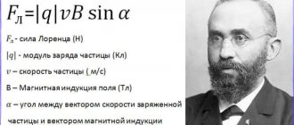
A quantitative expression for magnetic induction as a result of generalization of experimental data was established by Biot and Savart (Figure 6). Measuring the magnetic fields of electric currents of various sizes and shapes by the deflection of the magnetic needle, both scientists came to the conclusion that every current element creates a magnetic field at some distance from itself, the magnetic induction of which ΔB is directly proportional to the length Δl of this element, the magnitude of the flowing current I, sine angle α between the direction of the current and the radius vector connecting the field point of interest to us with a given current element, and is inversely proportional to the square of the length of this radius vector r:
where K is a coefficient depending on the magnetic properties of the medium and the chosen system of units.
In the absolute practical rationalized system of units of ICSA
where µ0 is the magnetic permeability of vacuum or the magnetic constant in the MCSA system:
µ0 = 4 × π × 10-7 (henry/meter);
henry (hn) – unit of inductance; 1 gn = 1 ohm × sec.
µ – relative magnetic permeability – a dimensionless coefficient showing how many times the magnetic permeability of a given material is greater than the magnetic permeability of vacuum.
The dimension of magnetic induction can be found using the formula
Volt-second is otherwise called Weber (vb):
In practice, there is a smaller unit of magnetic induction - gauss (gs):
Biot-Savart's law allows us to calculate the magnetic induction of an infinitely long straight conductor:
where a is the distance from the conductor to the point where the magnetic induction is determined.
Basic formulas for calculating the MI vector
The magnetic induction vector, the formula of which is B = Fm/I*∆L, can be found using other mathematical calculations.
Biot-Savart-Laplace Law
Induction EMF formula
Describes the rules for finding B→ magnetic field, which creates a constant electric current. This is an experimentally established pattern. Biot and Savard identified it in practice in 1820, Laplace managed to formulate it. This law is fundamental in magnetostatics. During the practical experiment, a stationary wire with a small cross-section was considered, through which an electric current was passed. For study, a small section of wire was selected, which was characterized by the vector dl. Its module corresponded to the length of the section under consideration, and its direction coincided with the direction of the current.
Interesting. Laplace Pierre Simon proposed to consider even the movement of one electron as a current and, based on this statement, using this law, he proved the possibility of determining the magnetic field of an advancing point charge.
According to this physical rule, each segment dl of a conductor through which electric current I flows forms a magnetic field dB in the space around itself at an interval r and at an angle α:
dB = µ0 *I*dl*sin α /4*π*r2,
Where:
- dB – magnetic induction, T;
- µ0 = 4 π*10-7 – magnetic constant, H/m;
- I – current strength, A;
- dl – conductor section, m;
- r – distance to the point where the magnetic induction is located, m;
- α is the angle formed by r and the vector dl.
Important! According to the Biot-Savart-Laplace law, by summing the magnetic field vectors of individual sectors, it is possible to determine the MF of the desired current. It will be equal to the vector sum.
Biot-Savart-Laplace Law
There are formulas that describe this law for individual cases of MP:
- fields of direct movement of electrons;
- fields of circular motion of charged particles.
The formula for MP of the first type is:
B = µ* µ0*2*I/4*π*r.
For circular motion it looks like this:
B = µ*µ0*I/4*π*r.
In these formulas, µ is the magnetic permeability of the medium (relative).
The law under consideration follows from Maxwell's equations. Maxwell derived two equations for the magnetic field; the case where the electric field is constant is considered by Biot and Savart.
Superposition principle
For MF, there is a principle according to which the total vector of magnetic induction at a certain point is equal to the vector sum of all MI vectors created by different currents at a given point:
B→= B1→+ B2→+ B3→… + Bn→
Superposition principle
Circulation theorem
Initially, in 1826, Andre Ampère formulated this theorem. He analyzed the case with constant electric fields, his theorem is applicable to magnetostatics. The theorem states: the circulation of MF of direct electricity along any circuit is proportional to the sum of the forces of all currents that penetrate this circuit.
Worth knowing! Thirty-five years later, D. Maxwell generalized this statement, drawing parallels with hydrodynamics.
Another name for the theorem is Ampere’s law, which describes the circulation of MP.
Mathematically, the theorem is written as follows.
Mathematical formula of the circulation theorem
Where:
- B→– magnetic induction vector;
- j→ – electron motion density.
This is the integral form of writing the theorem. Here, on the left side one integrates along a certain closed contour, on the right side - along a stretched surface onto the resulting contour.
It will be interesting➡ What is static electricity and how to get rid of it. What causes static electricity?
Magnetic flux
One of the physical quantities characterizing the level of magnetic field crossing any surface is magnetic flux. It is designated by the letter φ and has a unit of measurement called Weber (Wb). This unit is characteristic of the SI system. In the GHS, magnetic flux is measured in maxwells (Mks):
108 μs = 1 Wb.
Magnetic flux φ determines the magnitude of the magnetic field penetrating a certain surface. The flux φ depends on the angle at which the field penetrates the surface and the strength of the field.
The formula for calculation is:
φ = |B*S| = B*S*cosα,
Where:
- B is the scalar value of the magnetic induction gradient;
- S – area of the intersected surface;
- α is the angle formed by the flow Ф and the perpendicular to the surface (normal).
Attention! Flux Ф will be greatest when B→ coincides with the normal in direction (angle α = 00). Similar to Ф = 0, when it runs parallel to the normal (angle α = 900).
Magnetic flux
The magnetic induction vector, or magnetic induction, indicates the direction of the field. Using simple methods: the gimlet rule, a freely oriented magnetic needle or a circuit with a current in a magnetic field, you can determine the direction of action of this field.
Magnetic field strength
The ratio of magnetic induction to the product of magnetic permeabilities µ × µ0 is called the magnetic field strength and is denoted by the letter H:
or
B = H × µ × µ0.
The last equation relates two magnetic quantities: induction and magnetic field strength.
Let's find the dimension H:
Sometimes another unit of measurement of magnetic field strength is used - the oersted (er):
1 er = 79.6 a/m ≈ 80 a/m ≈ 0.8 a/cm.
The magnetic field strength H, like the magnetic induction B, is a vector quantity.
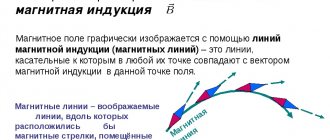
A line tangent to each point of which coincides with the direction of the magnetic induction vector is called magnetic induction line or magnetic induction line .