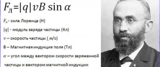
Definition
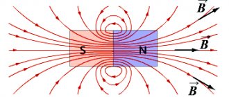
In a narrow sense, the gimlet rule is a mnemonic algorithm used to determine the spatial direction of magnetic induction, depending on the orientation of the electric current exciting the magnetic field.
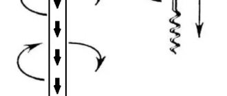
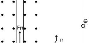
This rule can be formulated as follows: If the tip of a gimlet (corkscrew, screw) is directed along the current vector, then the orientation of the magnetic induction lines will coincide with the direction towards which the handle of the gimlet rotates in the traditional version of this tool (with a right-handed screw) [ ] (Fig. 1.)
Rice. 1. Gimlet rule for a straight conductor
Figure 1 shows a diagram for the simplest case: an electric current flows along a straight section of a conductor, away from the observer (blue arrow). The conditional corkscrew is directed with its sharp end along the line in the direction of the current. If we imagine the translational movement of a gimlet along a conductor, then the direction of the lines described by the handle of the corkscrew will coincide with the orientation of the magnetic lines of the electric field.
Examples of problems in physics and electrical engineering
As examples, problems related to the Ampere force will be considered. Examples of solutions are specific, but the solution method itself is quite simple.
Task No. 1
Initial data for execution: length of the conductor - 20 cm, current flowing in it - 300 mA, angle between the conductor and the magnetic induction vector - 45o. The magnitude of magnetic induction is 0.5 Tesla.
It is required to find the force of a uniform magnetic field acting on a conductor.
Solution: it is necessary to apply the basic formula – Fa = B x I x L x sinα. Substituting the required values, we get: Fa = 0.5 T x 0.3A x 0.2 m x (√2/2) = 0.03 N.
Problem No. 2
Initial data for the solution: The conductor is placed in a magnetic field, the induction of which is 10 Tesla. The strength of the magnetic field is perpendicular to the conductor and is 20 N. The strength of the current flowing in the conductor is 5A.
It is required to calculate the length of the conductor segment.
Solution: the formula Fa = B x I x L x sinα is taken as a basis. The length of the conductor is determined as follows: L = Fa/(B x I x sinα). Since sinα = 1, we get: L = Fa/(B x I). All that remains is to substitute the required values and get the result: L = 20N/(10T x 5A) = 0.4 m.
There are similar problems using the Lorentz force. Let us clearly consider two examples that are solved simply and clearly.
Task No. 3
Initial data for execution: in a magnetic field with an induction of 0.3 Tesla, a charge of 0.005 C moves at a speed of 200 m/s. The angle between the charge direction and the magnetic induction vector is 45º.
Determined: the magnitude of the force acting on the charge.
Solution: use the basic formula FL = |q| x V x B x sinα. Substituting the initial data, we get the following: FL = 0.005 K x 200 m/s x 0.3 T x sin 45о = (0.3 x √2)/2 = 0.21 N.
Problem No. 4
Initial data for the solution: a charged particle with a size of 0.5 mC moves in a magnetic field with an induction of 2 T. The force acting on the charge from the magnetic field is 32 N. The direction of movement of the particle and the magnetic field vector are located at an angle of 90º.
It is required to determine: the speed of movement of a charged particle.
Solution: initially take the formula FL = |q| x V x B x sinα. Since sinα = 1, it takes the following form: FL = |q| x V x B. To determine the speed you need: V = FL/(|q| x B). It remains to insert the initial data: V = 32N/(5*10-4C x 2T) = 32000 m/s.
The main rule
The example we considered is a special case of the gimlet algorithm. There are several options for wording the rule, applicable in different situations.
The general or main formulation allows this rule to be extended to all cases. This is a variant of the mnemonic rule used to determine the orientation of the resulting vector product, called the axial vector, and also to select the right basis (three-dimensional coordinate system) associated with these vectors, which allows you to determine the sign of the axial vector.
Note: right basis is a convention according to which the Cartesian coordinate system (positive basis) is selected. Sometimes it is useful to use the mirror image of the Cartesian system (left or negative basis).
The main rule allows you to determine the direction in space of axial vectors important for calculations:
- angular velocity;
- induction current parameters;
- magnetic induction.
Although the orientation of the axial vector is arbitrary, it is important for calculations: by adhering to the accepted selection algorithm, it is easier to carry out calculations without the risk of confusing the signs.
In many cases, special formulations are used that well describe special cases in a specific situation.
Video
And in conclusion, a short video lesson about the power of Ampere.
Author: Pavel Chaika, editor-in-chief of Poznavaika magazine
When writing the article, I tried to make it as interesting, useful and high-quality as possible. I would be grateful for any feedback and constructive criticism in the form of comments on the article. You can also write your wish/question/suggestion to my email [email protected] or Facebook, with respect, the author.
Author page
Right hand rule
In electrical engineering, the interpretation of the gimlet for the right hand is often used.
The actions can be formulated as follows: “If the thumb of the right hand, set aside, is placed along the conductor so that it coincides with the direction of the electric current, then the remaining fingers will indicate the direction of the magnetic lines of force formed by the electric field. (see diagram in Fig. 2).
Rice. 2. Illustration of the right hand rule
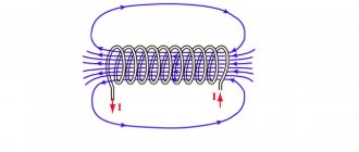
The algorithms formulated above are also applied to solenoids. But the difference is that in the case of a solenoid, the gimlet handle is rotated so that this movement coincides with the direction of the currents in the turns, and the advancement of the gimlet screw indicates the orientation of the vector of magnetic lines in the solenoid.
When using the right hand, fingers cover (conditionally) the coil so that the direction of the current in the turns coincides with the spatial arrangement of the fingers. Then the thumb will point to the orientation of the vector of electromagnetic lines inside the coil. Figure 3 shows diagrams explaining algorithms for determining the directions of vectors for solenoids.
Rice. 3. Illustration of the right hand rule for a reel
It is not difficult to guess that these rules can be applied to determine the direction of the current. For example, if you use a magnetic needle to determine the direction of magnetic induction lines, then by applying the gimlet rule (as a variant of its formulation for the right hand), it is easy to determine in which direction the current flows.
A little history
The first attempts to describe electromagnetic force were made back in the 18th century. Scientists Henry Cavendish and Tobias Mayer proposed that the force on magnetic poles and electrically charged objects obeys the inverse square law. However, the experimental proof of this fact was not complete and convincing. It was only in 1784 that Charles Augustine de Coulomb, using his torsion balance, was able to finally prove this assumption.
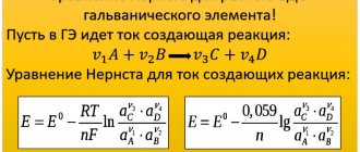
In 1820, the physicist Oersted discovered the fact that a volt current acts on the magnetic needle of a compass, and Andre-Marie Ampere in the same year was able to develop a formula for the angular dependence between two current elements. In fact, these discoveries became the foundation of the modern concept of electric and magnetic fields. The concept itself was further developed in the theories of Michael Faraday, especially in his idea of lines of force. Lord Kelvin and James Maxwell added detailed mathematical descriptions to Faraday's theories. In particular, Maxwell created the so-called “Maxwell field equation” - which is a system of differential and integral equations that describe the electromagnetic field and its relationship with electric charges and currents in vacuum and continuous media.
JJ Thompson was the first physicist to try to derive from Maxwell's field equation the electromagnetic force that acts on a moving charged object. In 1881, he published his formula F = q/2 vx B. But due to some miscalculations and an incomplete description of the bias current, it turned out to be not entirely correct.
And finally, in 1895, the Dutch scientist Hendrik Lorentz derived the correct formula, which is still used today, and also bears his name, just as the force that acts on a flying particle in a magnetic field is now called the “Lorentz force.”
Special rules
Let's consider variants of the main gimlet rule for special cases. The use of such rules often simplifies the calculation process.
For a cross product
Arrange the vectors so that their starting points coincide. For this situation, the gimlet rule sounds like this:
If one of the factor vectors is rotated in the shortest way until the directions coincide with the second vector, then the gimlet rotated in a similar way will be screwed in the direction where the vector product points.
According to the clock face
When the vectors are located by matching their starting points, you can determine the direction of the product vector using a clockwise direction. To do this, you need to mentally move one of the factor vectors along the shortest path towards another vector. Then, if you look from the direction of rotation of this vector clockwise, the axial vector will be directed deep into the dial.
Right hand rules for product of vectors
There are two versions of the rule.
First option:
If the bent fingers of the right hand are directed towards the shortest path to combine the factor vector with another factor (the vectors come from one point), then the thumb moved to the side will indicate the direction of the axial vector.
Second option:
If the right palm is positioned in such a way that the thumb coincides with the first multiplier vector, and the index finger coincides with the second, then the middle finger moved to the side will coincide with the direction of the product vector.
For bases
The rules listed above also apply to bases.
For example, the gimlet rule for the right basis can be written as follows:
When you rotate the handle of the gimlet and the vectors so that the first basis vector tends to the second along the shortest path, the corkscrew will screw towards the third basis vector.
These rules are universal. They can be rewritten for mechanics to define vectors:
- mechanical rotation (determination of angular velocity);
- moment of applied forces;
- moment of impulse.
The gimlet rules also apply to Maxwell's equations, which enhances their universality.
Practical use
The use of Ampere's force in the modern world is very wide; one can even say without exaggeration that we are literally surrounded by the power of Ampere. For example, when you are riding in a tram, trolleybus, or electric car, it is this force, the Ampere force, that sets it in motion. Elevators, electric gates, doors, any electrical appliances are similar; all this works precisely thanks to the power of Ampere.
Left hand rule
In electrical engineering, questions often arise related to the determination of the Ampere force. To solve problems of this kind, an algorithm is used called the left-hand rule (illustration in Fig. 4) - a mnemonic rule that describes a method for determining the direction of the Ampere force pushing out a point charge or a conductor through which an electric current flows.
The algorithm for using the left hand is as follows: if the left palm is perpendicularly pierced by lines of force, and the fingers are located in the direction of the current, then the forces acting on the conductor will rush in the direction where the protruding thumb is pointing.
Interpretation for a point charge
Note that the formulated rule is valid for solving problems of determining the orientation of the Lorentz force. Let's rephrase the rule: if the palm of the left hand is placed in a magnetic field in such a way that the induction lines enter perpendicularly into it, and the straightened fingers are directed in the direction of the movement of the positive charge, the direction of the Lorentz force vector will coincide with the thumb set at 90º.
A visual interpretation of the left-hand rule is presented in Figure 5. Please note that the algorithm for determining the Ampere and Lorentz forces is almost the same.
Rice. 5. Interpretation of left hand rules
Note: In the case of a negative charge, the extended fingers are directed in the direction opposite to the movement of the particle.
What is the Lorentz force - definition, when it occurs, obtaining the formula
It is known that electric current is the ordered movement of charged particles.
It has also been established that while moving in a magnetic field, each of these particles is subject to the action of a force. For a force to occur, the particle must be in motion. The Lorentz force is a force that acts on an electrically charged particle as it moves in a magnetic field. Its direction is orthogonal to the plane in which the vectors of particle velocity and magnetic field strength lie. The resultant of the Lorentz forces is the Ampere force. Knowing it, we can derive a formula for the Lorentz force.
The time required for a particle to pass through a section of conductor is
, where is the length of the segment and is the particle velocity. The total charge transferred during this time through the cross section of the conductor is
Substituting here the time value from the previous equality, we have
(2)
At the same time, where is the number of particles located in the conductor under consideration. In this case, where is the charge of one particle. Substituting the value from (2) into the formula, you can get:
Thus,
Using (1), the previous expression can be written as
After reductions and translations, a formula appears for calculating the Lorentz force
Taking into account the fact that the formula is written for the force modulus, it must be written as follows:
(3)
Since , then to calculate the modulus of the Lorentz force, it does not matter where the velocity is directed - in the direction of the current or against it - and we can say that - this is the angle formed by the vectors of the particle velocity and magnetic induction.
Writing the formula in vector form will look like this:
is a vector product, the result of which is a vector with a modulus equal to Based on formula (3), we can conclude that the Lorentz force is maximum in the case of perpendicular directions of the electric current and magnetic field, that is, when , and disappears when they are parallel (
It must be remembered that to obtain the correct quantitative answer - for example, when solving problems - you should use SI units, in which magnetic induction is measured in teslas (1 T = 1 kg s−2 A−1), force in newtons (1 N = 1 kg m/s2), current strength - in amperes, charge in coulombs (1 C = 1 A s), length - in meters, speed - in m/s.
Useful information and tips
- It is generally accepted that the direction of current points from plus to minus. In fact, in a conductor, the orderly movement of electrons is directed from the negative pole to the positive pole. Therefore, if you were faced with the task of calculating the Lorentz force for an individual electron in a conductor, you should take this circumstance into account.
- By default, we consider a screw (gimlet, corkscrew) with a right-hand thread. However, we should not forget about the existence of screws with left-hand threads.
- When using the clockwise rule, we assume that the arrows move from left to right. It is known that in the former USSR watches with a reverse movement of the clock mechanism were produced. Perhaps such models exist to this day.
Tips: if you need to determine the spatial location of the moment of force under the influence of which a certain body rotates, rotate the screw in the same direction. The conditional insertion of the screw will indicate the orientation of the force moment vector. The speed of rotation of the body does not affect the direction of the vector.
It is useful to know that when the gimlet rotates along the direction of rotation of the body, the trajectory of its screwing in will coincide with the direction of the angular velocity.
Magnetic field in a solenoid
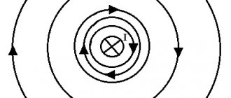
The laws of the right and left hands in physics, discussed earlier, are one hundred percent valid only for straight conductors. However, quite often wires are used in the form of coils or solenoids, where all processes occur differently.
It is known that under the influence of an electric current passing inside a wire, a circular magnetic field is formed. In coil solenoids, the wire is coiled into rings and wrapped repeatedly around a core. Here, the Guravchik rule in its pure form no longer functions, since a significant increase in magnetic fields occurs. But, its conditional lines are directed in the same way as those of permanent magnets, so in this case it is possible to apply the right-hand rule.
First, the solenoid is wrapped so that the largest finger points in the direction of the magnetic north pole. It also displays the direction of the magnetic induction vector. The remaining four fingers are located in the direction of current flow.
It is possible to partially apply the corkscrew rule. It should be installed and twisted in the direction of the current, then the tip will move in the direction of electromagnetic induction. This setting applies not only to the entire coil, but also to a single turn.