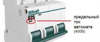
What is an independent release
An independent release is a device that remotely deactivates protective equipment. Most often it is used in conjunction with circuit breakers with 1-4 poles. The release system is connected to the input mechanism. When an emergency is activated, it cuts off the electrical current completely.
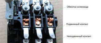
What is a circuit breaker
The design of the unit is made in the form of an electromagnet. When it receives a pulse, the profile lever begins to act on the electrical mechanism, deactivating the protective device.
The electromagnetic coils with which the device is equipped pass alternating or direct current. The optimal voltage level for them is 12-60 V and 110-415 V. The method of coupling with the machine is selected depending on the type of coil.
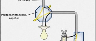
Connection diagram for independent release device
Note! Fixation usually occurs on the right or left side.
Checking the functionality of releases
Quite often, amateur electricians are interested in whether it is possible to independently check the serviceability of circuit breaker releases. It should be said that such testing cannot be carried out on your own, and if it is carried out by a novice installer, then the work should be supervised by an experienced specialist. Here are step-by-step instructions for performing this procedure:
- First of all, the surface of the box should be visually inspected to ensure the integrity of the body part.
- Then you need to click the switch lever several times. It should be easy to install in either the on or off position.
- After this, the device is loaded. This is the name for checking the quality of equipment operation under adverse conditions. This stage requires the presence of specialized equipment, and a qualified electrician must be present when performing it. During testing, the time that passes from the moment the current begins to increase until the release is turned off is recorded.
- Finally, a similar test is performed on the device from which the housing has been removed.
- During testing for the operation of a thermal release, the time required to turn off the device under the influence of an electric current of increased strength is recorded.
Checking the serviceability of protective devices in accordance with the requirements of the PUE is carried out only in special clothing. As mentioned above, this procedure should be supervised by an experienced specialist.
The video shows the process of installing an independent release in a circuit breaker:
Technical characteristics of the release
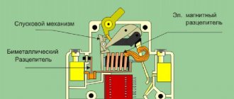
There are two types of tripping devices inside the machine. Each of them operates in its own current range. If both devices start working at the same time, this leads to the machine turning off when an overcurrent passes through it.
The thermal release mechanism operates by heating the bimetallic strip. It is calibrated and, at a certain current, heats up to certain levels. This causes a critical bend to occur and the machine to deactivate.
The second unit, electromagnetic, operates at a higher speed than thermal. It operates on the basis of an electromagnet that turns off the load when a short circuit occurs. The current of the electromagnetic switch is 3 times higher than the voltage of the thermal device. It can also be 20 times higher.
The automatic release is equipped with a diode rectifier. System dinistors are used with different conductivities. Devices for phase switches require the use of a transceiver. The relay is installed at the bottom of the system. The solenoid coil is usually rated for 12-60 V AC.
You may be interested in this Digital electronic electricity meter
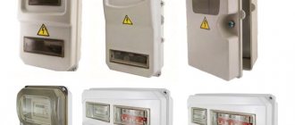
Compact circuit breaker
Note! In some units, the voltage is kept at 110-415 V.
Thermal release of circuit breaker
The main element of this device is a bimetallic plate. In its manufacture, two metals with different coefficients of thermal expansion are used.
Being pressed together, they expand to varying degrees when heated, which leads to curvature of the plate. If the current is not normalized for a long time, then upon reaching a certain temperature the plate touches the AB contacts, interrupting the circuit and de-energizing the wiring.
The main reason for excessive heating of the bimetallic plate, due to which the thermal release is triggered, is too high a load on a certain section of the line protected by the circuit breaker.
For example, the cross-section of the AB output cable going into the room is 1 square meter. mm. It can be calculated that it is capable of withstanding the connection of devices with a total power of up to 3.5 kW, while the strength of the current passing in the line should not exceed 16A. Thus, you can easily connect a TV and several lighting fixtures to this group.
If the owner of the house decides to plug in an additional washing machine, electric fireplace and vacuum cleaner into the sockets of this room, then the total power will become much higher than what the cable can withstand. As a result, the strength of the current passing through the line will increase, and the conductor will begin to heat up.
Overheating the cable can cause the insulating layer to melt and catch fire.
To prevent this from happening, a thermal release is activated. Its bimetallic plate heats up along with the metal of the wire, and after some time, bending, turns off the power to the group. When it has cooled down, the protective device can be turned on again manually, after first unplugging the power cords of the devices that caused the overload. If this is not done, after a while the machine will turn off again.
An example of using a release in fire protection in the video:
It is important that the AB rating matches the cable cross-section. If it is less than required, then operation will occur even under normal load, and if it is more, then the thermal release will not respond to a dangerous excess of current, and as a result the wiring will burn out.
In order to protect electric motors from prolonged overloads and phase failure, thermal release relays can also be installed on these units. They are several bimetallic plates, each of which is responsible for a separate phase of the power unit.
Purpose of independent release
An independent release is an additional equipment for circuit breakers. It is used to remotely open load switches. Trip devices are primarily used to design ventilation systems.
Automatic system diagram
If we focus on regulations, then ventilation in the event of a fire must be capable of deactivation. To do this, an independent release is most often connected to the input device. It can switch off single-phase and three-phase systems.
Note! For the system to start working, it is necessary to apply an impulse to the coil of the protective unit. To restore the device to its original state, you will need to activate the return button.
24 A devices
24 A devices consist of diode rectifiers. They are installed with different conductivities. As a rule, the protection system is used in the IP21 series. However, in this case, much depends on the manufacturer. Modulators are used only of the orthogonal type. Models based on semiconductor thyristors are suitable for pulse switches.
Stabilizers in devices are used with low sensitivity. The output voltage of this type of release does not exceed 20 V. On average, the current conductivity is 3 μm. Insulators are used to secure the device to the panel. If we consider modifications without transceivers, then they use a capacitor unit. Many modifications are suitable for low voltage circuit breakers.
Principle of operation
The essence of the operation of an independent release device is based on changing the arrangement of contacts. This happens due to the arrival of a short pulse from the diode rectifier. In this case, a transistor acts as a conductor. The switch frequency is adjusted using a modulator. To combat electromagnetic interference, a kenotron is used.
Automatic release PH 47
Externally, the device is a housing made of wear-resistant plastic. The activation button is located on the front of the system. There is a locking latch on the back of the unit and screw terminals at the bottom.
In normal operation, the device passes a current that is equal to the rated value (it can also be less). The top terminal carries the supply voltage from the external network. After this, the current is supplied to the thermal switch, then to the electromagnetic switch. If an emergency occurs, the release disconnects the protected circuit and turns off the machine.
Important! Most often, the system is triggered by a short circuit.
20 A models
20 A releases are often used for phase switches. The threshold voltage parameter for the models is around 220 V. Some modifications are made with stabilizers. It is also important to note that there are releases on the market with an IP20 protection system. The transistors in them are of the broadband type. All this suggests that they can withstand large overloads in the circuit.
Many models are connected to the panel via kenotrons. They are most often produced as a two-pin type. The current conductivity of many models does not exceed 5 microns. It is also important to note that models for ventilation systems are produced with capacitor modulators. In some cases they are mounted with expanders. They are excellent for remote control of switches.
Independent release design
An independent switch is a specialized device for remotely deactivating a machine. The design of the system resembles a magnet. During the period when it is influenced by a short-term impulse, the release mechanism, using the equipped lever, exerts pressure, due to which the protective device is switched off.
Circuit breaker pin
Each design has an electromagnetic coil with different power ratings. The release mechanism passes direct and alternating currents. The voltage level varies from 110 to 415 V or from 12 to 60 V. The degree of indicators usually depends on the model of the unit.
You might be interested in: Alternating current generator design
The difference between composite releases is the current protection. The electromagnetic device presents it without a time delay, that is, without a current cutoff.
For your information! The thermal release device implements the integral dependence of the response time of the protective system on the current value. It ensures that automatic equipment is turned off in case of overload, when the consumed current becomes 20% more than the rated current.
Installation
Many home-grown electricians believe that installing a machine is not difficult. This is fair, but certain rules must be followed. Circuit breaker releases, as well as plug fuses, must be connected to the network so that when the plug of the circuit breaker is turned out, its screw sleeve is without voltage. The connection of the supply conductor for one-way power supply to the machine must be made to the fixed contacts.
Installation of an electric single-phase two-pole circuit breaker in an apartment consists of several stages:
- securing the switched-off device to the electrical panel;
- connecting wires without voltage to the meter;
- connecting voltage wires to the machine from above;
- turning on the machine.
Fastening
We install a DIN rail in the electrical panel. We cut it to the required size and fasten it with self-tapping screws to the electrical panel. We snap the automatic circuit breaker onto the DIN rail using a special lock, which is located on the back of the machine. Make sure that the device is in shutdown mode.
Connection to the electricity meter
We take a piece of wire, the length of which corresponds to the distance from the meter to the machine. We connect one end to the electric meter, the other to the terminals of the release, observing the polarity. We connect the supply phase to the first contact, and the neutral supply wire to the third. Wire cross-section – 2.5 mm.
Connecting voltage wires
From the central electrical distribution panel, the supply wires are connected to the apartment panel. We connect them to the terminals of the machine, which must be in the “off” position, observing the polarity. The wire cross-section is calculated depending on the energy consumed.
Turning on the machine
Only after all the wires have been installed correctly can the automatic current release be put into operation.
It happens that the constant shutdown of the machine becomes a big problem. Do not try to solve this problem by installing a trip unit with a higher current rating. Such devices are installed taking into account the cross-section of the wires in the house, and, perhaps, a large current in the network is unacceptable. The problem can only be solved by inspecting the electrical supply system of the apartment by professional electricians.
Finally found a minute to write a new article. An independent release is an additional device to circuit breakers. Now we will talk about the use of an independent release in our projects and how to correctly connect an independent release.
An independent release allows you to remotely open a circuit breaker or load switch. Most often, independent releases are used when designing ventilation. According to regulatory documents, ventilation must be turned off in case of fire, therefore, in addition to the input device of the ventilation panel, an independent release is installed. Switchboards up to 100A are equipped with modular circuit breakers. A load switch can be installed at the input to the switchboard. It is the input device that we turn off using an independent release. With a current of more than 100A, a BA88 series circuit breaker can be installed at the input to the switchboard. An independent release can also be installed on this device. In my projects it has not yet been necessary to remotely turn off the BA88 =)
Now let's move on to the connection diagram for the independent release.
The independent release can disconnect both single-phase and three-phase devices. To activate the independent release, it is enough to apply a voltage pulse to the release coil. To restore the machine to its original state, you must manually press the “return” button. This allows you to signal why the circuit breaker tripped: either from an overload (short circuit) or from a remote shutdown.
The independent release control circuit is presented below.
It is very important here that the phase conductor is connected from one of the phases from under the lower terminals of the circuit breaker. If connected incorrectly, the independent release will be damaged. After the machine is turned off, the voltage from the release coil disappears.
The control signal for triggering the independent release can be a closing contact from a fire alarm device or a regular button with a closing contact.
Sometimes a situation may arise when you need to turn off several independent releases at once with one signal. For example, you have 2-3 fans, which make no sense to separate them into a separate cabinet. Therefore, we install our own independent release for each group. This topic was raised on the forum...
The control diagram for several independent releases from one signal is presented below.
The main thing here is that the same phase is used.
It is worth noting that an independent release is not a cheap pleasure. Its size is the same as that of a single-pole circuit breaker (1 module), but costs an order of magnitude more.
“, here I want to tell you how to correctly connect the independent release S2C-A1 from ABB. Of course, it is not used at home, since it is not necessary, but you can use it at work, in the office, etc. It is used to de-energize the panel of air conditioners and other electrical equipment when a “Fire” signal appears from the fire alarm. Therefore, this article may be useful to you. I was prompted to write it by the incorrect connection of this release by the installers in our panel. Also, after looking on the Internet, I realized that this problem occurs quite often. They often write on forums that the release does not turn off the input circuit breaker because it does not have enough current. This is fundamentally wrong. This release may not turn off the input circuit breaker only due to the poor competence of the installers in working with these devices.
A few words about the device itself. The independent release S2C-A1 is designed for remote shutdown of protective devices. It connects to ABB S200 series circuit breakers and DS200 series automatic circuit breakers. Usually it is connected to input circuit breakers to enable remote shutdown of the entire power supply panel.
There are two types of release depending on the voltage level of its coil. These are S2C-A1 and S2C-A2. Their abbreviations differ only in the last digits. To operate the S2C-A1, a DC or AC voltage of 12 to 60 V is required. This voltage is usually taken from fire alarm devices. To operate S2C-A2, you need a constant or alternating voltage from 110 to 415 V. As you can see, the only difference is in the voltage level. These types of releases are connected to circuit breakers only on the right side. If suddenly for some reason you need to connect the independent release to the machine on the left side, then you need to order S2C-A1L or S2C-A2L. This is indicated by the last letter “L” in the designation.
The connection diagram for the independent release is very simple. It has only two contacts to which the wires are connected. But installers often miss one little thing, due to which the circuit does not work and the panels are not de-energized.
I'll tell you about our case. For us, it all started with the fact that when a fire signal was sent to S2C-A1, it did not turn off the input circuit breaker, but something inside the release clicked. One got the feeling that he simply did not have enough strength to move the handle of the machine gun.
Below is a photo of the input circuit breaker of our air conditioner power supply panel. This is a 3-phase circuit breaker with an independent release S2C-A1 connected to the right side.
It was decided to dismantle this entire facility to find an answer to the question: what could be the matter?
S2C-A1 is disconnected from the machine with little effort. To do this you need to pull them in different directions. To help, insert a slotted screwdriver between them.
It turned out that this independent release acts on the machine only through a thin metal pin that connects their control handles. This is not enough to remotely turn off the machine. Have you tried turning off a 3-pole circuit breaker by hand? This requires strength. Therefore, the machine must be influenced by something else that is not here.
It turns out everything is simple. As people say: “It wasn’t the reel.” There was a small, harmless plastic fork missing. Against the background of these powerful devices, she looks somehow helpless.
Its length is about 16 mm.
This fork must be inserted into both devices into special grooves. On the machine, this groove is initially sealed with a round plug. It can be easily removed with a screwdriver.
I cocked the machine and lightly pressed the mechanism with a screwdriver through the open hole and the machine immediately turned off. Hooray! All that remains is to find such a fork.
As it turned out, it is not sold separately and you only need to buy a new release S2C-A1, which costs about 1250 rubles. It was useless to look for the old one, since it had been in the trash for several months. Where to go - bought it.
The independent release S2C-A1 from ABB is sold in plastic packaging. The fork we need is in the same package, but in a special compartment. Be careful!
You can clearly see it in the bottom photo.
When the installers open the package, the fork flies away and no one has any problems. Something like this! These are our installers!
I don’t understand why during the development of this device it was impossible to provide for its initial attachment to the release. That is, make it so that it is one with this fork and it does not disconnect from it. It already has three pins sticking out. They would have done the fourth one and there would have been no problems. Or at least write a warning on the packaging in large letters: “Attention! There's a little thing inside! Don't lose it!"
Everything is ready for assembly...
This fork has a triple fork on one and a double fork on the other. So, the triple plug needs to be inserted into the machine itself. She sits there well. And the double plug must go into the S2C-A1 release.
It looks something like this...
Snap it on and you're done!
Repeated testing of the independent release with the plug installed showed that the S2C-A1 very easily and quickly trips a powerful three-phase circuit breaker. As you can see, more current is not needed here, as is advised on some forums.
Thank you for your attention!
Let's smile:
Strange people - electricians! They are standing on the ground and looking for land!
Each device that functions as a protective mechanism for electrical networks in the home contains an independent trip for the circuit breaker. Such a device implies a mechanical connection with the switch and is considered built into the machine.
The purpose of this device in an automatic device is to help disconnect the electrical network in the event of an approaching negative factor, such as a short circuit or current leakage from the device itself or household units.
Attention!
Use the equipment strictly within the specified temperature conditions. Deviation from the norm is not recommended
.
In fact, scientists have recorded a large number of cases why the independent release tripped, but the most common and most often encountered in front of you:
- reduction of voltage in the electrical circuit;
- increase in voltage, change in current state;
- changing specified characteristics;
- incomprehensible failure and dysfunction of the machines.
Shunt release
For so many reasons, modern devices are usually equipped with several mechanisms to favorably decouple the network. They are made mainly from electromagnetic and mechanical, sometimes electronic particles. The circuit breaker release will allow you to leave all existing equipment in the household intact. It is customary to divide these built-in devices into two types.
Connection diagrams for independent release (PH 47)
If we take into account the ventilation design, then the release must be connected through dinistors. The connection of the output wires in this case occurs through insulators. The unit is connected to the circuit breaker through a negative resistance of 25 ohms.
Stages of connecting an independent release to a circuit breaker:
- To ensure connection with the relay, craftsmen use an expander.
- When connecting the release device, you will also need to check the threshold resistance of the system. It should not be higher than 30 Ohms.
- The switch must be secured in the power panel.
Note! To check the voltage, the technician should use a tester.
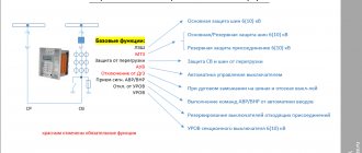
Protection system for electrical networks
An independent release is a switching unit that turns on currents, as well as conducts and turns them off under normal conditions in the circuit. It is used to protect electrical circuits from overloads or short circuits. The characteristic features of the trip unit are repeated use and stable operation in critical cases.
Types of switches
All machines are divided according to the type of release. They are divided into 6 types:
- thermal;
- electronic;
- electromagnetic;
- independent;
- combined;
- semiconductor.
They very quickly recognize emergency situations, such as:
- the occurrence of overcurrents - an increase in the current strength in the electrical network that exceeds the rated current of the circuit breaker;
- voltage overload – short circuit in the circuit;
- voltage fluctuations.
At these moments, the contacts in the automatic releases open, which prevents serious consequences in the form of damage to wiring and electrical equipment, which very often leads to fires.
Thermal switch
It consists of a bimetallic plate, one of the ends of which is located next to the release device of the automatic release. The plate is heated by the current passing through it, hence the name. When the current begins to increase, it bends and touches the trigger bar, which opens the contacts in the “machine”.
The mechanism operates even with slight excesses of the rated current and an increased response time. If the load increase is short-term, the switch does not trip, so it is convenient to install it in networks with frequent but short-term overloads.
Advantages of a thermal release:
- absence of contacting and rubbing surfaces;
- vibration stability;
- budget price;
- simple design.
The disadvantages include the fact that its operation largely depends on the temperature regime. It is better to place such machines away from heat sources, otherwise there is a risk of numerous false alarms.
Electronic switch
Its components include:
- measuring devices (current sensors);
- Control block;
- electromagnetic coil (transformer).
At each pole of the electronic circuit breaker there is a transformer that measures the current passing through it. The electronic module that controls the trip processes this information, comparing the obtained result with the specified one. In the event that the resulting indicator is greater than the programmed one, the “machine” will open.
There are three trigger zones:
- Long delay. Here, the electronic release serves as a thermal release, protecting the circuits from overloads.
- Short delay. Provides protection against minor short circuits that usually occur at the end of the protected circuit.
- The working area “instantly” provides protection against high-intensity short circuits.
Pros - a large selection of settings, maximum accuracy of the device to a given plan, the presence of indicators. Cons: sensitivity to electromagnetic fields, high price.
Electromagnetic
This is a solenoid (a coil of wound wire), inside of which there is a core with a spring that acts on the release mechanism. This is an instant action device. As the supercurrent flows through the winding, a magnetic field is generated. It moves the core and, exceeding the force of the spring, acts on the mechanism, turning off the “automatic machine”.
Pros: resistance to vibration and shock, simple design. Cons – forms a magnetic field, triggers instantly.
This is an additional device to automatic releases. With its help, you can turn off both single-phase and three-phase circuit breakers located at a certain distance. To activate the independent release, voltage must be applied to the coil. To return the machine to its original position, you must manually press the “return” button.
Important! The phase conductor must be connected from one phase from under the lower terminals of the switch. If it is connected incorrectly, the independent switch will fail.
Basically, independent automatic machines are used in automation panels in highly ramified power supply devices of many large facilities, where control is transferred to the operator’s console.
Combination switch
It has both thermal and electromagnetic elements and protects the generator from overloads and short circuits. To operate the combined automatic release, the current of the thermal circuit breaker is indicated and selected: the electromagnet is designed for 7–10 times the current, which corresponds to the operation of heating networks.
The electromagnetic elements in the combination switch provide instantaneous protection against short circuits, and the thermal elements protect against overloads with a time delay. The combined machine is switched off when any of the elements is triggered. During short-term overcurrents, none of the types of protection are triggered.
Semiconductor switch
It consists of alternating current transformers, magnetic amplifiers for direct current, a control unit and an electromagnet that functions as an independent automatic release. The control unit helps set the selected contact release program.
Its settings include:
- regulation of the rated current in the device;
- setting the time;
- triggered when a short circuit occurs;
- protective switches against overcurrent and single-phase short circuit.
Pros - a large selection of regulation for different power supply schemes, ensuring selectivity to series-connected circuit breakers with fewer amperes.
Cons: high cost, fragile control components.
Features of operation of network protection circuit breakers
Whatever class the circuit breaker belongs to, its main task is always the same - to quickly detect the occurrence of excessive current and de-energize the network before the cable and devices connected to the line are damaged.
Currents that may pose a danger to the network are divided into two types:
- Overload currents. Their appearance most often occurs due to the inclusion of devices in the network, the total power of which exceeds what the line can withstand. Another cause of overload is a malfunction of one or more devices.
- Overcurrents caused by short circuit. A short circuit occurs when the phase and neutral conductors are connected to each other. In normal condition they are connected to the load separately.
The design and principle of operation of the circuit breaker is on video:
https://youtube.com/watch?v=9bTw3wtgOWY
Overload currents
Their value most often slightly exceeds the rating of the machine, so the passage of such an electric current through the circuit, if it does not drag on for too long, does not cause damage to the line. In this case, instantaneous de-energization is not required in this case; moreover, the electron flow often quickly returns to normal. Each AV is designed for a certain excess of electric current at which it is triggered.
A thermal release, the basis of which is a bimetallic plate, is responsible for turning off the power under the influence of a powerful load.
This element heats up under the influence of a powerful current, becomes plastic, bends and triggers the machine.
Short circuit currents
The flow of electrons caused by a short circuit significantly exceeds the rating of the protective device, causing the latter to immediately trip, cutting off the power. An electromagnetic release, which is a solenoid with a core, is responsible for detecting a short circuit and immediate response of the device. The latter, under the influence of overcurrent, instantly affects the circuit breaker, causing it to trip. This process takes a split second.
However, there is one caveat. Sometimes the overload current can also be very large, but not caused by a short circuit. How is the device supposed to determine the difference between them?
In the video about the selectivity of circuit breakers:
Here we smoothly move on to the main issue that our material is devoted to. There are, as we have already said, several classes of AB, differing in time-current characteristics. The most common of them, which are used in household electrical networks, are devices of classes B, C and D. Circuit breakers belonging to category A are much less common. They are the most sensitive and are used to protect high-precision devices.
These devices differ from each other in terms of instantaneous tripping current. Its value is determined by the multiple of the current passing through the circuit to the rating of the machine.