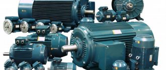
Electric motors are quite complex mechanisms that are capable of developing high power, due to which they ensure the operation of many devices. The scope of their application is extensive - they can be found in a vacuum cleaner, meat grinder, and washing machine. But everything is not limited to domestic conditions, and these mechanisms can be part of industrial equipment, where they are capable of much greater functionality. At the same time, sooner or later, malfunctions of electric motors occur.
If in everyday life a breakdown is limited only to discomfort, then on an industrial scale this leads to forced interruptions in the operation of electrical equipment. And such delays in production are extremely undesirable, so it is necessary to promptly identify the cause of the malfunction and eliminate it as soon as possible.
Electric motor design
There is no point in going into details, so we will limit ourselves to a short course. From a design point of view, any electric motor consists of two main parts:
- Stator is a stationary part that is attached to the mechanism body.
- The rotor is the rotating part due to which the devices operate.
In this case, the rotor is located in the stator cavity and does not mechanically contact it in any way, but at the same time it can come into contact through bearings. When analyzing a fan motor or any other device for faults, the first thing to check is the ability of the rotor to rotate. To do this, the first step is to completely remove the voltage from the power circuit and only then can you manually rotate the rotor.
For an electric powertrain to operate, two important conditions are necessary. Firstly, its winding (multiphase electric motors have several of them) must be supplied with a rated voltage. Secondly, both the electrical and magnetic circuits must be in full working order.
Dismantling an old electric motor
It seems there is nothing easier than disassembling the electric motor, unscrewing 8 bolts, removing the covers, and here it stands disassembled. I completely agree with this, but only when the electric motor undergoes regular scheduled inspection is it not difficult to disassemble it.
Now let's imagine a situation where the electric motor has not been disassembled for eight years and has been operated, to put it mildly, in not very favorable conditions. I once had to disassemble an electric motor that was inspected under Gorbachev, and there was little pleasure in it.
The first stage is removing the pulley or coupling half. They are usually removed by lightly tapping a piece of wood with a hammer. But in our case, everything is different; the coupling half or pulley is tightly stuck to the shaft.
We bring to your attention a review of the well-proven Wilson Diesel generator, which is ideally suited as an emergency and main source of electric current.
What kind of lighting do you prefer?
Built-in Chandelier
Electric motors operating on direct current
These mechanisms have a fairly wide range of uses:
- fans of computer devices;
- vehicle starters;
- powerful diesel stations;
- grain harvesters, etc.
The magnetic field of the stator of these mechanisms is created by two electromagnets, which are assembled on special cores (magnetic cores). Around them there are coils with windings.
The magnetic field of the moving element is formed by the current that passes through the brushes of the commutator unit along the winding laid in the grooves of the armature. We will definitely touch on the topic of electric motor rotor malfunction, but a little later.
AC motors
These mechanisms can be either asynchronous or synchronous. Some similarities can be identified between induction models and DC motors. However, there are design differences. The rotor of asynchronous power electrical installations is made in the form of a short-circuited winding (there is no direct current supply to it from the electrical installation). Popularly, this design received a rather sonorous name - “squirrel wheel”. In addition, in such engines there is a different principle of arrangement of stator turns.
In synchronous power units, the windings of the coils on the stator are located at the same offset angle to each other. Due to this, electromagnetic field lines are formed, which rotate at a certain speed.
The rotor electromagnet is located inside this field. Under the influence of the applied magnetic field, it also begins to move in accordance with the frequency synchronous with the rotation speed of the applied force.
Asynchronous motor with hollow perforated rotor
Today, engines with hollow units are very widespread in systems with trajectory control, as well as in servo systems that transmit angles. Sometimes they can be found in turn speed indicators and inertial navigation systems.
In the most common designs of an engine of this type, there are stators with control and excitation winding, laminated magnetic circuits and solid hollow parts. But this technical solution has one drawback - they negatively affect the energy characteristics of the units. This is due to eddy currents, which are closed even in the active areas of the units, and not just in the protruding frontal parts.
There is an induction motor with 2 packages (excellent design) that contain winding and hollow units. They have windows on the cylindrical part, located near the active long stator, forming a toothed zone. Despite all this, the tooth zone of the stators is located moving ¼ of the tooth divisions.
This design of the electric machine has disadvantages - low efficiency. The presence of grooves located along the active length will determine high values of the active components of the resistance of hollow shafts. The resulting effect is dominant when compared to the lower resistance of transverse edge effects in the material.
What is the concept of rotating magnetic fields?
To understand rotating magnetic fields, it is advisable to understand simplified three-phase windings with 3 turns. Current flowing through conductors creates magnetic fields around them. Each of the components of alternating current will change over time. As a result, the generated magnetic field will change. Also, the resulting magnetic fields of the 3-phase windings will take different types of orientation. The amplitude is the same.
How does a magnetic rotating field act on closed turns?
When a closed conductor is placed inside a magnetic field that rotates, then according to the law of electromagnetic induction, the magnetic fields that change will lead to the appearance of an electromotive force in the conductor. And then the EMF will cause a current to arise in the conductor. It turns out that there is a closed conductor with current in magnetic fields. If you believe Ampere's law, then the force will begin to act, and as a result the circuit will be transferred to the rotational mode.
Regarding squirrel cage rotors of asynchronous motors
Such engines are also capable of working on this principle. Instead of frames with current, inside the asynchronous electric motor there is a part of a short-circuited plan - their design features resemble squirrel wheels. Therefore, squirrel-cage rotors consist of a rod that is closed at the end by a ring. Three-phase alternating current, when passing through the stator winding, creates a magnetic field with rotation. It turns out that a current is induced in the rod, and as a result the unit begins to rotate.
How to connect asynchronous motors:
- The three-phase alternating current (AC) electrical network has become more widespread among all electrical systems that carry power. The main advantage of a 3-phase system, when compared with a single-phase system, is its economical performance. In it, energy will be supplied through 3 wires, and the current flowing in different wires will be shifted relative to each other in phase by 120 degrees. And do not forget that sinusoidal EMF at different phases has the same amplitude and frequency.
- Phase voltages - we are talking about the potential difference between the end and the beginning of one of the phases. Phase voltage is the difference between line wires and neutral wires.
- Triangles with stars - the 3-phase winding of the stators of the electric motor is connected according to a triangle or star circuit. It all depends on the supply voltage of the networks. The ends of the 3-phase windings can be connected inside the electric motors or brought out, also brought out into distribution boxes.
It is worth noting that regardless of the power that is used to connect triangles with stars, they must be calculated using one of the formulas for connecting the same electric motor, but in different ways. When they are connected in the same electrical network, this leads to the consumption of different powers. If you connect the electric motor incorrectly, the stator windings may melt.
Rotor rotation estimation
Troubleshooting an AC motor involves various manipulations of the rotor. Often the ability to assess the degree of rotation of this moving element is complicated by the connected drive. For example, the power unit of a vacuum cleaner can be unscrewed by hand without any problems. And in order to rotate the working shaft of the hammer drill, you need to make some effort. But if the shaft is connected to a worm gear, then in this case, due to the peculiarities of this mechanism, it will not be possible to turn it at all.
It is for this reason that rotor rotation is checked only when the drive is turned off. But what can make it difficult to rotate? There are several reasons for this:
- The sliding contact pads are worn out.
- The bearings are missing grease or the wrong compound has been used. In other words, ordinary grease, which is usually used to fill ball bearings, thickens at strong negative temperatures. This may cause the electrical mechanism to start poorly.
- The presence of dirt or foreign objects between the stator and rotor.
Typically, the cause of a motor bearing failure is not difficult to determine. The broken part begins to make noise, which is additionally accompanied by play. To identify this, it is enough to shake the rotor in a vertical or horizontal plane. You can also try moving the rotor in and out along its axis. It is worth considering that a slight backlash is the norm for most power unit models.
Insufficient motor speed
As a rule, identifying mechanical faults in bearings does not answer the question why the electric motor does not gain speed . The cause may be a fault in the driven load. But, if the bearings of an engine free from load are so dirty and worn out that the shaft cannot spin, then this phenomenon will not be observed for very long - due to friction and high heat generation, the steel of the ball bearings will heat up, and they will literally be ground, which will ultimately lead to rotor jamming.
Some of the ball bearing rollers are literally “smeared” across the cage ring
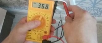
Therefore, the cause of insufficient speed should be sought in internal or external electrical problems. The first step is to make sure the quality of the electricity supplied to the motor terminals - the voltage must correspond to the nominal value.
Phase-to-phase voltage is within normal limits
You should also check the contact pads of the starter contactors - at high currents they can burn out, which will cause a voltage drop across them. Faulty, worn contactors may experience contact bounce, resulting in interruption of current.
The oscilloscope screen displays contact bounce that led to a current interruption
A popular way to check the performance of the starter is to connect to it another serviceable electric motor of the same type, the same or slightly less power.
Major faults in the internal electrical system affecting engine speed.
Having ruled out external electrical faults, it is necessary to check the motor windings for breakdown and breakage. The multimeter is switched to megger mode and the insulation resistance of the windings is measured by applying probes alternately to each terminal and the housing. If zero is displayed on the display, then there is an obvious breakdown - somewhere the insulation has frayed and the wire is in direct contact with the housing.
Illustration of the process of measuring the resistance of electric motor windings
With these measurements, the display may show resistance within a few megaohms - in this case, you need to look at the documentation for the motor and check the insulation resistance graph.
Table for assessing the quality of insulation resistance of electric motors
It is quite possible that high humidity and the presence of small metal shavings in the engine will worsen the dielectric properties of insulating materials. These leakage currents flowing through defective insulation negatively affect both the efficiency of the electric motor and the electrical safety of its operation.
Detection of faults in electric motor windings
A break in one of the windings can cause the engine to not start at all and will hum strongly until the protection is triggered or the remaining coils burn out. To detect a break in the windings of a three-phase asynchronous motor, it is necessary to disconnect the jumpers that form the star or delta connection and check each winding individually.
Illustration of the process of testing electric motor windings
This method will be the most reliable and will not allow a novice master to get confused. The test is carried out in ohmmeter mode. Depending on the quality of the device and the power of the engine, the ohmmeter readings will be close to zero, amounting to several ohms.
It is important here that the resistance of the windings is the same. The condition of equal winding resistance is also true for DC motors. These electric motors have two or more stator windings and multiple rotor windings connected to commutator contact plates.
Continuity check of the rotor windings of a commutator electric motor
If one of the windings has less resistance than the others, this indicates that a short circuit has occurred between some turns of the coil, which is called an interturn short circuit.
Detection of inter-turn short circuit in motor windings
It is precisely this inter-turn short circuit that very often causes the engine to insufficiently rev up. Conventional multimeters are not accurate enough to measure tenths of an ohm. Therefore, additional resistance of the rheostat is used, forming a voltage divider together with the winding under test, a stabilized power supply, a voltmeter and an ammeter. The voltage drop on each winding is measured - if they are in good condition, the voltmeter readings will be the same. A lower voltage will indicate the presence of an interturn short circuit even without calculating the winding resistances, which can be done using the formula shown in the figure.
Calculation of winding resistance via voltage drop
Under the condition of phase equality, an interturn short circuit in the windings of a running three-phase asynchronous motor can be detected by measuring the currents in each phase. An increased current in one phase when connecting the motor windings with a star, or a higher current in two phases when connecting the windings in a triangle, will indicate an interturn short circuit.
Sometimes you can find the place of an interturn short circuit in an asynchronous motor using the traditional method - remove the rotor and apply a reduced three-phase voltage to the windings - no more than 40 V (to ensure electrical safety and so that the coils do not burn out).
A metal ball is placed in the cylinder of a horizontally standing stator, which will begin to roll along the inner surface of the stator, following the rotating magnetic field.
Turn-to-turn fault detection using a steel ball
If the ball suddenly becomes magnetized to one place, then its location will indicate an interturn short circuit.
Basic malfunctions of commutator electric motors
DC and AC commutator electric motors often have a malfunction associated with wear of the contact plates and commutator brushes. With severe wear and contamination of the contacting surfaces, the resistance of the commutator contacts will increase, which will lead to a decrease in torque and engine efficiency.
Cleaning the commutator plates with sandpaper
Ultimately, such wear leads to periodic loss of contact between the brush and the plate, and intermittent operation of the electric motor is observed during rotation.
Damaged rotor commutator contact plates
When starting, such an electric motor may not start at all. If, when voltage is applied, a DC or AC commutator motor sometimes starts after pushing its shaft, then it is necessary to replace the brushes and clean the commutator plates. Sometimes increased sparking is observed at one of the brushes - this indicates a displacement of the brush relative to the central line perpendicular to the axis of the shaft, passing through the center. Centering the brushes will help eliminate this defect.
Correctly align the commutator brushes
You can familiarize yourself with the process of checking brushed motors by watching the video below
Malfunctions in the magnetic circuit, worsening the characteristics of the electric motor
If everything is in order with the mechanical and electrical parts of the AC motor, but it is felt that it is not operating at maximum power and there is increased heat generation, then a short circuit between the magnetic circuit plates is possible.
Alternating current in the magnetic circuit causes eddy currents, which worsen the characteristics of the electric motor, so the stator and rotor are made of laminated plates of special electrical steel. These plates are covered with insulation in the form of an oxide layer, spraying or varnish.
If, due to mechanical damage or rust, the insulation between the laminated plates is broken, a short circuit occurs between them.
Presence of rust on the surface of the rotor magnetic circuit
It is almost impossible to detect a short circuit in the magnetic circuit plates using home measuring instruments, so a full diagnosis of engine faults is needed in a specialized workshop.
Sometimes a short circuit in the magnetic circuit can be detected by careful inspection of the surface, or by noticing local increased heating of the magnetic circuit. But without completely disassembling the entire engine, including the magnetic circuit, this malfunction cannot be eliminated.
The tables below contain the most common malfunctions and breakdowns of electric motors, as well as methods for eliminating them.
Engine fault table, part one
Electric motor fault table, part two
Checking the brushes
The commutator plates are essentially the contact connection of part of the continuous armature winding. Through this connection, electric current is supplied to the brushes. While the power unit is in good condition, a transient electrical resistance is formed in this unit. Fortunately, it is not capable of having any significant effect on the operation of the mechanism.
How to determine if an electric motor is faulty? For those power units that are subjected to heavy loads during operation, the collector plates usually become dirty. In addition, graphite dust can accumulate in the grooves, which negatively affects the insulating properties.
The brushes themselves are pressed against the plates under the influence of springs. During operation of the electric motor, the graphite is gradually worn away, the length of the brush rod is shortened, and the force created by the spring decreases. As a result, the contact pressure weakens, which leads to an increase in the transient electrical resistance. Because of this, the collector begins to spark.
Ultimately, this leads to increased wear on the brushes, including the copper commutator plates. In turn, everything ultimately ends in engine failure. For this reason, it is important to regularly check the brush assembly, carefully inspecting the cleanliness of the surfaces. When searching for the causes of an electric motor malfunction, one should also not forget about the performance of the graphite brushes themselves, including the operating conditions of the springs.
Detected dirt should be removed with a piece of soft cloth, pre-moistened in a solution of industrial alcohol. The spaces between the plates must be cleaned using blued wood made from hard, non-resinous wood. You can go over the brushes themselves with fine-grained sandpaper.
If potholes or burnt areas are found on the collector plates, the assembly itself undergoes mechanical treatment, including polishing, until all irregularities are eliminated.
Checking the motor windings. Malfunctions and test methods
Ideally, in order to check the windings of an electric motor, it is necessary to have special instruments designed for this, which cost a lot of money. Surely not everyone has them in their home. Therefore, it is easier for such purposes to learn how to use a tester, which has another name: a multimeter. Almost every self-respecting home owner has such a device.
Electric motors are manufactured in various versions and modifications, and their malfunctions are also very different. Of course, not every fault can be diagnosed with a simple multimeter, but most often checking the motor windings with such a simple device is quite possible.
Any type of repair always begins with an inspection of the device: the presence of moisture, whether parts are broken, the presence of a burning smell from the insulation and other obvious signs of malfunction. Most often, the burnt winding is visible. Then no checks and measurements are needed. Such equipment is immediately sent for repair. But there are times when there are no external signs of failure, and a thorough check of the motor windings is required.
Types of windings
If you don’t go into details, the motor winding can be imagined as a piece of conductor that is wound in a certain way in the motor housing, and it seems that nothing should break in it.
However, the situation is much more complicated, since the electric motor winding has its own characteristics:
- The material of the winding wire must be uniform along its entire length.
- The shape and cross-sectional area of the wire must have a certain accuracy.
- In industrial conditions, a layer of insulation in the form of varnish must be applied to the wire intended for winding, which must have certain properties: strength, elasticity, good dielectric properties, etc.
- The winding wire must provide strong contact when connected.
If there is any violation of these requirements, then the electric current will flow under completely different conditions, and the electric motor will deteriorate its performance, that is, the power, speed will decrease, and may not work at all.
Checking the motor windings of a 3-phase motor . First of all, disconnect it from the circuit. The majority of existing electric motors have windings connected in star or delta configurations.
The main reasons causing breakdowns of electric motors
After the electric motors are assembled in the factory, they are subjected to various tests. And upon completion, they are considered fully operational and delivered to the market or directly to the customer. Subsequently, all malfunctions that arise are detected during further operation of the power units.
Among the causes of the main malfunctions of electric motors can be attributed to violation of transportation conditions from the manufacturer to the destination. In most cases, failure can occur during the loading or unloading stage of electric motors. Also, not every company handles the transportation of cargo responsibly, in particular, not following recommendations regarding the transportation of electric motors.
Another reason is a violation of storage rules. As a result, the main components of power units are destroyed due to the effects of temperature changes, humidity levels and other external factors.
Electric motor malfunctions and ways to eliminate them
Among the large number of breakdowns, the most common cases can be identified:
- The armature does not rotate when the power supply is connected, which may be due to low current or its complete absence.
- The required rotation speed does not develop. Here the cause of the malfunction may be a worn bearing.
- Overheating of electric motors. In this case, there are quite a few reasons - from overloading the device to poor ventilation.
- There is a strong humming sound from the mechanism during operation, as well as the appearance of smoke. The turns of certain coils may be shorted.
- The mechanism vibrates strongly - caused by an imbalance in the fan wheel or other part of the power unit. This can be detected during a visual inspection.
- The shutdown button refuses to work. This usually happens when the contacts on the magnetic starter get stuck.
- Extraneous noise due to bearing overheating. Such a breakdown is usually caused by severe contamination of the part or its wear.
This is not the entire list of malfunctions of asynchronous electric motors (and others) that may arise during the operation of electric power plants. Only an experienced specialist can determine other damage. Let's look in more detail at some equally common faults.
Uniform stator overheating
In some cases, the active steel of the stator of electric motors begins to overheat, although the load has rated parameters. In this case, heating can be uniform or uneven. In the first case, the reason may be the voltage, which is higher than the rated value, or it may be the fan. The cause of such a malfunction can be easily eliminated - to do this, you need to reduce the load or strengthen the fan motor.
When identifying motor faults, it is also important to pay attention to how the stator windings are connected. Usually it all depends on the value of the rated voltage:
- For low values, a delta connection is used.
- For higher voltages a star connection is provided.
In other words, for a “triangle” it is 220 V, and for a “star” it is 380 V. Otherwise, the power unit may be overloaded, which can lead to its overheating.
Principle of operation
The operation of an asynchronous motor is based on the property of a three-phase current, capable of creating a rotating magnetic field in the stator windings. In the electric motors under consideration, the synchronous rotation frequency of the electromagnetic field is directly proportional to the natural frequency of the alternating current.
There is an inversely proportional dependence of the rotation speed on the number of pole pairs in the stator windings. Considering that the phase shift is 60º, the dependence of the rotor speed (in rpm) can be expressed by the formula:
The difference in the rotation frequencies of the magnetic fields is called the slip frequency: ns=n1–n2, and the relative value s, which characterizes the lag, is called slip.
s = 100% * (ns/ n1) = 100% * (n1 - n2) / n1, where ns is the slip frequency; n1, n2 – rotation frequencies of stator and rotor magnetic fields, respectively.
In order to reduce the harmonics of the EMF and smooth out the pulsations of the moment of force, the rods of the short-circuited turns are slightly beveled. Take another look at Fig. 2 and pay attention to the location of the rods that act as rotor windings relative to the axis of rotation.
Slip depends on the mechanical load applied to the motor shaft. In asynchronous electric motors, the sliding parameters change in the range from 0 to 1. Moreover, in idle mode, the rotor that has gained speed experiences almost no active resistance. S approaches zero.
An increase in load contributes to an increase in slip, which can reach unity when the engine stops due to overload. This condition is equivalent to a short circuit and can damage the device.
The relative value of the lag corresponding to the rated load of the electrical machine is called the rated slip. For low-power electric motors and medium-power engines, this figure varies within small limits - from 8% to 2%. When the electric motor rotor is stationary, the slip tends to 0, and when idling it approaches 100%.
When starting an electric motor, its windings are under load, which leads to a sharp increase in starting currents. When the rated power is reached, electric motors with squirrel-cage turns independently restore the rated rotor frequency.
Pay attention to the sliding torque curve shown in Fig. 3.
Expert opinion
It-Technology, Electrical power and electronics specialist
Ask questions to the “Specialist for modernization of energy generation systems”
Maintenance of an asynchronous motor. 23. Maintenance of synchronous electric motors of alternating current with a squirrel-cage rotor (maintenance, personnel requirements, safety regulations). The main reasons for the failure of electric motors used in agricultural production are non-compliance with harsh environmental conditions; inconsistency or lack of protection against non-phase operating modes and emergency overloads; insufficient level of exploitation. Ask, I'm in touch!
Uneven stator overheating
In case of uneven overheating, there are several reasons. This could be a breakdown in the stator winding or a short circuit to the housing. Because of this, the teeth not only burn out, but can also melt.
This can also be caused by shorting between some plates caused by burrs. In addition, it cannot be ruled out that the rotor touches the stator housing. In this case, troubleshooting the electric motor will be reduced to cutting out faulty elements and removing burrs. After this, it is necessary to isolate the sheets from each other using mica or special cardboard.
If there is too much damage, the active steel of the stator is re-mixed and all sheets are re-insulated. The stationary part itself is rewound.
It's all in the rotor
If the following characteristic symptoms occur, the cause of the rotor malfunction should be sought in poor-quality soldering of its circuit:
- rotor overheating;
- buzzing;
- braking;
- asymmetrical current readings in phases.
Before you begin to repair the rotor, you should examine how well the soldering of its windings was done. If necessary, it is worth re-soldering, the same should be done with those areas that cause concern.
There may also be cases when the malfunction of the electric motor is due to the fact that the rotor is motionless and open, although the three rings have the same voltage. In this case, the cause of the malfunction most likely lies in the rupture of the wires connecting the rotor to the starting rheostat. As a rule, this is due to wear of the liners, shifting of the bearing shields, due to which the rotor begins to be attracted to the stator. Rotor repair means replacing the liners, as well as adjusting the bearing shields.
In addition, the brushes and commutator may spark or heat up. This can happen for several reasons:
- the brushes have become unusable;
- incorrect installation of brushes;
- the dimensions of the brushes do not correspond to the dimensions of the holder cage;
- poor connection of brushes to fittings.
In this case, it is enough to precisely align the brushes with the holders.
Advantages and disadvantages
The widespread use of asynchronous motors with squirrel cage rotors is due to their undeniable advantages:
- stability of operation at optimal loads;
- high operational reliability;
- low operating costs;
- durability of operation without maintenance;
- relatively high efficiency indicators;
- low cost compared to models based on wound rotors and other types of electric motors.
- high starting currents;
- sensitivity to voltage changes;
- low slip coefficients;
- the need to use devices such as frequency converters, starting rheostats, etc., to improve the characteristics of the electric motor;
- Electric motors with a squirrel-cage rotor require additional switching control devices in cases where there is a need to regulate the speed.
Electric motors of this type have decent mechanical characteristics. Despite their shortcomings, they are leaders in terms of their application rates.
Increased vibrations
From a technical point of view, such a phenomenon can also be considered a malfunction of the electric motor. Typically, strong vibrations occur due to unbalance of the rotor, coupling or pulley. This phenomenon can also be facilitated by inaccurate alignment of the device shafts and bending of the coupling halves.
The first step is to balance the rotor, for which you need to balance the coupling halves with pulleys. You also need to center the engine. Place the coupling half in the correct position, but to do this, you must first remove it. Find the point of poor connection or break, and then repair the damage.
Expert advice
Everything does not end with just installing an electric motor, which is confirmed by many experts. All necessary measures must be taken to extend the life of electric power plants.
In particular, the staff must:
- Provide protection for electric motors with special devices.
- Install a soft starter for the electric motor. This will increase the service life of not only the power unit, but also its drive.
- Install a thermal relay. With its help, you can avoid thermal overloads, which is very important for electric motors.
- Prevent moisture from entering the engine housing and its cavity. This way you can ensure its performance, since this factor negatively affects the internal components of the electric motor.
- Regular maintenance is required. This includes cleaning the engine itself from contaminants, lubricating bearings, and tightening contacts.
- Do not repair power electrical installations without proper experience and skills. It is better to entrust this work to specialists.
In addition, it is important to promptly detect a motor malfunction and eliminate it, since this affects the delay in production. And, as you know, it is worth its weight in gold, if not even more valuable.
Types of electrical machine repairs
To prevent malfunctions, maintenance and scheduled repairs of electrical equipment should be carried out according to the approved schedule.
Electrical machine repairs are divided into maintenance (MOT), current, medium and major repairs. The scope of work in each of these types of work is determined by the “Standard Regulations on Maintenance and Repair (MRO) of Electrical Equipment”.
Maintenance
This is to maintain equipment in working order between scheduled repairs. Carried out by maintenance and operational maintenance personnel.
Provides for the following types of work:
- inspection;
- heating check;
- wiping off dirt;
- insulation check;
- identifying faults and eliminating them.
It is carried out according to the approved schedule and during downtime - lunch break, adjustment, tool change.
Maintenance
Maintained in working condition until repaired. Produced on site or in a workshop. Includes:
- complex of maintenance works;
- replacement of failed components - bearings and couplings;
- adjustment and checking of alignment.
Medium renovation
For problems that cannot be eliminated during routine repairs, a medium repair is performed. This produces:
- complete disassembly;
- if necessary, replace bearings;
- repair of housing and shaft;
- impregnation of windings with varnish;
- insulation or replacement of leads
Medium repairs are carried out in specialized workshops and enterprises.