Typically, diagnosing a problem with a TV takes much more time than fixing the identified problem. Of course, you can always entrust this work to a professional, but in the end the whole procedure will be delayed even more. Therefore, users often try to repair the TV power supply with their own hands. Is it worth doing? How to proceed when repairing it yourself? What nuances do you need to pay attention to in order to be sure that the power supply is faulty and not cause even more damage to the TV? You will find answers to all these and numerous other questions in this material.
Content:
- 1 Reasons for power supply failure
- 2 Diagnosing a TV malfunction
- 3 How to get to the board
- 4 Board diagnostics 4.1 Detailed fault diagnosis
A faulty power supply is the most common reason for a TV or monitor not turning on. Temporary factors, voltage drops in the network, interference with the operation of the device, temperature changes - all this can lead to damage to the power supply. The power supply itself is a rather complex element of the circuit, and often diagnosing a fault takes much more effort and time than repair work. Whether to repair the switching power supply yourself or entrust it to specialists from the service center - everyone decides for themselves. It should be borne in mind that repairing such a complex element will require the necessary tools and basic technical knowledge.
Powerful switching power supply?
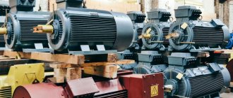
It is possible to significantly increase f only in relatively low-power UPSs from the point of view of power electronics. In high-power electrical energy converters - tens, hundreds and thousands of kilowatts, no matter how significantly the frequency can be increased. This is caused by the lack of transistors or thyristors that can quickly switch large loads while maintaining an acceptable level of energy loss. At most, it is possible to increase f to a thousand hertz, 400 Hz, or even lower. In addition, difficulties arise with cooling such converter units.
Losses in semiconductor switches depend on the voltage applied to them, the flow I and the switching frequency. As f increases, energy losses in semiconductor switches increase greatly. Therefore, the efficiency of the entire converter installation is significantly reduced. Hence, this method has not yet found application for powerful converters and is ineffective.
But even here a way out was found. All efforts were aimed at reducing the size and weight of the windings. In converters it can reach several tons. If you can significantly reduce its size, then you can wind up a certain number of turns and thereby reduce the dimensions of the magnetic core while maintaining the same value of the electromotive force.
The mass of copper windings mо depends on the total length of one turn lв, their number w, cross-sectional area Sв and the specific gravity of copper γm.
mo = lв∙w∙Sв∙γм.
The length of the coil lв is determined by its diameter dв, so we can rewrite the previous expression as follows:
mо = π∙dв∙w∙Sв∙γм.
In turn, the diameter dв determines the inductance T. Therefore, we cannot reduce it, since this will ultimately entail a decrease in the EMF, and this is not permissible.
It is also impossible to reduce the specific gravity of copper. It remains to reduce the cross-sectional area of the coil.
It, in turn, depends on the magnitude of the flowing I and the permissible current density j.
Sв = I∙j.
We also cannot reduce the current value, since it determines the power of the transformer at a given value of the electromotive force. There is only one way left - to increase the permissible density j.
Superconductors
This value for copper is on average in the range from 8 to 10 A/mm2. For the windings of electrical machines it will have a smaller value, and for installation wires or power lines it will have a greater value.
The value j shows what maximum current can be passed through a given conductor cross-section. For simplicity, we will accept the permissible value j = 10 A/mm2. This means that an I value of 1 A can be passed through a copper wire with a cross-section of 1 mm2. If this value is exceeded, it will overheat, which is unacceptable. The main reason is overheating of the insulation, which for electrical machines is more expensive than the cost of the wire itself. As the temperature rises, the service life of the insulation decreases sharply. This leads to premature repairs and costly rewinding of insulation.
If the conductor is forcibly cooled, then a larger I can be passed through the same Sb. It is in this way that the cross section Sb can be significantly reduced. So-called superconducting windings are used. They are in a special sealed container filled with liquid nitrogen. The boiling point of nitrogen is just over -195 °C. Liquid nitrogen is good because it is not explosive or toxic.
Thanks to the use of liquid nitrogen, the conductor resistance is reduced. This allows you to increase j by almost 30 times without overheating it. And accordingly, reduce the cross-sectional area of the winding wire, which in turn leads to a reduction in the weight of the electromagnetic device.
Let's summarize what was said above. To reduce the weight and dimensions of low- and medium-power UPSs, they increase the frequency of the supplied voltage to the transformer windings due to special circuit solutions. In power converters, this method is still difficult to implement due to the lack of semiconductor switches with acceptable switching characteristics. The only rational way is to use superconducting windings.
Now, I hope, you understand how a switching power supply works and why it has such a structure.
Reasons for power supply failure
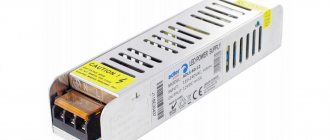
The power supply for a TV is a board on which there are transformers, a fuse, capacitors, a PFC unit, an inverter and a standby power supply; some models are also equipped with a diode bridge. Failure of each of the board elements can lead to complete failure of the TV. Faulty equipment can behave in different ways:
- The TV simply does not turn on and does not show any “signs of life”.
- There are several attempts to turn on, after which the TV turns off completely.
- Noise appears from the back wall of the TV: crackling, knocking or whistling.
- The indicator light does not light up.
- The TV randomly turns off.
- To achieve a normal signal, you can only turn the device off/on repeatedly.
- There is a delay in the image after turning on.
Problems with picture or sound quality are often not related to the power supply. The main symptom of a faulty power supply is the inability to turn on the TV.
There are actually many reasons for the failure of the power supply for a TV, and the breakdown is not always the fault of the user or improper operation of the device. The most common causes of malfunction are:
- Voltage fluctuations in the network. A sharp drop has a much more detrimental effect on the radio elements of the board than just increased or decreased voltage.
- Current surge. As a rule, modern apartments and houses are protected by automatic circuit breakers that turn off the power to electrical appliances when the current reaches a critical level. But a lightning strike during a thunderstorm can provoke a sharp and uncontrollable jump in current readings. Old LCD TVs are especially sensitive to this.
- Incorrect operating conditions. When working in humid conditions, moisture gets onto the TV board, and with sudden temperature changes, condensation forms on it. Moisture can cause failure of individual board elements.
- Short circuit. By analogy with a lightning strike, a short circuit provokes a sharp jump in critical current indicators. Unfortunately, machine guns do not always have time to protect equipment.
- Time factor. All BC boards have storage elements - capacitors. Over time, capacitors fail, swell, and this leads to malfunctions of the TV's power supply. It is impossible to influence this factor.
- Handicraft renovation. If the owner of the equipment has recently turned to uncertified technicians for help, there is a high probability that the breakdown was caused by their “repair”. After the work of unqualified specialists, “extra parts” may remain; they may make assembly errors and make incorrect connections.
Knowing the cause of the breakdown, it will be much easier to find the fault, since it will be clear where to look for the problem. But, before you start repairing the TV power supply, it is worth carrying out a full diagnosis and making sure that the fault is in the BC.
The design and principle of operation of the TV power supply
Before you begin troubleshooting the power supply, you need to understand its internal structure and operating principle. This element itself is a complex mechanism that regulates the supply of current and adjusts the voltage throughout the entire electrical appliance. It is thanks to it that normal energy consumption and the operation of the TV as a whole are ensured.
Nowadays, manufacturers are thinking through various options for completing a switching power supply. This is done in order to ensure safety and reliable transmission of electric current even under conditions of extreme voltage fluctuations. But often this does not justify itself, and adding additional parts not only does not make the design more reliable, but also creates additional weak points, and also complicates the repair of equipment. Therefore, it is best to use simple devices that are easier to operate. And it is advisable to have a connection diagram with you, with which you can understand the possible sources of the problem.
Main parts of the power supply:
- input voltage reduction and rectification system, consisting of a different amount of winding depending on the power of the current source;
- a special filter capacitor that smooths out differences in direct and current at the input;
- output voltage stabilization system, which includes a special microcircuit.
Based on the components included in the standard power supply, you can understand the principle of its operation, which consists of several successive stages:
- The input voltage coming from an external source is equalized to acceptable values for a particular electrical appliance.
- Then signals are generated, the approximate frequency of which varies between 10–100 kHz.
- Changing the pulse frequency to the required values.
- After this, the already received voltage is equalized and filtered directly inside the UPS.
Having carefully studied the main elements and understood the principle of operation of the device, you can begin troubleshooting and troubleshooting.
Diagnosing a TV malfunction
At the first symptoms of a breakdown, do not immediately disassemble the TV and remove the power supply. The fact is that the cause of the problem often lies in the outlet. First of all, you should check the presence of voltage in the network; there may be a fault in the wiring. Moreover, the presence of light or working sockets in other rooms does not mean anything, since the wiring can only be routed to one socket and pass through a separate circuit breaker. You can check the presence of voltage in the network using a conventional indicator.
If there is voltage, you should check its numerical value. This can be done using a regular multimeter. Almost all modern TVs are designed for an operating voltage range of 210-250 V. But in some cases, the voltage can drop to 190 or even 170 V. The TV won't turn on just because it doesn't have enough power. In this situation, you will either have to resolve the issue with the energy supply company or resort to purchasing a stabilizer.
The stabilizer will also help protect the TV from harmful power surges in the network.
If everything is fine with the power supply and voltage, the problem is really in the TV itself. And if it does not turn on, then everything lies in the malfunction of the power supply itself. What else you should pay attention to:
- Does the TV make any strange sounds - crackling, knocking, whistling or beeping?
- Is the indicator light on?
- Is the back of the TV getting hot?
- Does anything happen when the TV is connected to the network?
Next, you can begin to disassemble the TV and remove the power supply board from it to search for local faults.
Analysis and determination of the problem
The power supply is often integrated into the design of the TV. You need to remove the back cover secured with screws. The next step depends on the specific TV model. If the block is not immediately visible, then the part is hidden behind a protective casing - you just need to unscrew more screws.
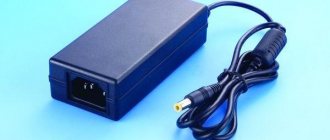
What does a power supply unit and its components look like?
The appearance of the power supply, located on the common board, is easy to distinguish from the rest. It is gray in color, looks like a square box, and is usually located on the edge of the power board. Capacitors and other components have a different shape. But they can easily be confused with transformers - they are also rectangular in shape, but painted yellow.
BP components:
- Standby power supply (standby indicator is on, 5V voltage is consumed). In other words, if it is broken, the indicator on the TV panel will not light up.
- Inverter - turns off the receiver immediately after turning it on. It is responsible for power supply, so if it breaks down it returns to standby mode.
- Capacitors - the problem is identified by swelling.
These breakdowns can be eliminated using power factor correction. Usually this diagnosis is carried out at a service center, but in general you can try to do it at home. In addition, such malfunctions are easy to fix - you need to purchase the necessary part and replace it using a blowtorch.
How to get to the board
Depending on the model and generation of the TV, the power supply may be located differently. In any case, you will need to remove the back cover from the TV, which is secured around the perimeter with small bolts. After removing the cover, the BC board will be visible - it can either be exposed or hidden behind an additional protective cover. The easiest way to determine the location of the power supply is by the incoming power connector, where the cable comes from the network - that’s where the board is located. If the BC is covered with protection, it will also have to be removed by unscrewing the bolt around the perimeter of the casing. Once the board is exposed, it can be removed. You can do this as follows:
- Unscrew the bolts used to secure the board.
- Disconnect the cable that can connect the power supply board to the secondary board.
- Disconnect all wires leading to the secondary board.
As a rule, one cable and one or two wires with special connectors are used to connect the BC and the secondary board.
Important!!! All manipulations should be performed after disconnecting the TV from the network. Working with a board that is live can be life-threatening!
How to connect?
Let's take a closer look at how to connect the power supply. In most cases, the amplifier is already built into the active antenna. But in passive it is not there. To connect it, you first need to assemble an antenna cable with a plug that will be intended for these purposes. Let's look at how to do this.
First you should prepare the cable itself, that is, strip it. To do this, use a sharp utility knife or scalpel to make a thin incision around the circumference at a distance of 1.5 cm from the edge of the cable
When performing this work, it is very important to be careful and try not to damage the hairs of the shielded braid located immediately under the insulating layer
After these steps are completed, the mentioned hairs must be carefully bent back, and the piece of foil located near them must be removed
Stepping back approximately 5 mm from the folded edge of the braid, you need to make another cut around the circumference. It is necessary to remove the inner insulating layer. After this, the cable, prepared for installation, should be inserted under the appropriate fasteners in the power supply box and tightened with screws.
We pay special attention to the fact that when a wire is connected, its metallized braid must have contact with a tinned pad, which is a mandatory design element of any power supply housing. If this is not done, then the antenna simply will not receive power.
It is also necessary to take into account the fact that the cable braid should under no circumstances come into contact with the central core of the wire itself. If this happens, a short circuit will occur and the module operation indicator will not function.
For information: if the power supply is correctly connected to the antenna cable itself, after making all the necessary settings, the TV usually shows many more channels than before.
Board diagnostics
As soon as the board has been removed, it is necessary to conduct an initial inspection for obvious damage. What to pay attention to:
- Are there any traces of burning? In some cases, certain elements may burn out, leaving behind soot.
- Solder debonding. Over time, poor-quality soldering can lead to one of the elements simply falling off.
- What do capacitors look like? Swollen capacitors are not always visible to the naked eye without using a multimeter, but if you manage to notice an objectively “inflated” capacitor, then it is obvious that it has failed.
- Integrity of connectors. Make sure that all connectors are not damaged. This applies to both the power input connector and the output connections to the secondary board. It is important that there are no traces of melting on the plastic input connector.
If there is nothing like this on the board, further search for the problem is carried out using a multimeter. First of all, you need to ring the fuse for integrity; if it does not ring, the cause of the malfunction is obvious. Replacing the fuse is the least of the problems that may arise when repairing a switching power supply with your own hands.
Under no circumstances should you install a replacement fuse with a higher rating, as this can lead to failure of more expensive elements. Also, you should not completely throw away the fuse, replacing it with a “twisted” one!
If the fuse is intact, you should check the capacitors, namely, measure the capacitance of each of them. You can also simply test them for integrity, since often the cause of capacitor failure is a break and breakdown. The capacitor rating can be found on the element itself. Even a 10% deviation from the nominal value requires a complete replacement of the elements.
Another way to test capacitors is to power the board from the mains and measure the board's output voltage. If it is below 5V, then the problem is in the capacitors.
If non-working, swollen or broken capacitors are detected, they must be replaced. Moreover, it is recommended to change all capacitors at once, since they usually fail one after another, and if one element is swollen, others will soon swell. You should also pay attention to the TV's power cable. It is enough to ring it for integrity. It happens that the problem lies in the connection of the cord and plug, as well as in the violation of the integrity of the wires.
Before diagnosing capacitors, they must first be discharged. This can be done using a regular light bulb, bringing it to the contacts of the capacitor. Otherwise, a short circuit may occur, which will lead to even greater damage, and there is also a risk of electric shock.
Detailed fault diagnosis
If the initial inspection of the board and checking for the most common breakdowns do not produce any results, you will have to resort to detailed diagnostics. To do this, you will need a circuit diagram for the TV's power supply, which can be downloaded from the manufacturer's official website. Next, using a tester (multimeter), the following checks are carried out:
- It is necessary to ring each element of the network (diodes, transistors, capacitors).
- We check the ballast resistance - the resistor for a break.
- You should also check the rectifier diodes, which often fail after a short circuit in the network.
Having identified a damaged board element, it will need to be replaced and a repair check performed.
TV PSU repair
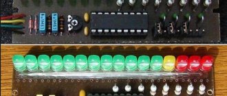
Before repairing a television power supply, it is useful to acquire its circuit diagram. The operating principle of these power supplies is the same as any other. But it produces multiple output voltages, which makes the diagnostic process a little more complicated.
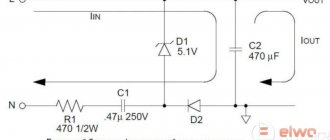
TV switching power supply circuit
Another difficulty is the presence of several protection systems for Uout deviations. from the norm. Because of them, the symptoms of many breakdowns look monotonous: the power supply does not show any signs of performance at all.
Today, the power supply circuit for almost any TV can be found on the Internet. A failure of the power supply is indicated by the inoperability of the LED, which usually operates in standby mode. If it burns, the cause is sought elsewhere.
As part of the diagnostics, the following elements are checked:
fuse. If there is no voltage behind it, the part is replaced;
ballast resistances. Their breakage is a possible cause of the malfunction;
smoothing capacitors of high-voltage and low-voltage rectifiers. Possible breakdown;
LC filter choke of the low-voltage rectifier. Possible breakage and interturn short circuit. If this model of power supply is rare, and it is not possible to find a similar inductor on sale, it can be rewound independently from a wire of the same cross-section
It is important to maintain the correct number of turns;
rectifier diodes. The semiconductors of the high-voltage converter fail more often because they operate under high voltage
Unlike the radio components listed above, diodes have to be soldered off for diagnostics.
It is impossible to check the functionality of the inverter microcircuit at home. Its malfunction is judged by indirect signs: if the normal state of all other elements is confirmed, but the power supply still does not work.
If the fuse is intact, check the voltage at the output of the high-voltage rectifier, looking for the following parameters:
- meaning;
- ripple amplitude (determined by an oscilloscope).
Normal values are from 280 to 320 V. At low values, the diodes are checked. A high ripple amplitude indicates a faulty smoothing capacitor or a broken rectifier.
If the voltage is normal, check the nature of the malfunction; two options are possible:
- The power supply does not turn on at all;
- tries to turn on, but is turned off by the locking system (reacts to low or high output voltage).
Popular articles Victory Day 2021
An oscilloscope is used again. Its input is connected to the output of the inverter key transistor connected to the primary winding of the transformer.
Ground the device to the “hot ground” of the power supply. If, when you turn on the TV with the power button, a series of pulses appears on the oscilloscope, this indicates attempts to start. This means that the device is blocked by one of the protections, for example, from exceeding the anode voltage on the kinescope. This helps narrow down the troubleshooting area.
If the power supply does not try to turn on, check the inverter elements. For example, measure the voltage at the collector of a key transistor. It should be the same as on the smoothing capacitor of the high-voltage rectifier.
The absence of voltage indicates a break in the primary winding of the pulse transformer. Having replaced the damaged radio components, they continue checking the power supply by turning on an incandescent light bulb with a power of 100 - 150 W instead of the fuse.
When you activate the power button on the TV, the light bulb behaves in accordance with the adapter malfunction:
- flashes and immediately goes out, the standby mode diode lights up, a raster is visible on the screen. The horizontal scan voltage needs to be checked. If it is too high, check and, if necessary, change capacitors and optocouplers;
- came on and went off, but the LED does not light up, and there is no grid on the screen. This indicates that the inverter is not working. Check the voltage on the smoothing capacitor of the high-voltage rectifier. If the value is too low, as already mentioned, a check of the diodes and this capacitor is required;
- burns especially brightly. In this case, the power supply is immediately disconnected from the network and the functionality of all elements is checked again.
Replacement of damaged elements
To repair the power supply board, you need to find replacements for all failed elements. You can buy diodes, capacitors and transistors at any radio electronics store or in specialized online stores. As soon as all the necessary elements are available, you should prepare for the work. For repairs you will need:
- Soldering iron with the ability to regulate the heating level.
- Screwdrivers.
- Wire cutters.
- Tweezers.
- Multimeter.
- Solder.
To remove a faulty element, you need to turn the board over and heat the solder, which fixes the “legs” of the element with the common track of the board. Once the tin is melted, the legs can be removed by pulling on the base of the element. Next, it is recommended to remove the remnants of old solder from the place of work and directly in the holes of the board under the legs. This will allow you to solder new elements more reliably. After inserting the legs of the new element into the holes, secure them with tin. This must be done extremely carefully, using a small amount of solder. Otherwise, the connection of adjacent elements may be affected.
When all repair work is completed, you can check the performance of the power supply. But before you check the TV's power supply for proper operation, you should carry out an additional check. To do this, simply remove the fuse and replace it with a regular incandescent light bulb. If, when power is applied to the board, the lamp filament becomes hot, then you can try connecting the board.
Checking the results of repair work
Upon completion of the repair, you need to mount the board back into the TV. To do this, all cables and connections are connected to the secondary board, and the power supply board itself is attached using one or two bolts. The first test should also be performed without the fuse, replacing it with an incandescent light bulb. If, when you connect the TV to the network, the lamp lights up and the TV itself operates normally, it means that the repair was performed correctly. All that remains is to replace the fuse, fix the board, cover it with a protective casing (if there was one) and secure the back cover of the TV.
But even after replacing the burnt-out board elements, the TV may not turn on. Failed elements during operation could lead to more serious damage. An experiment with a light bulb will reveal other faults:
- If the light comes on, but immediately goes out, and a characteristic raster appears on the screen, it is necessary to replace the optocoupler pairs.
- If the lamp lights up and goes out, but the TV indicator never lights up and nothing appears on the screen, you should look for the problem in the pulse generator area. It is recommended to check the voltage on the high voltage capacitors and recheck the integrity of the rectifier diodes.
- If the lamp burns brightly, there is a breakdown in the circuit, and high voltage is supplied to the area where there should be 5V. We check the output voltage of the transformer, and if it is damaged, the entire power supply must be replaced. If the transformers are intact, it is necessary to re-check and identify the “broken” element.
- If the lamp does not light, there is an open circuit. In this case, the integrity of each element is also re-checked by ringing with a multimeter.
The most unfavorable outcome is a break in the transformer winding. It will be extremely difficult to carry out such repairs, and most likely, the power supply itself will be replaced, which will cost several thousand rubles.
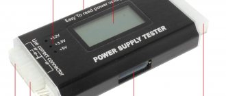
How to check for serviceability in practice?
In general, external diagnostics of possible malfunctions and breakdowns of the power supply is as follows.
If the appearance of the capacitors causes you any suspicion, then they must be immediately removed and replaced.
If you notice interruptions in the operation of the standby mode, you need to immediately check the voltage on the controlled zener diode. If there is no voltage at the output of this node or it is too low, therefore, the operating mode is disrupted.
In order to restore the functionality of the element, it is necessary to verify the functionality of all other parts of the circuit. To do this, you should unsolder one contact of the suspicious capacitor or resistor, remove all burnt elements completely and immediately replace them with new ones. If you see an area of poor-quality soldering, this area needs to be tinned with flux, and then make sure that the contacts are firmly fixed in the fastening area.
The restoration of the power supply circuit and the return to standby mode will be indicated by the appearance of a voltage of 5 V, as well as the blinking of the red light indicator on the front panel of the TV.
Please note that whenever you replace other suspicious elements, you must immediately check whether changes have occurred at the output of the power supply.
The fact that the functionality of the equipment has been returned can be judged by the TV turning on normally and the receipt of high-quality audio and video.
Do it yourself or contact a service?
Repairing a television power supply board is a rather labor-intensive process that is associated with high risks. Lack of sufficient knowledge and practical skills can lead to the fact that a small malfunction due to improper repair will turn into big problems. Also, without the proper knowledge and safety measures, an amateur repairman runs the risk of receiving an electric shock up to 220V, which can result in a critical threat to life and health. Therefore, if you have the slightest doubt about your own abilities and qualifications, you should contact the service center.
PSU repair is the most common type of repair performed by TV repair technicians. Therefore, they already know how to restore power supplies quickly and efficiently. The cost of repairs usually does not exceed 2,000 rubles, excluding the price of elements to be replaced. Moreover, in large service centers there will always be extra capacitors, transistors and diodes, so you don’t have to find out where to buy them, search all over the city or wait for an order from an online store.
How to prevent further damage
After successful repair, installation of the board in place and completed checks, care should be taken to ensure that the TV does not break down again. It is impossible to completely insure against breakdowns of complex equipment, but it is possible to eliminate the factors that disable the power supply:
- Solve the problem with voltage drops by installing a stabilizer.
- Install additional automatic protection against network overload and short circuits.
- Eliminate excessive humidity in the room where the TV is used.
- Make sure that you are using a working outlet and a quality extension cord, and that the TV's power cable and plug are not damaged.
- If any symptoms of a malfunction occur (noise, long startup time of the TV), do not start the problem and carry out repairs in a timely manner.
The only elements subject to the time factor are capacitors. Otherwise, it is much easier to prevent a malfunction than to repair it later.
Found a mistake? Select it and press ctrl+enter
- 100