In some situations, it is necessary to start the power supply without using a personal computer (PC). First of all, this is necessary to check the functionality of the component and the voltage at the terminals. Next, we will consider in detail the principle of operation and startup of the power supply without the use of a computer.
Important! Before starting the process, it is worth mentioning right away that starting the power supply (PSU) without using a PC or other load (at least a connected light bulb or cooler) can lead to its breakdown and electric shock, so all actions are performed on at your own risk.
Standard activation procedure
The operating principle of the power supply is based on converting electricity (mains voltage) to the value required for the functioning of the PC. Thanks to this, computer components can operate stably and not be affected by various interferences.
The startup process is as follows:
- first of all, the current is supplied to the filter , which is responsible for peaks, harmonics and interference in the electrical network;
- further, due to passage through the filter, the current stabilizes . Let's take for example a power value of 350V;
- then the current is supplied to the inverter , where it is converted into a variable value from 30 kHz to 55 kHz. Finally, current is supplied to all components of the PC through different taps, because equipment requires different voltages.
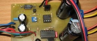
Checking with a special tester
How to check the computer's power supply for functionality if we have no knowledge of radio engineering and don't know how to solder? Limit yourself to simple voltage measurement? But, firstly, such a check will be incomplete. Secondly, using a multimeter requires understanding at least the basics of electrical engineering. But it turns out that you don’t have to make a tester - you can buy it. At least that's what they say. Let's check how true this information is and whether you can really buy a high-quality computer power supply tester for real money. We go online and start searching.
Power supply tester LCD
A relatively inexpensive and easy-to-use tester allows you to quickly measure voltages on the +12 V, +5 V, +3.3 V, +5 V SB and – 12 V buses, as well as the presence of a PG signal and the delay time for its appearance after the power supply starts. During measurement, the device independently monitors the voltage values and checks whether they fall within the permissible ranges. Using the Power supply tester, you can check the presence of voltages both on the main ATX connector and on the additional ones that supply the processor, video card, SATA and IDE peripherals.
In the photo the numbers indicate:
- 1 – socket for connecting the power cable for an 8-pin video card or 4-pin processor;
- 2 – socket for connecting a 6-pin video card power cable;
- 3 – socket for connecting the NGMD power cable;
- 4 – LED indicators of voltage presence on sockets 1, 2, 3, 7, 5;
- 5 – socket for connecting the power cable to SATA devices;
- 6 – LCD display;
- 7 – socket for connecting the power cable for IDE devices (MOLEX);
- 8 – socket for connecting the motherboard power cable (ATX).
Let's briefly look at the device's operating algorithm. We connect the main ATX power connector to the tester and, if necessary, the others that need to be checked. We plug in the power supply itself and it starts automatically. In this case, the LCD display of the tester displays the voltage values on all buses of the ATX connector and the delay time for turning on the PG signal.
If any parameter is out of range, an error message is generated for the corresponding channel. The presence of voltage on additional connectors is indicated by LED indicators. If they (connectors) are not connected, there is no indication.
Checking the computer power supply using a tester
Important! The device receives power from the ATX block and runs the power supply through it. Therefore, even if you need to test, say, a SATA connector, the ATX connector will have to be connected.
What can you say about this device? Convenient, simple, clear. It is inexpensive - around $10. But it measures voltages without load. Thus, it will not be possible to test the power supply 100%.
Kingwin KPST-02
This tester performs the same functions as the previous model, but it keeps the measurement results to itself, reporting only that such and such voltage is either normal or present. In addition, the device does not measure the delay time of the PG signal.
We work with it in the same way as with Power supply testerLCD. We connect the power supply pads, turn on the power supply to the network. It starts up, and we admire the light bulbs and wonder whether the voltage is normal or whether it is simply present, but it is not known whether it is within the permissible range.
It seems to work, but I personally wouldn’t trust the LEDs. Moreover, the description does not contain information that the device controls not only the presence, but also the magnitude of voltages. And if it is not specified, then either the marketers are asleep, which is unlikely, or no one controls anything. You will have to pick up a voltmeter and check all voltages. And if you need to tinker with a multimeter, why do you need such a tester? After all, he takes measurements without a power supply load. But there is also a plus - this tester costs half as much as the previous model.
How to turn on the power supply without a computer
The first power supplies for PCs were produced according to the AT standard. Thanks to this, the launch could be done without using a PC, i.e. directly. Now the units are produced in the new ATX standard, and idle starting is now harmful to them. They are equipped with SATA and Molex connectors for connecting hard drives and video cards. There are also 4-pin and 8-pin power supply for connecting the processor and 20 pin (older devices) or 24 pin (modern PCs are equipped) for the motherboard.
How to install a driver for an SM bus controller in Windows
To start the power supply, you need to know which contacts need to be closed; as a rule, (green) and COM connectors are used . Next, we will take a step-by-step look at the general steps to start without a PC.
First of all, you need to understand which cables carry what voltage in order to protect yourself. Power supply pinout diagram:
| Color | Voltage level in Volts | Connector number | Connector number | Voltage level in Volts | Color |
| orange | +3,3 | 1 | 13 | +3,3 | orange |
| orange | +3,3 | 2 | 14 | -12 | blue |
| black | grounding | 3 | 15 | grounding | black |
| red | +5 | 4 | 16 | Power on | green |
| black | grounding | 5 | 17 | grounding | black |
| red | +5 | 6 | 18 | grounding | black |
| black | grounding | 7 | 19 | grounding | black |
| grey | Power good | 8 | 20 | -5 | white |
| violet | +5 VSB | 9 | 21 | +5 | red |
| yellow | +12 | 10 | 22 | +5 | red |
| yellow | +12 | 11 | 23 | +5 | red |
| orange | +3,3 | 12 | 24 | grounding | black |
Instructions:
- First you need to disconnect the power supply from the network and other PC components;
- then unscrew the fastening bolts and carefully remove the power source from the system unit;
Please note that units equipped with 20 pin and 20+4 pin connectors should not be turned on without load. Otherwise, it may fail.
- to provide the load . The main thing is that the power supply does not work without load;
- Next, you need to short circuit PS_ON (green) and COM (black). To start, we use a paper clip or make a jumper. The jumper can be made from an ordinary piece of wire with stripped ends;
- We close the contacts, insert a paperclip or jumper into the PS_ON and COM connectors and start the power supply.
AT standard power supply , everything is a little different. Shorting the green and black contacts will not turn on the power supply without the motherboard. two combinations at once to start : blue - black and white - brown.
Adjusting the speed of computer or laptop fans
ATTENTION! When starting an AT standard power supply, you should be careful! The voltage at one of the closed contacts is 220 Volts!
Replacing the ATX block and repair tips
Replacing an ATX power supply is expected in the event of a breakdown of the old copy or in the case when the constituent elements of a personal computer have been replaced: more powerful video cards, processors, motherboards, more RAM. In the case of such a PC upgrade, the power supply becomes unable to supply power to all components of the PC. First of all, you need to remove the existing ATX element, install a new one and test its performance. You just need to know the basic concepts of circuit design and follow the instructions below:
- Necessary tools: standard size Phillips screwdriver.
- It is necessary to turn off the power to the personal computer - this process involves unplugging the power cord from the power supply.
- The next step is to remove the wall of the system unit; it is usually removed from the left side of the case by unscrewing several screws.
- Remove all accumulated dust from the computer components with a brush or vacuum cleaner. Please note that you should clean your computer from accumulated dust at least once every six months. Only after complete cleansing of dust can you proceed to the next steps.
- Disconnect all wires belonging to the power supply from other devices. Pay attention to the possible presence of special latches in the connectors. Do not pull out the connected wires abruptly.
- After disconnecting all the wires, unscrew the screws that secure the power supply to the computer's system power supply. This way the old power supply will be removed.
- To connect a new power supply, repeat all the steps exactly the opposite: attach it to the system unit, carefully connect all its wires to the necessary elements, connect an electrical cord with a power of 220 Volts to the power supply.
How to use a computer power supply
From an unnecessary power supply it is quite possible to make devices that are useful in everyday life. Next, let's look at how you can use a computer block.
Converting the power supply into an alternating voltage source
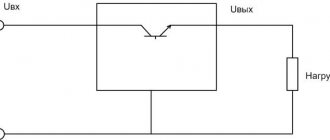
A constant voltage source from a computer power supply is quite a convenient thing. To do this, you will need to replace the resistance coils and remove the inductor. Thanks to this, you can adjust the voltage from 0 to 20V. If a standard voltage (12V) is required, then you need to install a thyristor regulator.
Converting a power supply into a charger
To convert the power supply into a charger, you will need to replace the Schottky diodes with ultra-fast ones. The main advantage of such a charger is that it is light in weight and dimensions. The disadvantages of this device are its sensitivity to overloads and short circuits. To prevent overloads and short circuits, it is necessary to construct a protection system.
Converting the power supply into a constant voltage source
First you need to determine what type of power supply is AT or ATX. Pulse (AT) engines operate exclusively under load, while ATX only needs to be closed to simulate the load, as described in the instructions above. In this case, the output voltage will be from 5 to 12 V. The final values will depend solely on the initial power of the unit.
Checking the startup of the power supply without a computer
This test of the computer power supply is convenient because it does not require the presence of the PC itself. All you need is a socket, a multimeter and a regular paper clip. So, we have an ATX power supply in our hands. We find a wiring harness ending in a 24-pin connector. This is the largest PSU connector, and it won’t be difficult to find.
On this block we find a green wire and, using an unbent paperclip inserted into the corresponding sockets, we connect it with any black one, thereby simulating the motherboard command to “turn on the power supply.”
These two contacts need to be closed
Now we connect the power supply to the network: if it is working properly, it should start. This will be clearly audible through the noise of the cooling fan running. But such a check cannot give a full or even partial guarantee that the power supply is fully operational. Therefore, we arm ourselves with a multimeter and move on to the next point.
Output voltage
If the power supply has passed the performance test by turning on after the manipulation described above, it makes sense to check the voltage at its output. And for this you can’t do without the help of a multifunctional electronic device - a multimeter. Or use a voltmeter.
For this purpose, the power supply is turned on in a way already known to us, after which we need to measure the voltage between any of the black wires and contacts of a certain shade:
- Black and pink - 3.3 V.
- Black and red - 5 V.
- Black and yellow - 12 V.
There may be minor deviations, which can be considered normal. But the values should not exceed 5% of the indicated values, up or down.
LEDs
Today, LED strips are widely used as a light source or decorative lighting, including in ordinary apartments. One of the voltages at the output of a computer power supply is 12V. This is exactly the indicator that the LED strip requires. You just need to make a few manipulations with the power supply, connect a strip to it, and economical lighting is ready!