Short circuit and separator device
Let's briefly talk about the design of the electromechanical devices shown above, this will be useful in explaining their operating principle. Let's start with the separator; its simplified drawing is presented below (Fig. 3 1).
Figure 3. 1) separator design; 2)short circuit design
Designations (part 1 separator design):
- A1 – insulating posts.
- B1 – rotating rods with knives installed in contacts.
- C1 is a spring mechanism that drives the rotary rods.
- D1 – platform.
- E1 – a cabinet with an electromagnetic “trigger” mechanism that releases a spring drive that separates the contact parts.
Both the devices themselves and the mechanics of their operation are not complicated. We have already mentioned that the separator is used when the voltage is removed from the network, that is, when the switches on the supply line are turned on. Consequently, there is no need to install special vacuum arcing contact chambers on the disconnectors.
Now let's look at the main design elements of the short circuit (Fig. 3 2):
- A2 – main (support) insulator rod.
- B2 – fixed rod with contact knives.
- C2 – spring drive.
- D2 – platform on which the short circuit is installed.
- E2 – cabinet for electromagnetic drive and current transformer.
- F2 is a movable grounded rod that closes the poles of the short circuit.
Structurally, the KZ-35 short circuiter, as well as other models that create an artificial interphase short circuit, have several differences from the device shown in the figure. Since a linear short circuit is simulated, the movable one is not connected to the ground, it is connected to another phase. Accordingly, the structure is equipped with another insulator-rack.
GENERAL INFORMATION
Currently, standard circuits of high-voltage substations without switches on the supply line have been developed. This makes it possible to reduce the cost and simplify the equipment while maintaining high reliability. Short circuiters and separators are used to replace circuit breakers on the high voltage side.
A short circuiter is a high-speed contact device that, based on a relay protection signal, creates an artificial short circuit in the network.
Outdoor short circuiters with a ShPK drive (short circuit drive in the cabinet) and a TShL 0.5 current transformer (bus current transformer, with cast insulation, accuracy class 0.5) are designed to create an artificial short circuit (two-phase for KZ-35 or to ground for KZ-110, KZ-220) in case of damage in the transformer. Under the influence of protection, a short circuit causes the switches installed at the supply ends of the lines to turn off.
The short circuiter is controlled by the ShKK drive, and the short circuiter is turned on automatically under the action of a spring mechanism when the drive is triggered by a relay protection signal. If necessary, the short circuiter can also be turned on manually. The short circuiter is switched off only during manual operation.
The separator is a disconnector that quickly turns off a de-energized circuit after a command is given to its drive. If in a conventional disconnector the shutdown speed is very low, then in a separator the shutdown process lasts 0.5-1.0 s. The separator disconnects damaged sections of the electrical circuit after the safety switch is turned off. The switch is triggered by an artificial short circuit created by a short circuit.
The separators are a two-column disconnector with grounding knives (ODZ); one ODZ-1A, ODZ-1B, two ODZ-2 or without them (OD), controlled by the SHPO drive (separator drive in the cabinet). Up to 110 kV inclusive, three poles of the separator are connected into a common three-pole device and controlled by one SHPO drive.
Separators for 220 kV are made in the form of three separate poles, each of which is controlled by an independent drive.
The separator is switched off automatically under the action of wound springs when a blocking relay or a shutdown electromagnet is activated, releasing the free release mechanism of the drive. The separator is switched on manually.
Designs of short circuiters and separators:
In Fig. 4.1.1. a short circuiter for a voltage of 35 kV KZ-35 is shown. Dimensions for a 110 kV short circuit are given in parentheses.
Rice. 4.1.1 Short circuiter KZ-35
A support insulator 2 is installed on the steel box 1. At the top of the support insulator there is a fixed contact 3, which is under high voltage. Movable grounded contact - knife 4 is mounted on shaft 5 of the short-circuit drive. Base 1 is isolated from the ground. Shaft 5 is acted upon by a drive spring, which is wound up in the disconnected state. To turn on, a command is sent to the drive electromagnet, which releases the mechanism latch. Under the action of the spring, the knife moves in a vertical plane and grounds contact 3. The turn-on time of such a short circuit is 0.15-0.25 s.
Rice. 4.1.2. Separator
The design of the OD-220 separator for a voltage of 220 kV is based on a two-column disconnector with blades 1 rotating in a horizontal plane, Fig. 4.1.2 The columns 2 are driven by a spring drive 3 with electromagnetic control. In the on position, the actuator springs are grounded. When a command is given, the spring is released and the contacts move apart in 0.4-0.5 s.
This is interesting: The zero in the electrical wiring is heating up - causes and solutions
The design and principle of operation of a short circuit.
Figure 1. Design
Figure 2. Buffer
Structurally, the short-circuiter (Fig. 1) consists of a base 3, an insulating column 2, on which a fixed contact 1 is fixed, and a grounding knife 8. The base 3 of the short-circuiter is unified and is a welded structure designed for installing an insulating column with a fixed contact. In the walls of the short-circuiter base there are bearings in which a shaft rotates with welded levers, two of which are connected to springs, and one lever interacts with an oil buffer, which serves to dampen the energy of the moving parts of the short-circuiter at the end of switching on. Each of the two springs, using a spring holder, is connected at one end to the shaft lever, and at the other to the base. The location of the springs at the base provides protection from precipitation and ice. The fixed contact consists of a contact holder and a contact. The contact holder is made in the form of a tray, which serves to attach the fixed contact to the insulating column. The oil buffer (Fig. 2) consists of a glass 6, inside of which there is a piston 3 and a rod 4. The return of the piston to its original position after the buffer is activated is ensured by spring 1. The buffer glass is filled with oil (AMG-10 GOST 6794-75). The oil level is controlled by a dipstick through the hole for bolt 5, and should be 30 - 50 mm above the piston above the piston in the upper extreme position. When the short circuiter is turned on, the lever hits the buffer rod 4 and moves the piston 3 down, as a result of which the oil flows into the upper cavity through the gap between the hole in the piston 3 and the screw 22. The end of the screw entering the piston hole is made of a cone, as a result of which the cross-section of the annular gap at The downward movement of the piston quickly decreases, which ensures effective braking. In the upper part of the buffer, to prevent impacts of the shaft lever on the flange, there are rubber washers with a steel washer superimposed on them, which are attached to the flange body with two bolts 5. The damping capacity of the buffer is adjusted by screw 2. The short-circuit knife is made of an aluminum alloy pipe, reinforced with a stiffener rib. A tire is welded into the groove of the pipe, to which a removable contact plate is attached using four bolts. The lower end of the knife is secured in the holder with two bolts. An insulating gasket is installed between the knife and the holder, which ensures isolation of the current-carrying circuit from the base of the short circuit. The contact terminal for connecting the grounding bus is fixed on an insulating gasket made of fiberglass. A current transformer of type TShL-0.5 is installed in the circuit of the grounding bus of the short-circuiter to ensure joint operation with the separator. After turning on the short-circuiter, the current flows through the following circuit: supply bus - fixed contact - grounding nom - flexible connection - grounding bus passed through the window of the current transformer - ground.
- Forward
Advantages and disadvantages
Opened separators and short circuits do not work very well in adverse weather conditions. Because of this, a certain structure with a contact system was created, placed in a chamber with SF6 gas.
A 35 kilowatt installation uses 2 poles. More powerful ones (110 kilowatts or more) use one pole. Typical short circuiters take a very long time to operate and therefore it is more advisable to use a device based on a powder charge. Its explosion sets the knife into motion.
It is important to know that when monitoring the condition of the devices, you first need to check the insulation on all parts. That's all I wanted to tell you about the principle of operation, design and purpose of short circuiters and separators
We hope the information was useful and understandable for you!
That's all I wanted to tell you about the operating principle, design and purpose of short circuiters and separators. We hope the information was useful and understandable for you!
We also recommend reading:
The modern organization of high-voltage power lines does not provide for the use of switches at node points connected to the supply lines. Instead, most substations use short circuiters and separators
This concept made it possible, while maintaining a high level of reliability, to significantly reduce the cost of equipment and, not least important, to simplify it. The structure of these electrical devices and the principle of operation will be described below.
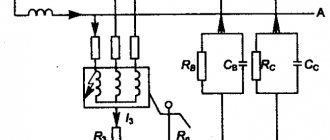
Joint operation of the short-circuiter with the separator
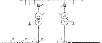
Now let's look at the OD-KZ combination using the example of a substation with two transformer groups powered from one incoming power line.
Example of a substation with OD-KZ
Designations:
- Vk1 – power switch VL (closed).
- Vk2, Vk3 – power protective switches on the low side (closed).
- Vk4 – sector switch (open).
- Kz1, Kz2 – short circuits (open).
- Od1, Od2 – separators (closed).
- Tr1, Tr2 – power transformers 220/10
To get an idea of how this circuit works, consider a situation where one of the transformers fails:
- Let's imagine that the insulation in Tr2 is broken, which leads to the formation of electric discharges that decompose the oil, which is detected by the gas relay and sends a corresponding signal to the control panel of the short circuiter Kz2.
- The signal received by the blocking relay causes it to operate. The mechanism is unlocked and the spring drive pushes the movable rod, as a result, two phases are closed.
- This turns on Vk1, which leads to the disconnection of the supply line and the de-energization of Tp1 and Tp2. A short circuit also causes a corresponding reaction of relay protection Tp2, it turns off Vk3 (the load is removed) and starts Od2. Since the latter has the slowest response speed, it is activated last when the overhead line and load are disconnected.
- After a certain delay, Vk1 reconnects the power line (the automatic restart system is triggered).
- Automatic transfer of reserve includes VK4.
As a result, only Tr1 works at the substation, from which both sections are powered.
Operating principle
A transformer is a device that is an electromagnetic device with 2 (or more) windings. This apparatus is primarily designed to convert alternating current from one voltage to another. Energy transformation occurs due to the magnetic field. Transformer booths are mainly used to conduct electricity over long distances, while at the same time separating and sending it to receivers, rectifiers, and amplifiers of various types of devices. The main component of the above device is a wire with windings. For high-quality operation, short circuiters and separators are installed in transformers, which regulate the serviceability of the device.
Briefly about the short circuiter
A short circuit is a device that creates an unnatural short circuit in electrical lines. Where are such devices used? First of all, the device is installed in transformers. It is used to ensure the disconnection of a faulty transformer after a short circuit has been created during the operation of relay protection of the line it supplies. After this, both the transformer and the line are disconnected from the mains.
How does a short circuit work? The device operates on 2 or 1 pole, depending on the voltage. Installations with 35 kV operate with two poles, and with a voltage of 110 kV or more, one pole is used. You can clearly examine the photo and diagram of the short circuit to understand what it consists of.
Short-circuit circuit diagram KZ-35: (1 – steel box; 2 – support insulator; 3 – fixed contact; 4 – moving grounded knife (contact); 5 – shaft).
The short-circuit gear has a spring that is responsible for turning on the moving knife to a fixed contact, which is currently energized. The relay protection pulses to start the drive, but is manually disabled. To avoid arcing and damage to the device, you need to increase the speed of the knife. In such designs, the short circuiter turns on in 0.15 - 0.5 s.
Briefly about the separator
A separator is a kind of disconnector that quickly turns off the network without current when it is commanded to do so. It can be distinguished from a disconnector due to the spring drive located on the separator. This device is turned on manually. Separators can also have a grounded leg on one side or on both. Let's look at the photo and diagram below to see what the separator consists of:
OD-220 separator diagram: (1 – 2-column disconnector with a knife that rotates; 2 – columns; 3 – spring drive).
Having familiarized ourselves with the diagram, let's see how the separator works. It turns off the circuit (without current) or the magnetizing current, but it is impossible to turn off the short circuit current that appeared during the start of the short circuit. And due to this nuance in the OD and SC circuits there is a blocking that prevents the separator from turning off, provided that current passes through the transformer. Where is this device used? In the transformer booth, to stabilize its operation.
Also, so that the separator does not turn off, a current relay is introduced into the design, which is connected directly to the current transformer located in the short circuit. After disconnecting the line, the relay will close the contact and the capacitor, which will cause it to work. Next, thanks to capacitor 2, a shutdown will occur.
Basic information about the short circuit (SC)
This electrical installation is used to create an artificial short circuit on the line. Hence the name of the separator.
As mentioned above, installations such as short circuiters can most often be found in transformer panels. What is it for?
After a short circuit has occurred on the electrical route, which is powered by an electrical transformer, it must be turned off. The short circuit is a key object in this process. After the circuit is closed, the device and the entire electrical route are disconnected from the power source.
On what principle does an electrical installation with a short circuit operate? Depending on the current power, the device can operate with one or two poles.
Mechanisms with a power value of up to 35 kV operate with 2 poles, while those with a power value of 110 kV use only one pole.
Above we have left for you a diagram and a photograph of the short circuit so that you can see all its components.
Short circuit and separator includes:
- metal short-circuit box;
- main insulator;
- fixed connector;
- movable short-circuit connector in the form of a knife with grounding;
- shaft.
The short circuit separator gear has a spring. It ensures the operation of a movable connector (knife) aimed at the stationary part of the mechanism, around which tension is generated.
The relay protection gives a push and the drive starts. But you will have to stop the relay yourself.
To prevent arcing and malfunction of the entire mechanism, it is necessary to improve the sharpness of the moving part (knife). In such devices, the short circuit begins its work in approximately 0.5 seconds.
Security measures.
When installing, testing, switching on, operating and repairing short circuiters, you must be guided by the current “Rules for the safe operation of electrical installations”. Servicing of short circuiters is permitted by persons who have passed the test of knowledge of PTE and PTB and have the appropriate qualification group. It is prohibited to perform operations with short circuits whose insulators are chipped or cracked. When setting up, testing, and checking the operation of the hydraulic buffers of the short-circuit, it is necessary to take precautions to prevent personnel from getting into the areas of movement of levers, rods, and knives. Do not allow foreign objects (keys, bolts, etc.) on the moving parts of the product. Do not allow impacts on the body and flanges of insulators during operation, adjustment, maintenance and repair. During testing, personnel are prohibited from standing on the short circuit
1.3. Outdoor disconnectors
Disconnectors for outdoor installation must have insulation designed to operate in adverse atmospheric conditions (pollution, moisture, snow), and also have increased mechanical strength, allowing operations with disconnectors in the presence of ice on the contacts. 10 kV disconnectors with vertical blade movement are made without ice breaking devices. Disconnectors above 10 kV are equipped with the following devices: for a disconnector of the RLNZ series (R - disconnector, L - linear, N - outdoor installation, 3 - with grounding blades), when disconnected, the blade first rotates 90° and then rises to the required distance; For a disconnector of the RONZ series (O - single-pole), the ice-breaking device is located in a fixed contact and is made in the form of a blade that can rotate 90° around its vertical axis. Horizontal rotary type disconnectors of the RLND series (D - two-column) are installed for voltages from 10 to 750 kV, the RND series - for voltages of 330-500 kV. Turning on and off the pole is done either by rotating one insulator on which the disconnector blade is installed, or by simultaneously rotating both insulators connected to each other by rods. Two-column rotary disconnectors of the SGF with a grounding switch are produced for voltages of 110, 150 and 220 kV (Ekaterinburg).
In Fig. Figure 1.4 shows a three-pole disconnector with a series version of the installation of poles with one grounding switch.
In Fig. Figure 1.5 shows a three-pole disconnector with a parallel installation option with two grounding electrodes. Rice. 1.5. Parallel installation of a three-pole disconnector (basic design) In Fig. 1.6. The most important parts of the disconnector are shown. The base of the disconnector 2 consists of a welded frame made of profile steel (221), rotary bases (70), and a transverse rod (68). Rotary bases are a closed structure that does not require maintenance during operation. Attached with studs for adjustment. Rotating heads (284) are installed on the insulators (201). This is also a closed structure that does not require maintenance and rotates 360 degrees. Current conductors (5 and 6) are a welded aluminum structure. The contact fingers (66) are made of copper-chrome-zirconium pseudo-alloy coated with silver. The direct contact (67) is made of copper coated with silver.
Rice. 1.6. Basic design of the disconnector High-voltage terminals (17) have a flat connecting surface in accordance with GOST 21242-75 with: - 4 holes for rated currents up to 1600 A; — 8 holes for rated currents above 1600 A. Drive mechanism (75) — motor or manual drive.
In Fig. 1.7 shows the main parts of the ground electrode. The grounding (79) is made of flexible connection made of copper, the grounding shaft (337) is made of galvanized pipe, the pipe (23) is made of aluminum. The contact pin (20) is also copper-chrome-zirconium metal ceramics coated with silver, and the grounded contact (18) is copper coated with silver. Drive mechanism (77) - motor or manual drive.
Rice. 1.7. Basic design of the grounding switch Disconnectors have independent drive mechanisms for the disconnector and the grounding switch. When switched off or on, the drive passes through a dead center before reaching the end position. This prevents spontaneous switching off or switching on of the disconnector or grounding switch: - during short circuits; — under external influences (storm wind or earthquake).
Rice. 1.8. explains the operation of the disconnector. The drive mechanism (75) transmits movement through the rod (37) to the rotating bases (70).
A crossbar (68) connects the two rotating bases of each pole. Consequently, the current conductors of both poles move simultaneously. Insulators (201) transmit torque to conductors 5 (contact side) and 6 (finger side). When switching, they rotate through an angle of 90°. When switched on, the contact (67) is securely pressed between the contact pins (66). This creates an electrical connection between the conductors. The current is transmitted through the socket contacts of the rotary heads (284) to the high-voltage terminals (17). By means of connecting rods (15), the movement of the leading pole is simultaneously transmitted to the other poles of the group.
Rice. 1.9 explains the operation of the ground electrode. The drive mechanism (77) transmits movement through the drive rod (71) to the grounding shaft (337). The grounding switch blade (23) turns up (on) or down (off). When switched on, the contact fingers (20) slide along the grounded contact (18). In the final “on” position they are pressed against the stop.
Rice. 1.9. Grounding switch Flexible grounding links (79) connect the blade (23) to the steel grounded frame of the disconnector. The disconnector and grounding switch are blocked according to the following principle: - the disconnector can be turned on only when the grounding switch is disconnected; — the grounding switch can only be switched on when the disconnector is switched off. Mechanical interlocks between the disconnector and the earthing switch are installed at the factory. Modernization is prohibited.
2.2. Designs of short circuiters and disconnectors
In Fig. Figure 2.1 shows a short circuit for a voltage of 35 kV KZ-35. Dimensions for a 110 kV short circuit are given in parentheses. Rice. 2.1 Short circuiter KZ-35 A support insulator 2 is installed on the steel box 1. At the top of the support insulator there is a fixed contact 3, which is under high voltage. Movable grounded contact - knife 4 is mounted on shaft 5 of the short-circuit drive. Base 1 is isolated from the ground. Shaft 5 is acted upon by a drive spring, which is wound up in the disconnected state. To turn on, a command is sent to the drive electromagnet, which releases the mechanism latch. Under the action of the spring, the knife moves in a vertical plane and grounds contact 3. The turn-on time of such a short circuit is 0.15-0.25 s.
Rice. 2.2 Separator OD-220
The design of the OD-220 separator for a voltage of 220 kV is based on a two-column disconnector with blades 1 rotating in a horizontal plane, Fig. 2.2. The columns 2 are driven by a spring drive 3 with electromagnetic control. In the on position, the actuator springs are grounded. When a command is given, the spring is released and the contacts move apart in 0.4-0.5 s.
1.4. Locking of disconnectors and switches
Turning off the disconnector when the rated current passes through it leads to a serious accident, possibly causing injury to people. The resulting arc is very mobile, quickly lengthens, which leads to bridging of the poles and the occurrence of a short circuit. To avoid such consequences, disconnectors are interlocked with switches using mechanical, mechanical and electromagnetic locking interlocks. In the first case, the disconnector drive lever is free only when the switch mechanism is in the disabled position. With such blocking, it is very difficult to connect the switch mechanism with many disconnector drives. In each individual case, you have to design your own blocking mechanism in relation to the design of the switchgear. Because of this, such blocking is rarely used. With mechanical locking, special locks are installed on the switch and the associated disconnector, which can be opened with a special key. The key is in the lock installed on the switch. It can only be removed from the lock when the switch is in the off state. The disconnector can only be turned on and off when the key is in its lock. Operations with other disconnectors are not possible, since there is no connection between the switch drives and the disconnectors. Electromagnetic locking is more advanced, fig. 1.10. To operate the disconnector, the key in the form of an electromagnet (Fig. 1.10.a) must be inserted into the lock (Fig. 1.10.6). The ends of the coil 2 of the electromagnet are brought out to the pin contacts 3. If the switch associated with this disconnector is turned off, then voltage is supplied to the coil 2 through its opening block contacts and sockets 4. When you press the ring 1, the armature 5 is lowered and is engaged under the influence of electromagnetic force with locking plunger 6. As a result, part 8 of the disconnector drive will be released, and pins 7 will fit into groove A of the key, preventing it from being removed from the lock. To lock all disconnectors, one key is sufficient for the entire switchgear.
Rice. 1.10. Electromagnetic lock with key
- Forward
2.3. Operating principle of separators and short circuiters
As an example of the use of short circuiters and separators in Fig. 2.3. The diagram of power supply from one line of two transformer groups T1 and T2 is shown.
220kV
Rice. 2.3. Switching diagram with separators and short-circuiters In addition to the high-speed short-circuiters KZ-1 and KZ-2, the circuit includes separators OD-1 and OD-2, which are closed during normal operation. Suppose, due to deterioration of the insulation of transformer T1, electrical discharges occur inside it, which lead to the decomposition of oil and the release of gas. Gas bubbles rising upward trigger the gas relay. The signal from this relay turns on the short circuit and an artificial short circuit occurs in the circuit. Under the action of the short-circuit current, the protection switch B1 is triggered and both transformers T1 and T2 are de-energized. Using the relay protection of transformer T1, switch B2 is also turned off, after which, after a certain delay, separator OD1 is turned off. Then, since the artificial short circuit mode was turned off, switch B1 is turned on again, that is, the automatic reclosure of this switch is triggered. If before the accident switch B4 was turned off, then after switching on switch B1 it can be turned on, that is, the ATS (automatic transfer switch) will work. In this case, power will be restored to consumers on the 10 kV buses of the first transformer group. The efficiency of such a scheme is higher, the more rated mains voltage. This effect is achieved due to the absence of switches on the 35-220 kV side, as well as batteries and compressor units. The substation area is reduced. Construction time is reduced.