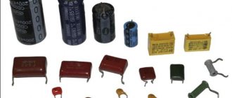
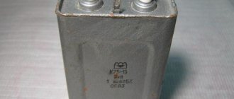
Capacitors
– electronic components consisting of two conductor plates and a dielectric located between them. There are many types of capacitors that have a similar design, but differ in the materials from which the plates and dielectric layer are made, and in their functions in electronic circuits. The type of product is determined by the shape, color, and markings on the case.
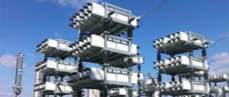
High voltage capacitors
High-voltage devices (voltage multipliers, Marx generators, Tesla coils, high-power lasers, etc.) use high-voltage capacitors that differ in design from low-voltage capacitors. They are used in circuits with voltages greater than 1600 V. Some types of high-voltage electronic devices:
- K75-25 – pulse models used in circuits with voltages up to 50 kV. Their capacitance is 2-25 nF. Due to the ability to work with currents with a frequency of 500 Hz, they are effective in Tesla spark coils.
- K15-4. This type of capacitor can be identified by its green cylindrical body. They have a small capacitance and are used in Marx generators, old televisions, voltage multipliers and other high-voltage, low-frequency circuits.
- K15-5. Ceramic parts of brick color, compact dimensions, disk shape. The maximum voltage is 6.3 kV, used in high-frequency filters.
Announcements on NN.RU - Construction
Milan kitchen table new with free delivery to your doorstep in the city of Nizhny Novgorod Dzerzhinsk. Size: 1154*752*756 mm frame: legs. Price: 4,500 rub.
OPGS in bags and in bulk! Seven days a week! Delivery throughout the city and region! Any form of payment! Price: 1,350 rub.
Set of kitchen corner table stools new free delivery within the city of Nizhny Novgorod Dastorg factory offers - kitchen corners with. Price: 8,050 rub.
I will deliver a new ash orchid set for free around the city of Nizhny Novgorod, Dzerzhinsk. There are other colors and models from RUB 5,000 on sale. Price: 7,500 rub.
There is a real construction boom in Nizhny Novgorod. In every district of the city, new houses are appearing that will be rented out in the coming years.
Ceramic capacitors
Ceramic and glass-ceramic capacitors with a solid inorganic dielectric layer are available in high-voltage and low-voltage versions. They are compact in size and reliable. Widely in demand in computing, household, medical, military equipment, and transport. Based on their rated voltage, they are divided into high- and low-voltage.
The following ceramic capacitors are produced by design type:
- KTK – tubular;
- KDK – disk;
- SMD – surface and others.
To make ceramic capacitors, they do not use baked clay, but materials similar to it in structure - ultraporcelain, tikond, ultrasteatite. The lining is a silver layer. Ceramic and glass-ceramic devices are used in circuits in which frequency characteristics, low leakage losses, compact dimensions, and low cost are important.
Preparatory activities
The first thing to note is that the procedure for replacing capacitors is a very delicate, almost surgical procedure that will require appropriate skill and experience. If you are not confident in your abilities, then it is better to entrust the replacement to a specialist.
If you have the necessary experience, make sure that in addition to it you have the appropriate equipment.
Replacement capacitors The most important element. These components differ from each other in two key parameters: voltage and capacitance. Voltage represents the operating voltage of the element, capacitance represents the amount of charge that the capacitor can hold. Therefore, when choosing new components, make sure that their voltage is equal to or slightly higher than the old ones (but in no case less!), and that the capacity exactly matches the failed ones.
Soldering iron This procedure requires a soldering iron with a power of up to 40 W with a thin tip. You can use a soldering station with power adjustment. In addition, be sure to purchase a suitable flux for your soldering iron.
Steel needle or piece of wire A sewing needle or piece of thin steel wire will be needed to clean and widen the hole in the board for the capacitor legs. It is not advisable to use thin objects made of other metals, as they may be seized by the solder, which will create additional difficulties.
Once you are sure that the inventory meets the requirements, you can proceed directly to the replacement procedure.
Paper and metal-paper capacitors
In paper capacitors, the foil plates are separated by a dielectric made of capacitor paper. These parts are used in both high frequency and low frequency circuits. They are not popular due to their low mechanical strength. A more durable option is a metal-paper part, in which a metal layer is sprayed onto the paper.
Paper and metal-paper capacitors are produced in a wide range of capacities and rated voltages. Metal-paper options benefit in terms of compact design and lose in terms of stability of insulation resistance. An additional advantage of metal and paper products is the ability to self-heal electrical strength in isolated cases of paper breakdown.
Design and purpose of capacitors
This element of the electrical circuit consists of two plates (plates). The plates are positioned relative to each other so that there is a gap between them. When a capacitor is connected to an electric current circuit, charges accumulate on the plates. Due to the physical gap between the plates, the device has low conductivity.
Attention! This gap can be air or filled with a dielectric. The following dielectrics are used: paper, electrolyte, oxide films
The main feature of such a two-terminal network is the ability to accumulate electric field energy and instantly transfer it to the load (charge and discharge).
The first prototype of the container was the Leyden jar, created in 1745 in the city of Leiden by the German von Kleist. The jar was lined with copper foil inside and out. This is how the idea of creating covers came about.
The graphic designation of a two-terminal network on diagrams and drawings is two vertically located lines (like plates) with a gap between them.
Electrolytic capacitors
Electrolytic capacitors are characterized by increased energy intensity and are used in AC and DC circuits. In them, the dielectric is a metal oxide layer created by an electrochemical method. It is located on a plus cover made of the same metal. The other cover is liquid or dry electrolyte. Metal – aluminum, niobium or tantalum.
Fixed capacitors are obsolete. They were replaced by parts with variable electrical capacity. The most common electrolytic capacitors are the tuning type. Their capacitance changes when adjusted, but remains constant during operation of the circuit. Thanks to the sealed housing and solid semiconductor, the products are shelf stable and can be used at low temperatures (down to -80°C) and high frequencies.
Why do electrolytic capacitors explode?
The most common reason why an electrolytic capacitor explodes is excess voltage between the capacitor plates. It is no secret that in many Chinese-made devices, the maximum voltage parameter exactly corresponds to the applied voltage. According to their idea, capacitor manufacturers did not foresee that when a capacitor is normally included in an electrical circuit, the maximum voltage will be supplied to its contacts. For example, if the capacitor says 16V 100uF, then you should not connect it to a circuit where 15 or 16V will be constantly supplied to it. Of course, he will withstand such abuse for some time, but the safety margin will be practically zero. It is much better to install such capacitors in a circuit with a voltage of 10–12V, so that there is some voltage reserve.
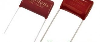
Film and metal film capacitors
Polystyrene film products are in demand in pulsed circuits, with direct or high-frequency alternating current. Such products are produced with foil coverings or with a film dielectric, on which a thin metallized layer is applied. Polycarbonate, Teflon, polypropylene, and metallized paper are used to make film dielectrics. Capacitance range – 5 pF-100 µF. High-voltage versions of film capacitors are very popular - up to 2000 V.
Various types of film capacitors are available, which differ in:
- placement of dielectric layers and plates - axial and radial;
- case materials - polymer and plastic; models without a case with epoxy coating are produced;
- shape – cylindrical and rectangular.
The main advantage of such products is their ability to self-heal, protecting them from the possibility of premature failure. Other advantages are good electrochemical characteristics, thermal stability, and the ability to withstand high loads at alternating current. Due to the properties listed above, film and metal film products are used in measuring technology, radio electronics, and computer technology.
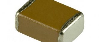
CHIP capacitors
Also called SMD capacitors. These radio components are designed for surface mounting. Types of leadless capacitors:
Chip capacitors have compact dimensions, a standardized body shape, and characteristics that largely coincide with multilayer capacitors. They are used in printed circuit boards both individually and in sets.
Table of capacitor analogues
Write in the comments what analogues of foreign or domestic capacitors you know and we will add them to the table.
Correct selection of a capacitor ensures the operation of the electrical circuit in strict accordance with the technical specifications. For some structures, in addition to the container, it is necessary to ensure certain dimensions and resistance to adverse external influences. This publication will help you find suitable products in the assortment of specialized stores.
Divisions of capacitors with the possibility of changing the capacitance
According to this parameter, parts in this category are divided into:
Specific names determine the main design features and intended purpose. A typical permanent capacitor is created from conductive plates, rolled into a roll to reduce size. A dielectric is installed between them. The assembly is placed in a metal case or filled with polymer to provide the necessary security parameters.
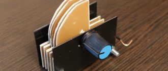
In variable and tuning models, sets of mechanically driven plates are used. By changing the position of the working elements, the required capacity value is established. Each product is designed for a specific range of operating parameters. Such capacitors are used to fine-tune the oscillatory circuit. They are installed in radio-electronic units to regulate individual operating parameters during operation.
Properties and parameters of capacitors
The main parameter of devices in this category is capacity (C). It determines the storage properties of the product. The operating principle is based on the transfer of electrons to the corresponding plate when a power source is connected. Depending on the polarity, positive (negative) charges appear on the corresponding electrode.
The size of the capacity depends on several parameters:
- plate sizes (plating area);
- distances between them;
- dielectric properties of the material in the gap.
For your information. Capacity is indicated in multiple units. Example: pF or pF is picofarad (10-12 farads).
The voltage of a flat capacitor is calculated using the formula:
Where:
- q – charge;
- e – dielectric constant;
- S – working area.
From this expression it is easy to conclude about the mutual influence of electrical and structural parameters. Capacity is determined as follows:
Where:
- d – distance between plates;
- U – voltage.
For convenience, a specific indicator is used:
where V is the volume of the product.
Based on it, a conclusion is drawn about how effectively the capacitor performs its main functions. With a high specific capacity, discharging takes longer if a similar load is connected.
The accuracy class or percentage deviation indicates the tolerance from the nominal capacity (values are indicated ± in%):
Consumer parameters of a dielectric are characterized by electrical strength. As a rule, the voltage rating in long-term operating mode for certain conditions is indicated on the product body, taking into account the ranges:
- temperature;
- relative humidity;
- pressure.
Detailed documentation indicates the breakdown voltage.
Inductance (self) changes the field strength of the capacitor. This reactive component “helps” the product discharge faster or slower compared to the design speed of the process. Such parasitic influences distort the operating characteristics of the oscillatory circuit. They must be taken into account when designing frequency-dependent circuits.
Losses are estimated by the electrical resistance of the insulating layers. If you connect the multimeter accordingly, you can clarify the actual leakage current. This parameter is measured over a certain period of time. It should be remembered that resistance depends on temperature and humidity.
For your information. Mica capacitors will discharge more slowly than paper capacitors under equal conditions, since the leakage currents differ by an order of magnitude.
For a comprehensive comparison of different parts in this category, stability is checked. This indicator characterizes the constancy of operating parameters. As a rule, the influence of temperature is taken into account. The specialized coefficient (TKE) shows the corresponding changes with an increase (decrease) of 1°C.
How to discharge a capacitor to minimize residual voltage? The answer to this question will help to obtain the study of absorption processes in the dielectric layer. The corresponding parameters are characterized by a correction factor (Ka). It increases with increasing temperature.
Replacing faulty capacitors
Warning! You take further actions at your own peril and risk! We do not bear any responsibility for possible damage to the board!
This procedure takes place in three stages: desoldering old capacitors, preparing the site, installing new elements. Let's look at each in order.
Stage 1: Desoldering
To avoid failures, it is recommended to remove the CMOS battery before starting manipulations. The procedure goes like this.
- Locate the location of the faulty capacitor on the back of the board. This is a rather difficult moment, so be extremely careful.
- Having found the fastening, apply flux to this place and heat one of the legs of the capacitor with a soldering iron, carefully pressing on the corresponding side of the element. Once the solder melts, the leg will be free.
Be careful! Prolonged heating and excessive force during this action can damage the board!
- Repeat these steps for the second leg and carefully remove the capacitor, making sure that no hot solder gets on the motherboard.
If there are several capacitors, repeat the above procedure for each. Having pulled them out, proceed to the next step.
Stage 2: Preparing the seat
This is the most important part of the procedure: competent actions determine whether you can install a new capacitor, so be extremely careful. In most cases, when removing elements, solder gets into the leg hole and clogs it. To clear the area, use a needle or piece of wire as follows.
- From the inside, insert the end of the tool into the hole, and from the outside, carefully heat the place with a soldering iron.
- Using gentle rotating movements, clean and widen the hole.
- If the hole for the leg is not clogged with solder, just carefully enlarge it with a needle or wire.
- Clean the capacitor seat from excess solder - this will avoid accidental shorting of inconspicuous conductive paths, which can damage the board.
After making sure that the board is prepared, you can move on to the last stage.
Stage 3: Installation of new capacitors
As practice shows, most mistakes are made at this step. Therefore, if the previous stages have tired you, we recommend taking a break and only then proceeding to the final part of the procedure.
- Before installing new capacitors on the board, they must be prepared. If you are using a used version, strip the legs of old solder and carefully warm them with a soldering iron. For new capacitors, it is enough to treat them with rosin.
- Insert the capacitor into the seat. Make sure its legs fit freely into the holes.
- Coat the legs with flux and carefully solder them to the board, taking all precautions.
Be careful! If you reverse the polarity (soldering the positive pin to the negative pin), the capacitor may explode, destroy the board, or cause a fire!
After completing the procedure, let the solder cool and check the results of your work. If you followed the above instructions exactly, there shouldn't be any problems.
Alternative replacement option
In some cases, in order to avoid unnecessary heating of the board, you can do without soldering the faulty capacitor. This method is rougher, but is suitable for users who are not confident in their abilities.
- Instead of desoldering the element, it should be carefully broken off from the legs. To do this, try to swing the faulty part in all directions and, with careful pressure, break it off first from the first contact, and then from the second. If during the process one of the legs comes out of place on the board, it can be replaced with a piece of copper wire.
- Carefully remove the top part of the remaining legs with traces of attachment to the capacitor.
- Prepare the legs of the new capacitor as in step 3 of the last stage of the main method and solder them to the remains of the legs of the old one. The picture should look like this.
The capacitor standing at an angle can be carefully bent to a vertical position.
That's all. Finally, we would like to remind you once again - if you think that you cannot cope with the procedure, it is better to entrust it to the master!
We are glad that we were able to help you solve the problem. In addition to this article, there are 12,720 more instructions on the site. Add the Lumpics.ru website to your bookmarks (CTRL+D) and we will definitely be useful to you. Thank the author and share the article on social networks.
Describe what didn't work for you. Our specialists will try to answer as quickly as possible.
Abbreviations
The standard version includes permanent (K) and trimmer (CT) capacitors. Variables (CV) are created according to individual orders. Below are individual parameters according to GOST 13 453-68.
Dielectric material:
- B – paper;
- MP – metal/film combination;
- C – mica;
- E – electrolyte;
- K – ceramics.
According to the degree of protection from external influences, a hermetic (G) version and a pressurized housing (O) are distinguished.
Design:
- M – monolith;
- B – barrel;
- D – disk;
- C – sectional option.
Operating mode (current):
- I – pulse;
- U – universal (pulse, constant and variable);
- H – only constant;
- P – variable/constant.
Other features:
- U – capacitor designed to operate in the VHF range;
- M – compact dimensions;
- T – preservation of technical parameters is ensured when the temperature rises;
- B – the product is suitable for installation in high voltage networks.
The standard designation indicates (by position number):
- type of capacitor (K, CT or KP);
- code for dielectric and basic parameters (K10 ceramics for voltage up to 1600 V);
- current operating mode;
- production series or other technological designation.
Additional information:
- You can select products by combined (numeric and alphabetic) color marking;
- Abbreviations are applied to the compact body (instead of 1000uF - 1000m);
- The accuracy class is indicated in Latin font (U is ±);
- The rated voltage (Q-160V) is encoded in the same way.
Electronics for everyone
If you connect a resistor and a capacitor, you get perhaps one of the most useful and versatile circuits.
Today I decided to talk about the many ways to use it. But first, about each element separately:
The resistor's job is to limit the current. This is a static element whose resistance does not change; we are not talking about thermal errors now - they are not too large. The current through the resistor is determined by Ohm's law - I=U/R
, where U is the voltage at the resistor terminals, R is its resistance.
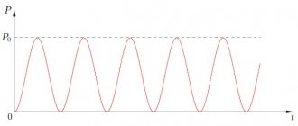
The capacitor is a more interesting thing. It has an interesting property - when it is discharged, it behaves almost like a short circuit - the current flows through it without restrictions, rushing to infinity. And the voltage on it tends to zero. When it is charged, it becomes like a break and the current stops flowing through it, and the voltage across it becomes equal to the charging source. It turns out an interesting relationship - there is current, no voltage, there is voltage - no current.
To visualize this process, imagine a balloon... um... a balloon that is filled with water. The flow of water is a current. Water pressure on elastic walls is the equivalent of stress. Now look, when the ball is empty - water flows freely, there is a large current, but there is almost no pressure yet - the voltage is low. Then, when the ball is filled and begins to resist pressure, due to the elasticity of the walls, the flow rate will slow down, and then stop altogether - the forces are equal, the capacitor is charged. There is tension on the stretched walls, but no current!
Now, if you remove or reduce the external pressure, remove the power source, then the water will flow back under the influence of elasticity. Also, the current from the capacitor will flow back if the circuit is closed and the source voltage is lower than the voltage in the capacitor.
Capacitor capacity. What is this? Theoretically, a charge of infinite size can be pumped into any ideal capacitor. It’s just that our ball will stretch more and the walls will create more pressure, infinitely more pressure. What then about Farads, what is written on the side of the capacitor as an indicator of capacitance? And this is just the dependence of voltage on charge (q = CU). For a small capacitor, the voltage increase from charging will be higher.
Imagine two glasses with infinitely high walls. One is narrow, like a test tube, the other is wide, like a basin. The water level in them is tension. The bottom area is the container. Both can be filled with the same liter of water - equal charge. But in a test tube the level will jump by several meters, and in a basin it will splash at the very bottom. Also in capacitors with small and large capacitance. You can fill it as much as you like, but the voltage will be different.
Plus, in real life, capacitors have a breakdown voltage, after which it ceases to be a capacitor, but turns into a usable conductor
How quickly does a capacitor charge?
Under ideal conditions, when we have an infinitely powerful voltage source with zero internal resistance, ideal superconducting wires and an absolutely flawless capacitor, this process will occur instantly, with time equal to 0, as well as the discharge.
But in reality, there is always resistance, explicit - like a banal resistor, or implicit, such as the resistance of wires or the internal resistance of a voltage source. In this case, the charging rate of the capacitor will depend on the resistance in the circuit and the capacitance of the capacitor, and the charge itself will follow an exponential law
.
And this law has a couple of characteristic quantities:
- T is the time constant
, this is the time at which the value reaches 63% of its maximum. 63% didn’t come about here by chance, it’s directly tied to this formula VALUET=max—1/e*max. - 3T - and at three times the constant the value will reach 95% of its maximum.
Time constant for RC circuit T=R*C
.
The lower the resistance and lower the capacitance, the faster the capacitor charges. If the resistance is zero, then the charging time is zero.
Let's calculate how long it will take for a 1uF capacitor to be charged to 95% through a 1kOhm resistor:
T= C*R = 10-6 * 103 = 0.001s 3T = 0.003s After this time, the voltage on the capacitor will reach 95% of the source voltage.
The discharge will follow the same law, only upside down. Those. after T time, only 100% - 63% = 37% of the original voltage remains on the capacitor, and after 3T even less - a measly 5%.
Well, everything is clear with the supply and release of voltage. What if the voltage was applied, and then raised further in steps, and then discharged in steps as well? The situation here will practically not change - the voltage has risen, the capacitor has been charged to it according to the same law, with the same time constant - after a time of 3T its voltage will be 95% of the new maximum. It dropped a little - it was recharged and after 3T the voltage on it will be 5% higher than the new minimum. What am I telling you, it’s better to show it. Here in multisim I created a clever step signal generator and fed it to the integrating RC chain:
You see how it wobbles. Please note that both charge and discharge, regardless of the height of the step, are always of the same duration!!!
To what value can a capacitor be charged? In theory, ad infinitum, a sort of ball with endlessly stretching walls. In reality, sooner or later the ball will burst, and the capacitor will break through and short-circuit. That's why all capacitors have an important parameter - the maximum voltage
. On electrolytes it is often written on the side, but on ceramic ones it must be looked up in reference books. But there it is usually from 50 volts. In general, when choosing a condenser, you need to ensure that its maximum voltage is not lower than that in the circuit. I will add that when calculating a capacitor for alternating voltage, you should choose a maximum voltage 1.4 times higher. Because on alternating voltage the effective value is indicated, and the instantaneous value at its maximum exceeds it by 1.4 times.
What follows from the above? And the fact is that if a constant voltage is applied to the capacitor, it will simply charge and that’s it. This is where the fun ends.
What if you submit a variable? It is obvious that it will either charge or discharge, and current will flow back and forth in the circuit. Movement! There is current!
It turns out that, despite the physical break in the circuit between the plates, alternating current easily flows through the capacitor, but direct current flows weakly.
What does this give us? And the fact that a capacitor can serve as a kind of separator to separate alternating and direct current into the corresponding components.
Any time-varying signal can be represented as the sum of two components - variable and constant.
For example, a classical sinusoid has only a variable part, and the constant is zero. With direct current it is the opposite. What if we have a shifted sinusoid? Or constant with interference?
The AC and DC components of the signal are easily separated! A little higher, I showed you how a capacitor is charged and discharged when the voltage changes. So the variable component will pass through the conder with a bang, because only it forces the capacitor to actively change its charge. The constant will remain as it was and will be stuck on the capacitor.
But in order for the capacitor to effectively separate the variable component from the constant, the frequency of the variable component must be no lower than 1/T
Two types of RC chain activation are possible: Integrating and differentiating
. They are also a low-pass filter and a high-pass filter.
The low-pass filter passes the constant component without changes (since its frequency is zero, there is nowhere lower) and suppresses everything higher than 1/T. The direct component passes directly, and the alternating component is quenched to ground through a capacitor. Such a filter is also called an integrating chain because the output signal is, as it were, integrated. Do you remember what an integral is? Area under the curve! This is where it comes out.
How is the constant component calculated here? And you can’t tell by looking at it, but we must remember that any periodically signal is expanded into a Fourier series
, turning into the sum of a constant component and a pack of sinusoids of different frequencies and amplitudes.
The high pass filter works in reverse. It does not let in the constant component (because its frequency is too low - 0) - after all, the capacitor for it is equivalent to a break, but the variable gets through the condenser without problems.
And it is called a differentiating circuit because at the output we get the differential of the input function, which is nothing more than the rate of change of this function.
- In section 1, the capacitor is charged, which means current flows through it and there will be a voltage drop across the resistor.
- In section 2, there is a sharp increase in the charging speed, which means the current will sharply increase, followed by a voltage drop across the resistor.
- In section 3, the capacitor simply holds the existing potential. No current flows through it, which means the voltage across the resistor is also zero.
- Well, in the 4th section the capacitor began to discharge, because... the input signal has become lower than its voltage. The current has gone in the opposite direction and there is already a negative voltage drop across the resistor.
And if we apply a rectangular pulse to the input, with very steep edges, and make the capacitance of the capacitor smaller, we will see needles like these:
At the top there is an oscillogram of what is at the input, below is what is at the output of the differential circuit. As you can see, there are powerful surges at the fronts. This is understandable, in this place the function changes sharply, which means the derivative (rate of change) of this function is large, in flat areas the signal is constant and its derivative, the rate of change, is equal to zero - zero on the graph.
And if you drive a saw into the differentiator, the output will be...
rectangle. Well, what? That's right - the derivative of a linear function is a constant, the slope of this function determines the sign of the constant.
In short, if you are currently taking a math course, then you can forget about the godless Mathcad, disgusting Maple, throw the matrix heresy of Matlab out of your head and, taking out a handful of analog loose stuff from your stash, solder yourself a truly TRUE analog computer. The teacher will be shocked
True, integrators and differentiators are usually not made using resistors alone; operational amplifiers are used here. You can google for these things for now, interesting thing
And here I fed a regular rectangular signal to two high- and low-pass filters. And the outputs from them to the oscilloscope:
And this is what happened on the oscilloscope:
Here's a slightly larger section:
>
As you can see, on one the constant component was cut off, on the other the variable.
Okay, we're getting off topic.
How else can you use an RC circuit?
Yes there are many ways. It is often used not only as filters, but also as pulse shapers. For example, when resetting the AVR controller, if you want the MK to start not immediately after turning on the power, but with some delay:
When starting, the condenser is discharged, the current through it is full, and the voltage on it is negligible - there is a reset signal at the RESET input. But soon the capacitor will charge and after time T its voltage will already be at the level of logical one and the reset signal will no longer be sent to RESET - the MK will start. And for AT89C51
it is necessary to organize exactly the opposite of RESET - first submit a one, and then a zero. Here the situation is the opposite - while the condenser is not charged, then a large current flows through it, Uc - the voltage drop across it is tiny Uc = 0. This means that RESET is supplied with a voltage slightly less than the supply voltage Usupply-Uc=Upsupply. But when the condenser is charged and the voltage on it reaches the supply voltage (Upit = Uc), then at the RESET pin there will already be Upit-Uc = 0
Analog measurements
But never mind the reset chains, where it’s more fun to use the RC circuit’s ability to measure analog values with microcontrollers that don’t have ADCs. This uses the fact that the voltage on the capacitor grows strictly according to the same law - exponential. Depending on the conductor, resistor and supply voltage. This means that it can be used as a reference voltage with previously known parameters.
It works simply, we apply voltage from the capacitor to an analog comparator, and connect the measured voltage to the second input of the comparator. And when we want to measure the voltage, we simply first pull the pin down to discharge the capacitor. Then we return it to Hi-Z mode, reset it and start the timer. And then the condenser begins to charge through the resistor and as soon as the comparator reports that the voltage from the RC has caught up with the measured one, we stop the timer.
Knowing according to which law the reference voltage of the RC circuit increases over time, and also knowing how long the timer has been ticking, we can quite accurately find out what the measured voltage was equal to at the time the comparator was triggered. Moreover, it is not necessary to count exponents here. At the initial stage of charging the condenser, we can assume that the dependence there is linear. Or, if you want greater accuracy, approximate the exponent with piecewise linear functions, and in Russian, draw its approximate shape with several straight lines or create a table of the dependence of a value on time, in short, the methods are simple.
If you need to have an analog switch, but don’t have an ADC, then you don’t even need to use a comparator. Jiggle the leg on which the capacitor hangs and let it charge through a variable resistor.
By changing T, which, let me remind you, T = R * C and knowing that we have C = const, we can calculate the value of R. Moreover, again, it is not necessary to connect the mathematical apparatus here, in most cases it is enough to take measurements in some conditional parrots, like timer ticks. Or you can go the other way, not changing the resistor, but changing the capacitance, for example, by connecting the capacitance of your body to it... what will happen? That's right - touch buttons!
If something is not clear, then don’t worry, I’ll soon write an article about how to attach an analog piece of equipment to a microcontroller without using an ADC. I'll explain everything in detail there.
Now, I think you understand why I love RC chains so much and why on my PinBoard
there are several of them and with different parameters
How to choose a capacitor
To better understand the algorithm for the correct actions, you can study the process of selecting a capacitor when connecting an electric motor to different power sources. If a three-phase network is used, the capacitance formula is suitable:
Where:
- k – fixed coefficient equal to 2,800/4,800 for the “star”/“triangle” circuit, respectively;
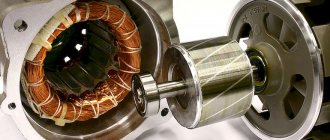
- Iph – current in the stator circuit, which manufacturers indicate on the nameplate or in the accompanying documentation;
- U – supply voltage.
In a simplified version, specialists take 6-7 µF for every 0.1 kW of power consumption. Under significant mechanical loads, the winding may burn out. A soft start of the electric motor is ensured by an additional capacitor. It performs its functions within 2-5 seconds. The capacity is chosen 2.5-3.5 more than the result of the previous calculation. The rated voltage is 50-70% higher than the operating parameters of the power supply network.
An asynchronous motor is connected to a single-phase source. In this option, it is necessary to create a phase shift to start rotating the rotor. Starting is provided by a separate winding. A special capacitor is installed in this circuit. For a simplified selection circuit, take 8-12 μF for every 0.1 kW of power consumption.
For your information. To prevent overheating and damage to parts, it is recommended to connect inductive loads of this type through capacitors designed for an operating voltage of at least 450 V.
Calculation of a quenching capacitor for connecting an LED strip can be done using the formula:
Where:
- I – current in the circuit;
- Up (Ud) – power supply voltage (drop across diodes), respectively.
Connecting an electric motor with your own hands
How to choose a capacitor for a single-phase motor is already clear. The selection of capacitors for a three-phase motor is considered. How to practically mount a circuit to start an engine, what is necessary for this?
The circuit consists of the following components:
- engine (up to 3 kW);
- capacitors: starting and running, which differ in capacity;
- 220 V PVS start button.
Why do you need a start button? For short-term connection of an electrolytic two-terminal network and starting the motor rotation. The circuit is assembled according to the diagram in the picture below. All connections are made using bolted clamps. Bare sections of wires are subject to mandatory insulation.
The use of starting and operating capacitors makes it possible to start motors in any circuit. The capacity of the two-terminal circuits should be sufficient to start rotation and stable operation under load. It is preferable to use new parts.
Is it possible to install a larger capacitor?
The exact answer to the question raised in this section can be given after studying a specific diagram. If you need to select a part for a filter (oscillatory circuit), similar parameters are required. Otherwise, the frequency characteristics will not correspond to the design intent.
When smoothing out ripples in the power supply, such an upgrade instead of a standard product can be effective. In some cases, to limit the current in the circuit, you will have to select a suitable resistor. Through it it will be possible to discharge the capacitor without damage. The final decision is made taking into account the factors discussed above. Operating conditions, thermal and mechanical loads are essential. A reasonable increase in costs at the stage of purchasing reliable components will extend the service life of a functional device.
A little about security
It is no secret that replacing low-voltage capacitors can only be harmful to health if the polarity connection is incorrect. The first time you turn it on, the capacitor will explode. The second danger that can be expected from capacitors is the voltage between its plates. If you've ever taken apart computer power supplies, you've probably noticed the huge 200V electrolytes. It is in these capacitors that dangerous high voltages remain that can seriously injure you. Before replacing the capacitors of the power supply, we recommend completely discharging it either with a resistor or a 220V neon lamp.
Helpful advice: such capacitors do not like to be discharged through a short circuit, so do not short-circuit their terminals with a screwdriver to discharge them.
Starting and running capacitors are used to start and operate electric motors operating in a single-phase 220 V network.
That's why they are also called phase shifters.
Installation location: between the power line and the starting winding of the electric motor.
Symbol for capacitors in diagrams
The graphic designation on the diagram is shown in the figure, the letter designation is C and the serial number according to the diagram.
Divisions of capacitors with the possibility of changing the capacitance
According to this parameter, parts in this category are divided into:
Specific names determine the main design features and intended purpose. A typical permanent capacitor is created from conductive plates, rolled into a roll to reduce size. A dielectric is installed between them. The assembly is placed in a metal case or filled with polymer to provide the necessary security parameters.
In variable and tuning models, sets of mechanically driven plates are used. By changing the position of the working elements, the required capacity value is established. Each product is designed for a specific range of operating parameters. Such capacitors are used to fine-tune the oscillatory circuit. They are installed in radio-electronic units to regulate individual operating parameters during operation.
Capacity size: working and starting
The specific capacity of these elements can be calculated using an online calculator on the Internet. The calculation is done independently using formulas.
For the trigger element
There are two known formulas for determining the capacity of a starting two-terminal network:
- for the “star” circuit – Cп = 2800*I/U;
- for the “triangle” circuit – Cп = 4800*I/U.
The rated current is calculated using the expression:
Here:
- P – motor power;
- U – network voltage;
- η – efficiency;
- cosϕ – power factor.
For work item
You can select a working capacitor based on the following calculation:
A running and stable engine requires the use of a working tank to rotate under load.
Properties and parameters of capacitors
The main parameter of devices in this category is capacity (C). It determines the storage properties of the product. The operating principle is based on the transfer of electrons to the corresponding plate when a power source is connected. Depending on the polarity, positive (negative) charges appear on the corresponding electrode.
The size of the capacity depends on several parameters:
- plate sizes (plating area);
- distances between them;
- dielectric properties of the material in the gap.
For your information. Capacity is indicated in multiple units. Example: pF or pF is picofarad (10-12 farads).
The voltage of a flat capacitor is calculated using the formula:
Where:
- q – charge;
- e – dielectric constant;
- S – working area.
From this expression it is easy to conclude about the mutual influence of electrical and structural parameters. Capacity is determined as follows:
Where:
- d – distance between plates;
- U – voltage.
For convenience, a specific indicator is used:
where V is the volume of the product.
Based on it, a conclusion is drawn about how effectively the capacitor performs its main functions. With a high specific capacity, discharging takes longer if a similar load is connected.
The accuracy class or percentage deviation indicates the tolerance from the nominal capacity (values are indicated ± in%):
Consumer parameters of a dielectric are characterized by electrical strength. As a rule, the voltage rating in long-term operating mode for certain conditions is indicated on the product body, taking into account the ranges:
- temperature;
- relative humidity;
- pressure.
Detailed documentation indicates the breakdown voltage.
Inductance (self) changes the field strength of the capacitor. This reactive component “helps” the product discharge faster or slower compared to the design speed of the process. Such parasitic influences distort the operating characteristics of the oscillatory circuit. They must be taken into account when designing frequency-dependent circuits.
Losses are estimated by the electrical resistance of the insulating layers. If you connect the multimeter accordingly, you can clarify the actual leakage current. This parameter is measured over a certain period of time. It should be remembered that resistance depends on temperature and humidity.
For your information. Mica capacitors will discharge more slowly than paper capacitors under equal conditions, since the leakage currents differ by an order of magnitude.
For a comprehensive comparison of different parts in this category, stability is checked. This indicator characterizes the constancy of operating parameters. As a rule, the influence of temperature is taken into account. The specialized coefficient (TKE) shows the corresponding changes with an increase (decrease) of 1°C.
How to discharge a capacitor to minimize residual voltage? The answer to this question will help to obtain the study of absorption processes in the dielectric layer. The corresponding parameters are characterized by a correction factor (Ka). It increases with increasing temperature.
How to determine the optimal capacity size
This will require several capacitors connected in parallel. Along the connections, an ammeter measures the current consumed by the electric motor. It will decrease as the total capacity increases. But from a certain value its current will begin to increase. The minimum value of the current corresponds to the optimal value of the capacitance of the working capacitor. For normal operation of the engine, two capacitors are used with the possibility of parallel connection with each other. The connection diagram containing the starting and running capacitor is shown below.
Circuit diagrams of engines with starting and running capacitors
When starting, they are connected, forming the best capacity for accelerating the engine. Why use a separate starting capacitor of the same capacity if the installation turns out to be unreasonably cumbersome. Therefore, it is advantageous to use a container made up of two parts. Although it also includes a run capacitor, it becomes part of the starting virtual capacitor at startup. And those that can be switched off are called starting capacitors.
Calculation of working capacity
Experimental determination of the capacitance of capacitors is the most accurate. However, these experiments take a lot of time and are quite labor-intensive. Therefore, in practice, estimation methods are mainly used. They will require the engine power value and coefficients. They correspond to the “star” (12.73) and “triangle” (24) schemes. The power value is necessary to calculate the current strength. To do this, its nameplate value is divided by 220 (the value of the current mains voltage). Power is taken in watts.
The resulting number is multiplied by the corresponding coefficient and gives the value of microfarads.
Selection of starting capacity
But the mentioned method determines the capacity of the working capacitor. If the engine is used in an electric drive, it may not start with it. An additional starting capacitor will be required. In order not to bother yourself with selection, you can start with a container of the same size. If the motor still does not start due to the load on the drive side, capacitors must be added in parallel to start the electric motor.
After each connected instance, you need to apply voltage to the engine to check startup. After the engine starts, the last of the connected capacitors will complete the formation of the capacitance required for the engine in starting mode. If for any reason, after being connected to the electrical network, the capacitor is disconnected from it, it must be discharged.
To do this, use a resistor with a value of several kilo-ohms. First, before connecting, its leads must be bent so that their ends are at the same distance as the terminals. The resistor is taken by one of the terminals with pliers with insulated handles. By pressing the resistor leads to the terminals for a few seconds, the capacitor is discharged. After this, it is advisable to check with a multimeter-voltmeter how many volts there are on it. It is desirable that the voltage either resets to zero or remains less than 36 V.
Abbreviations
The standard version includes permanent (K) and trimmer (CT) capacitors. Variables (CV) are created according to individual orders. Below are individual parameters according to GOST 13 453-68.
Dielectric material:
- B – paper;
- MP – metal/film combination;
- C – mica;
- E – electrolyte;
- K – ceramics.
According to the degree of protection from external influences, a hermetic (G) version and a pressurized housing (O) are distinguished.
Design:
- M – monolith;
- B – barrel;
- D – disk;
- C – sectional option.
Operating mode (current):
- I – pulse;
- U – universal (pulse, constant and variable);
- H – only constant;
- P – variable/constant.
Other features:
- U – capacitor designed to operate in the VHF range;
- M – compact dimensions;
- T – preservation of technical parameters is ensured when the temperature rises;
- B – the product is suitable for installation in high voltage networks.
The standard designation indicates (by position number):
- type of capacitor (K, CT or KP);
- code for dielectric and basic parameters (K10 ceramics for voltage up to 1600 V);
- current operating mode;
- production series or other technological designation.
Additional information:
- You can select products by combined (numeric and alphabetic) color marking;
- Abbreviations are applied to the compact body (instead of 1000uF - 1000m);
- The accuracy class is indicated in Latin font (U is ±);
- The rated voltage (Q-160V) is encoded in the same way.
Characteristics
The voltage created on the plates of a two-terminal network is equal to the potential difference:
Knowing the voltage and charge, you can calculate the capacitance (C). This is one of the main characteristics of a two-terminal network:
Where:
- C – capacitance, F (farad);
- q – charge accumulated by a two-terminal network, C (coulomb);
- U – voltage, V.
Electrical capacity is a physical quantity that is determined by dividing the plate charge by the potential difference between the plates. The unit of measurement for C is farad (F).
For your information. A capacitance equal to 1 F is a large value, so in practice it is measured: in microfarads (μF), picofarads (pF), nanofarads (nF).
Other parameters of the two-terminal network include:
- energy density;
- Rated voltage;
- polarity.
How to choose a capacitor
To better understand the algorithm for the correct actions, you can study the process of selecting a capacitor when connecting an electric motor to different power sources. If a three-phase network is used, the capacitance formula is suitable:
Where:
- k – fixed coefficient equal to 2,800/4,800 for the “star”/“triangle” circuit, respectively;
- Iph – current in the stator circuit, which manufacturers indicate on the nameplate or in the accompanying documentation;
- U – supply voltage.
In a simplified version, specialists take 6-7 µF for every 0.1 kW of power consumption. Under significant mechanical loads, the winding may burn out. A soft start of the electric motor is ensured by an additional capacitor. It performs its functions within 2-5 seconds. The capacity is chosen 2.5-3.5 more than the result of the previous calculation. The rated voltage is 50-70% higher than the operating parameters of the power supply network.
An asynchronous motor is connected to a single-phase source. In this option, it is necessary to create a phase shift to start rotating the rotor. Starting is provided by a separate winding. A special capacitor is installed in this circuit. For a simplified selection circuit, take 8-12 μF for every 0.1 kW of power consumption.
For your information. To prevent overheating and damage to parts, it is recommended to connect inductive loads of this type through capacitors designed for an operating voltage of at least 450 V.
Calculation of a quenching capacitor for connecting an LED strip can be done using the formula:
Where:
- I – current in the circuit;
- Up (Ud) – power supply voltage (drop across diodes), respectively.
Specifics of circuits with capacitors
When selecting the types of switching on of electric machines using starting and working two-terminal circuits for a 220 volt network, the following are distinguished:
- inclusion in the “triangle”;
- star connection.
For your information. What are the differences between starting and working two-terminal networks? “Starting” are elements that are used only for starting, and “working” are those that are constantly used in operation.
There is no need to use capacitive elements when connecting a 3-phase motor to a 380 volt network.
Schemes for connecting to a single-phase network
When installing a single-phase motor in a single-phase line, it is started using an additional winding. Such a motor has three outputs:
- from the working coil;
- from additional;
- common output for both windings.
When there is no marking, the coils are “ringed” by a tester to determine the correct connection.
Assembly type "Triangle"
To connect an asynchronous three-phase machine to a single-phase line, it is possible to use a delta connection. The starting capacitance is turned on according to the diagram.
Assembly type "Star"
The principle of assembling the starting circuit of a 3-phase motor, the windings of which are connected by a star, is similar. When it is possible to independently make such a connection of the windings, it is carried out on the terminal block.
Is it possible to install a larger capacitor?
The exact answer to the question raised in this section can be given after studying a specific diagram. If you need to select a part for a filter (oscillatory circuit), similar parameters are required. Otherwise, the frequency characteristics will not correspond to the design intent.
When smoothing out ripples in the power supply, such an upgrade instead of a standard product can be effective. In some cases, to limit the current in the circuit, you will have to select a suitable resistor. Through it it will be possible to discharge the capacitor without damage. The final decision is made taking into account the factors discussed above. Operating conditions, thermal and mechanical loads are essential. A reasonable increase in costs at the stage of purchasing reliable components will extend the service life of a functional device.
Checking the starting and running capacitors
You can check the capacitor using a capacitor capacitance meter; such devices are produced both separately and as part of a multimeter, a universal device that can measure many parameters. Let's consider checking with a multimeter.
- de-energize the air conditioner
- discharge the capacitor by short-circuiting its terminals
- remove one of the terminals (any)
- We set the device to measure the capacitance of capacitors
- We lean the probes against the terminals of the capacitor
- read the capacity value from the screen
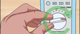
All devices have different designations for the capacitor measurement mode; the main types are shown below in the pictures.
In this multimeter, the mode is selected by a switch; it must be set to Fcx mode. The probes must be inserted into the sockets marked Cx.
Switching the capacitance measurement limit is manual. Maximum value 100 µF.
This measuring device has an automatic mode, you just need to select it, as shown in the picture.
The Mastech measuring tweezers also automatically measure capacitance, you just need to select the mode with the FUNC button, pressing it until the F indication appears.
To check the capacitance, we read its value on the capacitor body and set a deliberately larger measurement limit on the device. (If it's not automatic)
For example, the nominal value is 2.5 μF (μF), on the device we set 20 μF (μF).
After connecting the probes to the terminals of the capacitor, we wait for the readings on the screen, for example, the time to measure a capacitance of 40 μF with the first device is less than one second, with the second one more than one minute, so you should wait.
If the rating does not correspond to that indicated on the capacitor body, then it must be replaced and, if necessary, an analogue must be selected.