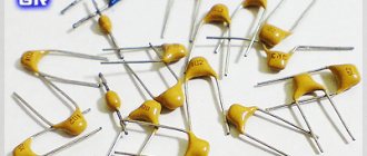
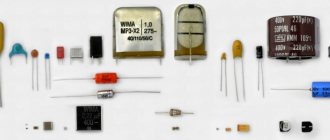
Many novice radio amateurs are faced with the problem of determining the characteristics of storage devices such as SMD capacitors. Small in size and used in surface mount technologies, these components on many printed circuit boards are labeled differently than their larger through-hole mount counterparts. This article will discuss the main types of radio component data, their designation and its interpretation.
SMD capacitor
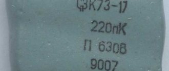
Marking capacitors using a numerical-alphabetic code.
The marking of capacitors may indicate the following parameters: Type of capacitor, its rated capacity, permissible deviation of capacitance, Temperature Coefficient of Capacitance (TKE), rated operating voltage.
The order of marking may be different - the first line may be the rated voltage, TKE or the manufacturer's brand name.
TKE may be absent altogether, the rated voltage is also not always indicated! There is almost always a marking of the nominal capacity. As for capacity, there are various ways to encode it symbolically. 1. Marking of the container using three numbers. With this marking, the first two digits indicate the capacitance value in picofarads, and the last one indicates the bit depth, i.e., the number of zeros that must be added to the first two digits. But if the last digit is “9”, division by 10 occurs. Code
| Capacitance(pF) | Capacitance(nF) | Capacitance(uF) | |
| 109 | 1.0(pF) | 0.001(nF) | 0.000001(uF) |
| 159 | 1.5(pF) | 0.0015(nF) | 0.0000015(uF) |
| 229 | 2.2(pF) | 0.0022(nF) | 0.0000022(uF) |
| 339 | 3.3(pF) | 0.0033(nF) | 0.0000033(uF) |
| 479 | 4.7(pF) | 0.0047(nF) | 0.0000047(uF) |
| 689 | 6.8(pF) | 0.0068(nF) | 0.0000068(uF) |
| 100 | 10(pF) | 0.01(nF) | 0.00001(uF) |
| 150 | 15(pF) | 0.015(nF) | 0.000015(uF) |
| 220 | 22(pF) | 0.022(nF) | 0.000022(uF) |
| 330 | 33(pF) | 0.033(nF) | 0.000033(uF) |
| 470 | 47(pF) | 0.047(nF) | 0.000047(uF) |
| 680 | 68(pF) | 0.068(nF) | 0.000068(uF) |
| 101 | 100(pF) | 0.1(nF) | 0.0001(uF) |
| 151 | 150(pF) | 0.15(nF) | 0.00015(uF) |
| 221 | 220(pF) | 0.22(nF) | 0.00022(uF) |
| 331 | 330(pF) | 0.33(nF) | 0.00033(uF) |
| 471 | 470(pF) | 0.47(nF) | 0.00047(uF) |
| 681 | 680(pF) | 0.68(nF) | 0.00068(uF) |
| 102 | 1000(pF) | 1(nF) | 0.001(uF) |
| 152 | 1500(pF) | 1.5(nF) | 0.0015(uF) |
| 222 | 2200(pF) | 2.2(nF) | 0.0022(uF) |
| 332 | 3300(pF) | 3.3(nF) | 0.0033(uF) |
| 472 | 4700(pF) | 4.7(nF) | 0.0047(uF) |
| 682 | 6800(pF) | 6.8(nF) | 0.0068(uF) |
| 103 | 10000(pF) | 10(nF) | 0.01(uF) |
| 153 | 15000(pF) | 15(nF) | 0.015(uF) |
| 223 | 22000(pF) | 22(nF) | 0.022(uF) |
| 333 | 33000(pF) | 33(nF) | 0.033(uF) |
| 473 | 47000(pF) | 47(nF) | 0.047(uF) |
| 683 | 68000(pF) | 68(nF) | 0.068(uF) |
| 104 | 100000(pF) | 100(nF) | 0.1(uF) |
| 154 | 150000(pF) | 150(nF) | 0.15(uF) |
| 224 | 220000(pF) | 220(nF) | 0.22(uF) |
| 334 | 330000(pF) | 330(nF) | 0.33(uF) |
| 474 | 470000(pF) | 470(nF) | 0.47(uF) |
| 684 | 680000(pF) | 680(nF) | 0.68(uF) |
| 105 | 1000000(pF) | 1000(nF) | 1.0(uF) |
2. The second option - marking is done not in pico, but in microfarads, and the letter µ is placed instead of the decimal point.
| Code | Capacitance(uF) |
| µ1 | 0,1 |
| µ47 | 0,47 |
| 1 | 1,0 |
| 4µ7 | 4,7 |
| 10µ | 10,0 |
| 100µ | 100,0 |
3. Third option.
| Code | Capacitance(uF) |
| p10 | 0.1pF |
| IP5 | 0.47pF |
| 332p | 332pF |
| 1HO or 1no | 1nF |
| 15H or 15no | 15.0nF |
| 33H2 or 33n2 | 33.2nF |
| 590H or 590n | 590nF |
| m15 | 0.15uF |
| 1m5 | 1.5uF |
| 33m2 | 33.2uF |
| 330m | 330uF |
| 10m | 10.0uF |
Soviet capacitors used “p” instead of the Latin “r”.
The permissible deviation of the nominal capacity is marked with a letter, often the letter follows the code defining the capacity (the same line).
| Letter designation | Tolerance(%) |
| B | ± 0,1 |
| C | ± 0,25 |
| D | ± 0,5 |
| F | ± 1 |
| G | ± 2 |
| J | ± 5 |
| K | ± 10 |
| M | ± 20 |
| N | ± 30 |
| Q | -10…+30 |
| T | -10…+50 |
| Y | -10…+100 |
| S | -20…+50 |
| Z | -20…+80 |
Further, there may be (or may not be!) marking of the Temperature Coefficient of Capacity (TKE). For capacitors with non-standardized TKE, coding is done using letters.
| Tolerance at -60²…+85²(%) designation | Letter code |
| ± 10 | B |
| ± 20 | Z |
| ± 30 | D |
| ± 50 | X |
| ± 70 | E |
| ± 90 | F |
Capacitors with a linear dependence on temperature.
| TKE(ppm/²C) | Letter code |
| 100(+130….-49) | A |
| 33 | N |
| 0(+30….-47) | C |
| -33(+30….-80) | H |
| -75(+30….-80) | L |
| -150(+30….-105) | P |
| -220(+30….-120) | R |
| -330(+60….-180) | S |
| -470(+60….-210) | T |
| -750(+120….-330) | U |
| -500(-250….-670) | V |
| -2200 | K |
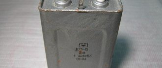
Next comes the voltage in volts, most often in the form of a regular number. For example, the capacitor in this picture is marked with two lines. The first (104J) means that its capacitance is 0.1 μF (104), the permissible deviation of the capacitance does not exceed ± 5% (J). The second (100V) is the voltage in volts.
In addition, the voltage of the capacitors can also be encoded using letters (see table below).
| Voltage (V) | Letter code |
| 1 | I |
| 1,6 | R |
| 3,2 | A |
| 4 | C |
| 6,3 | B |
| 10 | D |
| 16 | E |
| 20 | F |
| 25 | G |
| 32 | H |
| 40 | C |
| 50 | J |
| 63 | K |
| 80 | L |
| 100 | N |
| 125 | P |
| 160 | Q |
| 200 | Z |
| 250 | W |
| 315 | X |
| 400 | Y |
| 450 | U |
| 500 | V |
How to determine the rating and voltage
Many manufacturers do not indicate on their products such basic characteristics for any capacitor as operating voltage and rating (nominal capacity).
The rating of these electronic components is determined in the following ways:
- Using a measuring instrument such as a multimeter that has the function of measuring the nominal value. To measure the nominal value, the control probes of the device are connected to special connectors. Then the switch is set to the largest measurement limit (in most multimeters this is 200 µF). After this, the probes are applied to the contacts of the capacitor; after a few seconds, the value of the storage device’s rating is shown on the device’s display.
Marking SMD capacitors.
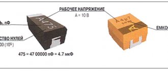
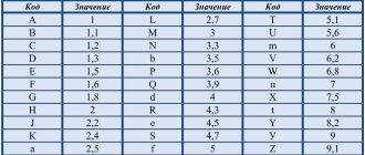
The dimensions of SMD capacitors are small, so their marking is done very succinctly. The operating voltage is often coded by letter (2nd and 3rd options in the figure below) in accordance with the data provided in the previous section. The nominal capacity can be encoded either using a three-digit digital code (option 2 in the figure) or using a two-digit alphanumeric code (option 1 in the figure). When using the latter, you can still find two (and not one letter) with one number on the case (option 3 in the figure).
The first letter can be either a manufacturer's code (which is not always interesting) or indicate the rated operating voltage (more useful information), the second can be an encoded value in picoFarads (mantissa). The number is an exponent (indicates how many zeros need to be added to the mantissa). For example, EA3 may mean that the rated voltage of the capacitor is 16V(E) and the capacitance is 1.0 * 1000 = 1 nanofarad, BF5, respectively, the voltage is 6.3V(V), the capacitance is 1.6 * 100000 = 0.1 microfarad and. etc.
| Letter | Mantissa. |
| A | 1,0 |
| B | 1,1 |
| C | 1,2 |
| D | 1,3 |
| E | 1,5 |
| F | 1,6 |
| G | 1,8 |
| H | 2,0 |
| J | 2,2 |
| K | 2,4 |
| L | 2,7 |
| M | 3,0 |
| N | 3,3 |
| P | 3,6 |
| Q | 3,9 |
| R | 4,3 |
| S | 4,7 |
| T | 5,1 |
| U | 5,6 |
| V | 6,2 |
| W | 6,8 |
| X | 7,5 |
| Y | 8,2 |
| Z | 9,1 |
| a | 2,5 |
| b | 3,5 |
| d | 4,0 |
| e | 4,5 |
| f | 5,0 |
| m | 6,0 |
| n | 7,0 |
| t | 8,0 |
How to determine the rating and voltage
Many manufacturers do not indicate on their products such basic characteristics for any capacitor as operating voltage and rating (nominal capacity).
The rating of these electronic components is determined in the following ways:
- Using a measuring instrument such as a multimeter that has the function of measuring the nominal value. To measure the nominal value, the control probes of the device are connected to special connectors. Then the switch is set to the largest measurement limit (in most multimeters this is 200 µF). After this, the probes are applied to the contacts of the capacitor; after a few seconds, the value of the storage device’s rating is shown on the device’s display.
Important! Before measuring the capacitance, the SMD drive must be discharged - the charge remaining in the plates can damage the electronic circuits of the multimeter.
- Using a specialized RLC measuring device.
In order to find out the operating voltage of SMD device, use the following simple method:
- Using a multimeter, measure the voltage between the terminals of the component included in the circuit;
- The resulting value is multiplied by 1.5.
The operating voltage calculated in this way will be approximate; a more accurate value of this characteristic can be found from the marking code of the capacitor or its description.
Color coding of ceramic capacitors.
Colored stripes are applied on the capacitor body, from left to right, or from top to bottom.
As a rule, the capacity value is encoded by the first three stripes. Each color in the first two stripes has its own number: black - number 0; brown - 1; red - 2; orange - 3; yellow - 4; green - 5; blue - 6; purple - 7; gray - 8; white - 9. Thus, if, for example, the first stripe is brown and the second is yellow, then this corresponds to the number -14. But this number will not be the value of the nominal capacitance of the capacitor; it still needs to be multiplied by the multiplier encoded by the third stripe.
In the third stripe, the colors have the following meanings: orange - 1000; yellow - 10000; green - 100000. Let's assume that the color of the third strip of our capacitor is yellow. We multiply 14 by 10000, we get the capacity in picofarads -140000, otherwise, 140 nanofarads or 0.14 microfarads. The fourth strip indicates permissible deviations from the nominal capacity (accuracy), as a percentage: white - ± 10%; black - ± 20%. The fifth bar is the rated operating voltage. Red color - 250 Volts, yellow - 400.
How to determine the rating and voltage
Each miniature capacitor is characterized by two main parameters: the nominal capacity and the maximum voltage at which it can still operate. Let us consider the procedure for identifying each of these indicators in more detail.
Nominal value
To determine the first of the parameters, you can use the following methods:
- Try to measure their nominal capacity using a device (multimeter) that has the appropriate function;
- Use a special RLC meter for these purposes.
Note! Both of these methods involve removing the capacitor from the board or soldering at least one pad.
The procedure for measuring SMD capacitors with both devices can be found in the instructions for their use.
Operating voltage
In order to demonstrate the situation with the maximum operating voltage of a given element, there is only one reliable way. It consists of trying to measure the voltage between the contacts where an unknown capacitor is sealed (with the equipment turned on, of course).
After determining this indicator, we can assume that the capacitor itself is designed for a voltage approximately one and a half times higher than the value obtained after the measurement.
Color coding of electrolytic capacitors.
As for small-sized electrolytic capacitors, their nominal capacity is coded using two stripes and one color spot.
The first and second bars determine the number, and the spot determines the multiplier. The color coding of the first two stripes of electrolytic capacitors fully corresponds to the marking of ceramic capacitors. It is only necessary to take into account that the capacitance value of “electrolytes” is obtained in microfarads, and not picofarads as with ceramic capacitors. The color of the spot indicating the multiplier: black - 1; brown - 10; red - 100; gray - 0.01; white - 0.1; For example, the color of the first stripe is blue (number 6), the second is orange (number 3), and the color of the spot is brown (multiplier - 10). This means 63*10= 630 microfarads. If an electrolytic capacitor has a third stripe, then it determines its rated voltage: white color - 3 volts; yellow - 6.3 volts; black - 10 volts; green - 16 volts; blue - 20 volts; gray - 25 volts; pink - 35 volts.
The positive terminal in such electrolytic capacitors is thicker than the negative terminal.
The use of any materials from this page is permitted provided there is a link to the “Electrical is Easy” website.
Designation in diagrams
In general, when repairing and re-soldering modern SMD printed circuit boards, it is most convenient when you still have a diagram at hand, looking at which it is much easier to understand what is installed, to find out the location of a certain part, because an SMD capacitor in appearance may not differ at all from the same transistor. The designations of these parts in the circuits remained the same as they were before the arrival of chips on the market, and therefore the capacity and other necessary characteristics can also be easily found by a radio amateur who has not encountered SMD components.