Capacitor Polarity
Polarity: Some capacitors are made in such a way that they can only withstand the applied voltage of one polarity and not the other. This is due to their design: the dielectric is a microscopically thin layer of insulation applied to one of the plates during manufacture using a constant voltage. These are called electrolytic capacitors and their polarity is clearly marked.
Figure 1 – Capacitor polarity
Reversing the polarity of the voltage across an electrolytic capacitor can destroy this ultra-thin dielectric layer, resulting in the destruction of the device. However, the thickness of this dielectric allows extremely high capacitance values to be obtained with a relatively small package size. For the same reason, electrolytic capacitors tend to have low voltage ratings compared to other types of capacitor designs.
Application of reverse polarity voltage
Aluminum electrolytic capacitors are usually manufactured for a specific, fixed polarity of the voltage applied to them and cannot operate normally when the polarity is reversed. Applying the voltage in reverse polarity means that the oxide film on the cathode foil must act as a dielectric instead of the film on the anode foil. Considering that the oxide film on the cathode foil is much thinner, in the reverse voltage polarity mode it is capable of functioning as a dielectric only up to a few volts (1–3 V). At reverse voltages with values greater than those indicated, the electrochemical reaction of oxidation of the cathode foil begins. The occurrence of such a reaction means that:
- all available circuit current flows through this capacitor (it loses blocking ability);
- depending on the magnitude of the flowing current, an abnormally large amount of heat is generated within a fairly short time;
- Hydrogen is released on the original anode foil.
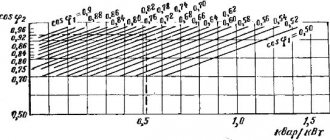
Depending on the magnitude of the current and the length of time that reverse polarity voltage is applied to the aluminum electrolytic capacitor, the safety valve may operate, and in particularly severe cases, excessive heat generation can cause the capacitor to catch fire. However, a reverse polarity voltage within 1–3 V is adequate to the blocking abilities of the oxide layer on the cathode foil. Accordingly, it usually does not cause any problems. The graph on the right side of Fig. Figure 2 shows that the reverse current flowing through an aluminum electrolytic capacitor does not change significantly until the reverse voltage exceeds 3 V.
Rice. 2. Operation of an aluminum electrolytic capacitor when a voltage of reverse polarity is applied
Capacitor equivalent circuit
Equivalent Circuit: Since the plates in a capacitor have some resistance, and since no dielectric is a perfect insulator, there is no such thing as a "perfect" capacitor. In real life, a capacitor has both series resistance and parallel resistance (leakage resistance), interacting with its purely capacitive characteristics:
Figure 2 – Capacitor equivalent circuit
Fortunately, it is relatively easy to make capacitors with very low series resistance and very high leakage resistance!
Physical dimensions of the capacitor
For most electronics applications, minimal size is the goal for component design. The smaller the components can be made, the larger the circuitry that can be built into a smaller package, which typically also reduces weight. In the case of capacitors, there are two main limiting factors for the minimum device size: operating voltage and capacitance . And these two factors tend to contradict each other. For any particular dielectric material chosen, the only way to increase the capacitor's voltage rating is to increase the thickness of the dielectric. However, as we have seen, this leads to a decrease in capacity. Capacitance can be restored by increasing the wafer area, but this makes the component larger. This is why you can't judge a capacitor's capacitance in farads simply by size. A capacitor of any given size may be relatively high in capacitance and low in operating voltage, or vice versa, or have some compromise between these two extremes. Let's look at the following two photographs as an example:
Figure 3 – High voltage oil capacitor
This is a fairly large capacitor in physical size, but it has a fairly low capacitance value: only 2 µF. However, its operating voltage is quite high: 2000 volts! If this capacitor were redesigned to have a thinner layer of dielectric between its plates, at least a hundredfold increase in capacitance could be achieved, but at the cost of significantly reducing its operating voltage. Compare the photo above with the one below. The capacitor shown in the bottom picture is an electrolytic component similar in size to the one above, but with very different capacitance and operating voltage values:
Figure 4 – Electrolytic capacitor
The thinner dielectric layer gives it a much higher capacitance (20,000 µF) and dramatically reduces the operating voltage (35 VDC, 45 V peak).
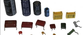
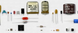
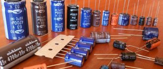
Here are some examples of different types of capacitors, all smaller in size than those shown previously:
Figure 5 – Ceramic capacitors
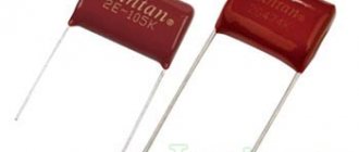
Figure 6 – Film capacitors
Figure 7 – Electrolytic capacitors
Figure 8 – Tantalum capacitors
Electrolytic and tantalum capacitors are polarized (polarity sensitive) and are always labeled as such. For electrolytic capacitors, the negative (-) terminals are marked with arrows on the body. Some polarized capacitors have polarity marked on the positive terminal. The large 20,000 uF electrolytic capacitor shown above has the positive (+) terminal marked with a plus sign. Ceramic, mylar, film, and air capacitors do not have polarity markings because these types are non-polar (they are not polarity sensitive).
Capacitors are very common components in electronic circuits. Take a close look at the following photo - each component labeled "C" on the PCB is a capacitor:
Figure 9 – Capacitors on the network card
Some of the capacitors on the board are standard electrolytic capacitors: C30 (top of board, center) and C36 (left side, 1/3 of top). Some others are a special type of electrolytic capacitor called tantalum because this is the type of metal used to make the plates. Tantalum capacitors have a relatively high capacitance for their physical size. On the board shown above, the tantalum capacitors are C14 (just below left of C30), C19 (directly below R10, which is below C30), C24 (lower left corner of the board), and C22 (lower right).
Examples of even smaller capacitors can be seen in this photo:
Figure 10 – Capacitors on the hard drive
The capacitors on this PCB are "surface mount devices" for space reasons, as are all resistors. According to component labeling convention, capacitors can be identified by labels beginning with the letter "C".
Original article:
- Practical Considerations - Capacitors
Overvoltage. Part 1: Long-term exposure to overvoltage
As the voltage applied to an aluminum electrolytic capacitor increases, its internal parts are exposed to increasing electric field strength. If the field strength is high enough, electrical charge transfer through the dielectric layer can occur. This single discharge can increase like an avalanche, causing a so-called partial discharge of the capacitor. This phenomenon is known as "sparking" due to its characteristic sonic appearance. If these partial discharges - at a voltage level typical for a given application of an aluminum electrolytic capacitor - occur too frequently or are of sufficiently large magnitude, they will result in complete breakdown of the dielectric and catastrophic failure of the component. The term "catastrophic failure" refers to a condition of a capacitor where physical signs of damage to its internal parts can be seen.
Definition of test procedure
Due to the delicate nature of partial discharges in the initial region of their occurrence, a unique detector was designed to detect and study this phenomenon. It captures "subtle" microvolt-level capacitor voltage sags (sparking below the audible detection threshold) with a time resolution corresponding to single or slightly avalanche-amplified partial discharges. It also captures the small voltage fluctuations across a capacitor with a time resolution on the order of nanoseconds that characterize the avalanche flashovers that occur. This is shown schematically in Fig. 3.
Rice. 3. Operating principle of the “spark” detector
Discharges can occur on the terminals of an aluminum electrolytic capacitor, current leads, anode and cathode foils and its aluminum body, provided that they are all wetted with electrolyte. Due to a number of theoretical premises and practical considerations, it was decided to select down conductors for a detailed study of the manifestation of partial discharges in aluminum electrolytic capacitors. The current leads were placed in a thermostated vessel with electrolyte and polarized (molded) at a constant current density of 333 μA/cm2.