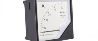
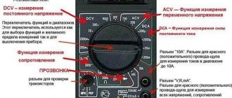
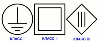
Ammeters are used to measure the strength of direct or alternating electric current. The graphic designation of this device on electrical diagrams is a circle with the letter “A” placed inside. This measuring device determines the strength of electric current in amperes, milliamps or microamps. An ammeter is connected in series to the open circuit.
Application of ammeters:
Ammeters are used in industry, telecommunications, laboratory research and other fields of activity to measure direct or alternating electric current in the range from units of μA to tens of kA. In this case, the value of the measured current should not exceed the maximum scale value of the device, taking into account the connection diagram. Depending on the measurement limit, modern ammeters are divided into:
- microammeters;
- milliammeters;
- ammeters;
- kiloammeters.
How are devices classified according to their operating principle?
Section 1. State system for ensuring the uniformity of measurements
Topic 1.1. General information about electrical measurements
Title of laboratory work No. 1
Characteristics of electrical measuring instruments and their classification.
Explanation of symbols on the scales of electrical measuring instruments
Learning objective:
— consolidate theoretical knowledge on the topic “General information about electrical measurements”
— acquire practical skills in deciphering the symbols on the scales of electrical measuring instruments
Educational results declared in the third generation Federal State Educational Standards:
— use control, testing and measuring equipment;
— basic concepts of measurements, methods and instruments of electrical measurements.
Laboratory tasks:
- Review learned material
- Decipher the symbols on the scales of measuring instruments.
- Prepare a laboratory report
Class provision (learning tools):
— Educational and methodological literature:
1. Panfilov V.A. Electrical measurements. - M.: Academy, 2012.
2. Malinovsky V.N. Electrical measurements. - Moscow: Energoizdat, 2012.
— Technical training aids:
a set of measuring instruments of various systems and accuracy classes.
Instructions for performing laboratory work
1. Answer questions to reinforce the theoretical material you have learned.
2. Having received three measuring instruments from the teacher, decipher the symbols on the instrument scale (use table 1), enter the data in table 2.
3. Describe the operating principle of various electrical measuring mechanisms, enter the data in Table 3.
4. Answer questions to reinforce theoretical material for laboratory work
5. Prepare a report on the work.
Questions to consolidate the theoretical material studied
Where are electrical measuring instruments used?
1. To control the parameters of technological processes.
2. To control the parameters of spacecraft.
3. For experimental research in physics, chemistry, biology, etc.
4. In all previously listed areas.
How are devices classified according to their operating principle?
1. Voltmeters, ammeters, wattmeters, counters, ohmmeters, frequency meters.
2. Devices of magnetoelectric, electromagnetic, electrodynamic and other systems.
3. Devices are not classified according to their operating principle.
Electromechanical instruments are used to measure voltage, current, power and other electrical quantities in low-frequency direct and alternating current circuits. The name of an electrical measuring instrument is determined by its purpose. There are voltmeters, ammeters, wattmeters, ohmmeters, phase meters and combined instruments - ampere-voltmeters, volt-ohmmeters and others.
According to the principle of operation, electromechanical devices are divided into devices of magnetoelectric, electrodynamic, ferrodynamic, electromagnetic, electrostatic, induction and some other systems that are used less frequently. Whether a device belongs to a particular system is indicated by a symbol on its scale.
For any measurements, it is important that the devices have as little influence as possible on the operating mode of the electrical circuits in which the measurements are made.
Pointer electrical measuring instruments are the most commonly used. Much less often, the purpose of the pointer in the device is performed by a light spot (“bunny”). Often, to improve the accuracy of scale reading, a mirror strip along the entire scale is placed under the pointer arrow. This allows you to avoid parallax errors (counting is done when the arrow and its image in the mirror are aligned).
The instrument scale can be divided into different numbers of divisions. In this case, they talk about the price of a scale division. To calculate the division price, you can use the formula:
, i.e. the ratio of the upper limit of the measured value on a given scale to the number of scale divisions. Any electrical measuring device is also characterized by sensitivity, that is, the ratio of the movement of the pointer (in linear or angular units, or in the number of scale divisions) to the measurement of the value of the measured quantity that caused this movement. The sensitivity of the device is numerically equal to the reciprocal of the scale division value.
The metrological properties of a device characterize its accuracy class. It is indicated by a number on the instrument scale and indicates the reduced error limit of the instrument, expressed as a percentage. The State Standard (GOST) establishes eight accuracy classes: 0.05; 0.1; 0.2; 0.5; 1.0; 1.5; 2.5; and 4.0. The accuracy class is numerically equal to the maximum error when the instrument needle deflects to the full scale.
Electrical measuring instruments must be selected based on the specified value of the relative error. If the measured quantity must be determined with precision
2%, then instruments with an accuracy class of 1.5 and higher, but not 2.5 and lower, can be used for measurements
What types of ammeters are there?
Depending on the type, ammeters are divided into measuring devices:
- direct current;
- alternating current.
The following types of ammeters exist:
- magnetoelectric - used to measure small quantities of direct electric current;
- electromagnetic - provide measurement of alternating (frequency 50 Hz) and direct current;
- electrodynamic - measure alternating (frequency up to 200 Hz) and direct current;
- thermoelectric - designed to measure the value of high-frequency alternating electric current;
- ferrodynamic - are self-recording instruments and are used in automatic measurement systems.
Depending on the type of scale used, these devices are:
- switches;
- electronic (digital).
Types of electrical measuring instruments
Classification of electrical measuring instruments:
- variable;
- permanent;
- combined devices.
By level of accuracy:
Each number indicates a percentage of the permissible error.
According to the essence of the work:
- electromagnetic;
- induction;
- magnetoelectric;
- ferromagnetic.
When carrying out measurement tests, it is necessary to select the appropriate measuring device correctly.
- Ammeters are devices for measuring current values. The unit of measurement is Ampere (A).
- Voltmeter – measures the voltage of the electrical network. The unit of measurement is Volt (V).
- An ohmmeter is an auxiliary device that measures resistance in an electrical circuit. Measured in Ohms (Ohm).
- A wattmeter is an element that measures network power. The unit measured is Watt (W).
- Frequency meter – a frequency meter for alternating pulse values. Measured in Hertz (Hz).
Operating principle of an ammeter
The operation of different types of ammeters is based on different operating principles. The methods used to measure electric current mainly depend on the application of the device.
The principle of operation of a magnetoelectric ammeter is based on the fact that a constant magnetic field and electric current flowing through the windings of the frame cause the occurrence of torque. The flow of electric current through the device causes the needle to move. The latter is directly connected to the frame. Therefore, the angle of rotation of the arrow is directly proportional to the amplitude of the measured electric current.
The design of an electrodynamic ammeter includes a fixed and moving coil. To measure currents of small magnitude, they are connected in series, and for large currents - in parallel. The needle is attached to the moving coil and moves as a result of the interaction between the currents flowing in the fixed and moving coil.
The design of a thermoelectric ammeter is based on a magnetoelectric device with a contact or non-contact transducer. The latter is a conductor with a thermocouple welded to it. Passing through the converter, the electric current causes it to heat up, which is detected by a thermocouple. The resulting thermal radiation affects the magnetoelectric device. Its frame deviates by an angle proportional to the value of the flowing electric current.
The operation of a digital ammeter is based on analog-to-digital conversion of the amplitude of the measured current. Passing through an analog-to-digital converter (ADC), the signal is quantized by time and then by level. The received information is converted into digital form and displayed on the display.
How to choose
When choosing electrical measuring instruments, you must remember that for official research, quality control, warranty service, and testing of safety devices, only models that are included in the State Register of Measuring Instruments can be used.
It also makes sense to choose “smart” electrical measuring instruments, the advantage of which is that with their help you can not only collect, but also analyze measurements. Such devices have the greatest performance and functionality.
How to calculate a shunt for an ammeter?
In cases where it is necessary to measure electric current exceeding the maximum value of the ammeter scale, it is necessary to use a shunt. Its resistance is calculated using the following formula:
Rsh=(Ra*Ia)/(Ish-Ia)
Wherein:
- Rsh is the required shunt resistance (in Ohms);
- Ra – internal resistance of the ammeter (in Ohms);
- Ia is the maximum current value measured by an ammeter (in Amperes);
- Ish is the approximate value of the measured current (in Amperes).
Accuracy class of electrical measuring devices
In addition to other characteristics, the accuracy class, which reflects the features of the device, is also important. Accuracy depends on the permissible margin of error that may arise as a result of the design features of the specific equipment. According to GOST, the following accuracy classes are distinguished: 4.0 and 0.05; 0.1 and 0.2, as well as 0.5 and 1.0, 1.5 and 2.5. The class does not exceed the relative error of the device, determined by the formula: - ɣ = ∆x / xpr * 100%. In this case, ɣ is the reduced error, ∆x is the absolute error, and xpr is the measured parameter.
Ammeter internal resistance
For correct operation, the value of the internal resistance of the ammeter must be an order of magnitude less than the value of the circuit resistance. In some cases, such information is not available. Then you should measure the internal resistance of the ammeter used. To do this, a load resistor and an ammeter are connected in series to the power source, and a sensitive voltmeter is connected in parallel to the latter. After switching on the circuit, instrument readings are taken. The value of the internal resistance of an ammeter is determined as the ratio of the readings of a sensitive voltmeter and an ammeter.
Voltage measurement.
A device designed to measure voltage is called a voltmeter , and, unlike an ammeter, it is connected to the circuit parallel to the section of the circuit at which the voltage needs to be determined. And, again, in contrast to an ideal ammeter, which has zero resistance, the resistance of an ideal voltmeter should be equal to infinity. Let's figure out what this is connected with:
If there were no voltmeter in the circuit, the current through the resistors would be the same and determined by Ohm’s Law as follows:
So, the current value would be 1 A, and accordingly the voltage on resistor 2 would be equal to 20 V. This is all clear, but now we want to measure this voltage with a voltmeter and turn it on in parallel with
. If the resistance of the voltmeter were infinitely large, then no current would simply flow through it (), and the device would not have any effect on the original circuit. But since it has a finite value and is not equal to infinity, a current will flow through the voltmeter and, in connection with this, the voltage across the resistor will no longer be the same as it would be in the absence of a measuring device. That is why the ideal voltmeter would be one through which no current would pass.
As with the ammeter, there is a special method that allows you to increase the voltage measurement limits of the voltmeter. To do this, it is necessary to connect an additional resistance in series with the device, the value of which is determined by the formula:
This will cause the voltmeter to be n times less than the measured voltage. As usual, let's look at a small practical example
Here we have added additional resistance to the circuit. Our task is to measure the voltage across the resistor: . Let's determine what will appear on the voltmeter screen when turned on in this way:
Ammeter. Current measurement video
Drivers of cars and trucks are interested in how to connect an ammeter and voltmeter in a car. The need to install these indicators is explained by the desire to have full control over the condition of the battery and generator set. Most modern cars and previously produced ones do not have such indicators installed by the manufacturer. True, in cars with on-board computers, it is possible to control the voltage in the car’s circuits; in other models, the owners install the devices.
How to connect an ammeter and voltmeter in a car
It is especially interesting for owners of used cars, since many components and assemblies, including the generator set, are already quite worn out, so they may not work properly. The warning lamp only signals the absence of on-board voltage, and this is clearly not enough. For example, if you do not notice the increased charging voltage of the battery in time, this can lead to its failure.
About the functions performed by these pointers
An ammeter installed in an electrical circuit will indicate the electrical current consumed by the system. Using these data, you can judge the battery charging process and promptly identify and eliminate problems that arise. The voltmeter also allows you to keep this process under the control of the driver, which increases the service life of electrical equipment. Here are the main reasons for installing these devices on a car.
What products are used?
measuring instruments
Today such a problem does not exist, since there is a large selection of such products in retail chains. You can install an electronic clock in the panel, which simultaneously shows the voltage of the on-board network along with the current time. There are electronic tachometers, which, after pressing the desired button, perform the functions of a voltmeter. Such devices do not cause any particular problems for owners.
Also today, automobile ammeters and voltmeters are available for sale, and individual drivers independently adjust the devices that are used in radio-electronic devices. Installing such indicators is fraught with some difficulties, since it is necessary to select shunts for them, calibrate or manufacture new scales. Therefore, we will not dwell on this.
How to install such indicators?
Let's assume that you managed to purchase an ammeter or voltmeter intended for use in cars; now let's look at the process of installing them. It is worth recalling the features of connecting them to electrical circuits.
The ammeter is connected only in series between the current source and the consumers, and the polarity of the connection must be observed, plus from the source to the plus of the device, and so on. The voltmeter is connected only in parallel to the power source, also subject to polarity.
Connecting the ammeter
After installing the wires, check that the connections are correct. To do this, turn on the load, for example, low or high beam. The ammeter should show a discharge; if it shows the opposite value, then the connection wires should be swapped. Next, you should start the engine and make sure that the battery is charging.
Classification according to other criteria:
by purpose - measuring instruments, measures, measuring transducers, measuring installations and systems, auxiliary devices;
by the method of presenting measurement results - showing and recording (in the form of a graph on paper or film, printout, or in electronic form);
by measurement method - direct assessment devices and comparison devices;
by method of application and design - panel-mounted (attached to a panel or panel), portable and stationary;
according to the operating principle:
electromechanical:
magnetoelectric; electromagnetic; electrodynamic; electrostatic;
ferrodynamic; induction; magnetodynamic; electronic; thermoelectric;
electrochemical.
Thermoelectric ammeters and voltmeters
A thermoelectric ammeter is a combination of a magnetoelectric measuring mechanism with a thermal converter (Fig. 7-14), and a voltmeter, in addition, has an additional resistance.
The two welded ends of two wires made of different metals are called a thermocouple. The unwelded ends of the thermocouple are called free ends, and the welded ends are called working ends.
When the working ends of the thermocouple are heated, a potential difference will appear at the free ends, called thermoelectromotive force - thermo-emf. Thermo-e. d.s. depends on the metals forming the thermocouple and the temperature difference between the working and free ends of the thermocouple, and at a constant temperature of the free ends - on the temperature of the working end of the thermocouple. By welding a heater conductor to the working end of the thermocouple, we obtain a thermal converter.
Rice. 7-14.
Thermoelectric ammeter.
When alternating current passes through the heater, it heats up, heats the working end of the thermocouple, and thermo-e appears at its free ends. d.s. If a measuring mechanism is connected to these ends, then a current will appear in it and the moving part will rotate at an angle depending on both the thermo-e. d.s., and from the measured alternating current passing through the heater. The effective current values are indicated on the ammeter scale.
A voltmeter differs from an ammeter by an additional resistance connected in series with the thermal converter heater. In this case, the angle of rotation of the moving part depends not only on the current, but also on the voltage at the voltmeter terminals. The effective value of this voltage is indicated on the scale.
The accuracy of thermoelectric devices corresponds to classes 1.5–2.5.
Thermoelectric devices are used in alternating current circuits of high and high frequencies (up to 10-50 MHz).
Types of electrical measuring instruments
Classification of electrical measuring instruments:
- variable;
- permanent;
- combined devices.
By level of accuracy:
Each number indicates a percentage of the permissible error.
According to the essence of the work:
- electromagnetic;
- induction;
- magnetoelectric;
- ferromagnetic.
When carrying out measurement tests, it is necessary to select the appropriate measuring device correctly.
- Ammeters are devices for measuring current values. The unit of measurement is Ampere (A).
- Voltmeter – measures the voltage of the electrical network. The unit of measurement is Volt (V).
- An ohmmeter is an auxiliary device that measures resistance in an electrical circuit. Measured in Ohms (Ohm).
- A wattmeter is an element that measures network power. The unit measured is Watt (W).
- Frequency meter – a frequency meter for alternating pulse values. Measured in Hertz (Hz).


