Types and types of voltmeters
All voltmeters can be divided according to: principle of operation, purpose, method of application and design.
Based on the principle of operation, devices are divided into groups:
- Electromechanical voltmeters.
- Electronic voltmeters.
Let's look at each group specifically.
Electromechanical and electronic voltmeters
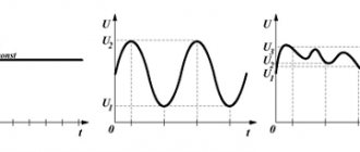
These measuring instruments are direct conversion devices. The measured value in them is converted directly into readings on the scale of the reading device. It is intended for visual assessment of the measured voltage.
The scale looks like a sequence of marks with numbers and forms a fixed part of the device. The distance between two adjacent marks is the scale division value. Scales can be linear and nonlinear, one-sided (o is located at the beginning) and two-sided (o is located in the middle). A number is usually written on the scale indicating the accuracy class of the device.
The moving part of the device consists of a frame located between the poles of a permanent magnet. Current flows through the frame winding. An arrow is associated with the movable frame, by the magnitude of the deflection angle of which you can use a scale to estimate the value of the measured parameter. This angle directly depends on the current flowing through the frame winding, and therefore on the voltage value that is measured.
Such devices use the magnetoelectric method . It is most often used in electromechanical instruments to measure various physical quantities.
It should be noted that such devices are rarely used separately. As a rule, they are an integral part of devices with more complex circuit design.
In addition to the magnetoelectric measurement method, others are used in electromechanical devices: electromagnetic, electrodynamic, ferrodynamic, thermoelectric, and rectification method.
Based on the requirements for voltage meters, the use of these devices is more preferable than electromechanical ones. And these requirements are as follows: reducing the methodological measurement error.
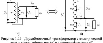
To measure voltages at various points in the circuit, a voltmeter is connected in parallel to the circuit being measured . Therefore, its use should not distort the real picture. It should not bypass a section of the circuit; therefore, its input resistance should be large (ideally, it should tend to infinity).
Electronic voltmeters can be divided into two groups. One is made up of analog devices, the other is digital. The difference between them lies in the form of providing information about the measurement results.
Possible analogues
The input voltage, the value of which needs to be measured, is supplied to the scaling device. It is made in the form of a high-precision multi-limit resistor divider. The number of resistors corresponds to the number of voltage measurement ranges.
How does a voltmeter work?
There are two types of voltmeters: analog, which indicate the value by tilting the needle of a mechanical device, and the increasingly used digital ones, equipped with complex electronic circuits.
Analog voltmeters are usually ammeters with a resistor RV in series with a very large electrical resistance value. That is, in essence, they measure the current IV flowing through it, and the scale shows the value, which is the result of the calculation: UV = IV * RV .
Digital instruments, as a rule, have the opposite design (that is, they are voltmeters, not ammeters). This is because making a digital voltage meter is relatively simple. If we connect it in parallel with a low resistance resistor, we get an ammeter. The indicator value can be calculated using the equation: UV = IV * RV .
There is, however, a type of analog voltmeter that does not operate on the same principle as an ammeter. This is an electrostatic voltmeter. In practice, this is a capacitor with one fixed plate and another movable one. The electrical interaction of the plates causes the movement of the pointer attached to the moving part. Using such a voltmeter, you can measure even very high electrical voltages, and the value of its internal resistance is almost infinite.
Main characteristics of devices
The greater the internal resistance of the voltmeter, the less its influence on the measured circuit. Therefore, devices with higher input impedance have greater accuracy when making measurements.
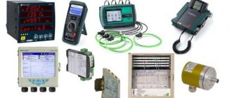
In order to evaluate the capabilities of the device, its advantages over others, and make a final conclusion about the possibility of purchasing it, you must carefully familiarize yourself with its technical parameters, which include:
- internal resistance of the voltmeter;
- range of voltages measured by a voltmeter;
- AC voltage frequency range;
- measurement error of the device.
The range must be taken into account based on what voltage values will have to be dealt with. Most voltmeters can measure voltages from several tens of millivolts to hundreds of volts . This range is quite acceptable for many users. The exceptions are extended range millivoltmeters and kilovoltmeters.
The error shows the possible deviation of the measured value from the reference value. Determined at the stage of factory testing of the device. Expressed as a percentage or fraction of a percent.
All these parameters are presented in the description for a specific device.
Built-in miniature digital voltmeters from China: review and application details
To monitor the operation of equipment, constantly operating instruments are useful - voltmeters, ammeters, etc. Constant monitoring of parameters will help the user understand whether everything is in order with the equipment, or “something went wrong.” This review will present two miniature digital voltmeters: 30 Volt and 100 Volt. They are similar, but not the same.
Voltmeters are designed to measure direct voltage of positive polarity.
Design of digital voltmeters
Both voltmeters are frameless; and due to the very small size of the board with electronics, at first it may seem that they consist only of indicators:
This photo immediately shows the difference between a 100 V voltmeter (left) and a 30 V voltmeter (right): a 100 V voltmeter has a 3-wire connection, and a 30 V voltmeter has a two-wire connection.
Why is this done?
Everything is very simple: voltmeters use a linear stabilizer with a maximum input voltage of 30 V. Therefore, the “junior” voltmeter can be powered directly from the measured voltage, and the “senior” voltmeter, when used to measure voltages above 30 V, requires a separate source for its power supply.
If a 100-volt voltmeter is used to measure voltages up to 30 V, then you can short the red and yellow wires together and also power them from the measured voltage.
But, as usual, there is a nuance. If you power the device from the measured voltage, then it should be no lower than what is needed to power the voltage stabilizer in the device, and this is 5 V (recommended by the seller). That is, in this case, the measured voltage must be at least 5 V (tests have shown operability at 4 V, but this is not guaranteed for the entire temperature range; and no one has canceled the spread of parameters of the elements on the voltmeter board).
The voltmeters were purchased on Aliexpress HERE, the price (at the date of review) was ridiculous: from $0.76 for a 30-volt device and up to $1.35 for a 100-volt device.
A few words about the dimensions of voltmeters.
If we talk about the dimensions briefly, the dimensions of the devices are 30.2 x 11 x 8.6 mm.
Broken down by detail, the dimensions will be as follows: board length - 30.2 mm, board width - 11 mm, display block length - 22.6 mm, display block width - 10.4 mm, display block height (from the board level) - 6.2 mm, height of the entire device ( from the bottom of the board to the top of the indicator) - 8.6 mm.
The height of the numbers on the indicator is 7.1 mm (0.28 inches).
Let's look at the reverse side of voltmeters, i.e. on boards with electronics:
The voltmeter boards are absolutely identical, and differ only in the location of two elements (these locations are indicated by arrows in the photo).
That is, if you wish and have “direct hands,” you can transform one of them into another and vice versa. But there is no economic sense in this; it is better to immediately buy whichever one you need (or, if in doubt, both at once).
The purpose of the wires is obvious: black is ground, red is power (it is also the measured voltage for a 30-volt device), yellow is the measured voltage.
There are very few parts on the voltmeter boards.
The basis of voltmeters is an analog-to-digital microcontroller, alas, without markings. However, there were no complaints about his work.
The microcontroller performs analog-to-digital signal conversion; then, probably, some simple computational processing (perhaps averaging several measurements); and then sends the result to the 3-digit LED indicator.
The microcontroller is powered by stabilizers marked “7533-1 E1125D” and “6513 TA502H”.
Both stabilizers produce an output voltage of 3.3 V, and are most likely clones of the popular AMS1117 stabilizers.
There is a trim resistor for calibrating voltmeters.
That's all, actually.
Testing digital voltmeters
I must immediately say the main thing: the tests tested the accuracy of the settings of the voltmeters in the form in which they came from China. There is no point in checking the accuracy simply “as such,” since the instruments have calibration adjustments that allow you to adjust the settings of the voltmeters if the reading error turns out to be high.
The test program is as follows: first we check the accuracy of a 100-volt voltmeter, and then the synchronism of the voltmeter readings when measuring the same voltage.
We will also check the current consumption of the devices and the input resistance for a 100-volt device.
So, let's go.
Checking the accuracy of the factory setting , voltage - 5 Volts:
Everything is fine, the error is less than 1%.
Voltage - 12 V:
Here, formally, there is no error at all, but this means, most likely, that both devices are mistaken.
Please note: after 10 Volts on the tested voltmeter, the decimal point jumped by 1 digit, and now the device does not show hundredths of a Volt.
Let's move on.
Voltage - 30.1 V:
Likewise, there seems to be no error.
Next I would need to check at a voltage of 100 V, but I didn’t have such a power supply. The maximum that was found was voltage - 49.4 V:
A small error of 0.1 V was found here.
A 100 V voltmeter allows you to measure voltages lower than its supply voltage. But the accuracy will drop for a trivial reason: due to too much “weight” of the error per unit of the least significant digit.
You can measure, for example, the voltage on the battery:
Now let’s check the coincidence (or discrepancy) of the voltmeter readings with each other for two voltages (4 V and 30 V):
The agreement between the voltmeter readings turned out to be very good.
Now - an example of the practical application of one of these voltmeters.
I attached a low-grade voltmeter (30 V) to a QC trigger, designed to receive voltages of 9 and 12 Volts from power banks and QC chargers (review of a QC trigger with a power bank).
This trigger sends a command to the connected device to output 9 or 12 V, but does not check its execution.
Now there is a check:
In this photo, another feature of the wills on the indicator turned out to be clearly visible; it glows brighter than other numbers.
Probably, the voltmeter supplies each of the 3 digits of the indicator with the same current, and for illumination it bypasses them one by one; As a result, the smaller the number of active segments in a digital number, the brighter they glow.
This cannot be called a significant problem, but attention should be paid to it.
Now - about current consumption by voltmeters .
A 30 V voltmeter (with a red indicator) consumes 11 mA, a 100 V voltmeter (with a yellow indicator) consumes noticeably more, almost 16 mA.
When the voltmeter was powered at 100 V from a source with a voltage of 30 V, the heating of the stabilizer on the device board was very noticeable (the result was 0.4 W of power dissipation on the stabilizer).
Hence the recommendation: power a 100-volt device with a voltage of no more than 20 V. The best option is with a voltage of 5 V, which is available almost everywhere.
The reason for the higher consumption of this voltmeter may lie in the higher consumption of its indicator (everything else is the same).
The input impedance of a 100-volt device is 100 kOhm.
There is no point in talking about the input resistance of a 30-volt device, since the input there is combined with the power supply.
The range for adjusting the accuracy of voltmeters using a trimming resistor on the board is about 8%.
Results, conclusions, subtleties of application
First, about the subtleties of application when measuring negative voltages .
If the voltage does not exceed 30 V, then everything is done simply: the ground of the voltmeter is connected to the minus of the power supply, and the plus of the voltmeter to the ground of the power supply. And everything works right away!
If the measured voltage exceeds 30 V, then everything becomes much more complicated.
In this case, it is possible to use only a 100-volt device; Moreover, to power it you will need a separate isolated source (in bourgeois terminology - floating or even flying).
This is a serious complication of the circuit, which is why it makes sense to think about other devices for similar measurements.
Theoretically, instead of an isolated power source, it is possible to extinguish the excess voltage with a resistor or zener diode; but such a solution is not beautiful and limits the range of operating voltages.
Now - about the advantages of the tested voltmeters .
The advantages are:
- low price;
- good measurement accuracy;
- Possibility of power supply with measured voltage;
- small dimensions and weight.
The advantages are very significant, but disadvantages :
- lack of brightness adjustment (in the dark the indicator glow feels too bright, and in bright light it feels dull);
- the presence of a strobe effect (when moving the eyes or the voltmeters themselves);
- do not measure alternating voltage;
- difficulties with measuring negative voltages above 30 V.
You can check the current price or buy tested voltmeters here, and there is a wide selection of indicator colors (in addition to those tested with yellow and red).
Thank you all for your attention!
Homemade devices
How to make a voltmeter with your own hands, what it is for, how it works, how a voltmeter is connected, how to use a voltmeter - this is an incomplete list of questions that beginner radio amateurs and ordinary users have. The principle of operation of a voltmeter or the principle of operation of a voltmeter was discussed earlier when considering its different types and types.
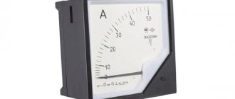
At very little cost you can make it yourself . Its main part is a dial gauge. The scale has a voltage designation - the Latin letter “V”. Of course, it is advisable to have a voltmeter with the required measuring range. On the left side of the scale there should be o, and on the right there should be a number that shows the maximum voltage value measured by this device.
Let's consider several voltmeters from different manufacturers
1. V3-57 - microvoltmeter
Measuring device model V3-57 - voltmeter-converter rms. indications. Designed for RMS measurements. voltage values of arbitrary shape and their linear transformation. in constant voltage current. The instrument scale is marked in rms. voltage values and decibels (from 0 dB to 0.775 V). It is used for monitoring and adjusting various radio-television devices and communications equipment, calculating the frequency characteristics of broadband devices, examining noise-resistant signals, etc.
Basic technical data:
— Voltage measurement limits 10 μV - 300 V with boundary zones: 0.03-0.1-0.3-1-3-10-30-100-300 mV 1-3-10-30-100-300 V
— Frequency limits 5 Hz - 5 MHz
— Permissible error, %: ±1 (30-300 mV), ±1.5 (1-10 mV), ±2.5 (0.1-0.3 mV and 1-300 V), ±4 (0 .03 mV)
— Input resistance 5 MOhm ±20%
— Input capacitance: 27pF (0.03-300 mV) and 12 pF (1-300 V)
— Voltage at the output of the linear converter. 1 V
— Resistance at the output of the linear converter. 1 kΩ ±10%
— Limit coefficient. signal amplitude 6*(Uk/Ux)
Some tips for beginners
These tips will help beginners who have to use a voltmeter in their work for the first time. There are few of them:
- Connecting a voltmeter.
- Maintain polarity.
The polarity of the connected voltmeter test leads must correspond to the polarity of the voltage indicated on the diagram.
The voltmeter should always be connected in parallel to the circuit being measured. This differs from an ammeter, which is connected to a gap. For a full-wave AC rectification circuit, the polarity of the test leads can be ignored. The probes must be held so that your hands touch only their isolated part.
Originally posted 2018-03-28 15:34:30.
Features of the scheme
The circuit of a digital voltmeter is based on discrete quantities. A simplified diagram includes the following elements:
- input device (ID);
- analog-to-digital converter (ADC);
- digital readout unit (DRB);
- control device (UD).
Interaction between the UE and the digital data center occurs through decimal numbers. In the case of determining AC voltage, the VU functions as a simple converting device, producing direct current. At this moment, the DSB is working on an analog signal, which is represented by a digital code.
Converting current from one type to another is also typical for devices such as multimeters. Some modern models of voltmeters use a binary code system, which greatly simplifies the process of receiving a signal.
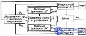
A simple circuit of a voltmeter-ammeter with a converter
A digital voltmeter-ammeter with a frequency converter necessarily includes a generator that monitors voltage changes in the electrical circuit. In this case, the measurement is carried out in stages at intervals. The generator in the electrical circuit is of the linear type. To compare the received data, the device has a trigger. In turn, to calculate the frequency, it is important to use a counter that receives a discrete signal. This happens at the output of the voltmeter-ammeter converter. In this case, the magnitude of the limiting voltage is taken into account.
The information goes directly to the input of the voltmeter-ammeter. At this stage, the comparison process is carried out, and when an impulse occurs, the system records the zero level. The signal in the voltmeter-ammeter directly goes to the trigger, and as a result, a positive voltage is obtained at the output. The pulse returns to its original position only after the device makes a comparison. In this case, any changes in the limiting frequency that have formed in a given period of time are taken into account. The conversion factor is also taken into account. It is calculated based on the signal strength indicator.
Additionally, the formula contains a counting pulse that appears at the output of the generator. As a result, voltage can only be displayed when there are certain fluctuations that occur in the electrical circuit. Ultimately, the signal must reach the trigger output and be counted there. In this case, the number of pulses is recorded in a voltmeter-ammeter. As a result, an indicator is triggered, which notifies you of the presence of voltage.
Double integration voltmeters
The double integration digital DC voltmeter operates on the principle of periodic repetition. In this case, the return of the source code in the chain is carried out automatically. This system operates exclusively with direct current. In this case, the frequency is pre-rectified and supplied to the output device.
Sampling errors are not taken into account in voltmeters. Thus, moments of mismatch of counting pulses may occur. As a result, one parameter can be very different at the beginning and end of the interval. However, as a rule, the error is not critical due to the operation of the converter.
A particular problem is noise interference. As a result, it can significantly distort the voltage indicator. Ultimately, this is reflected in the magnitude of the pulse, namely its duration. Thus, these types are not very popular among digital voltmeters.
Measurement errors
The measurement error of a voltmeter is directly related to the power source. In this case, the pickup voltage at the output should be taken into account. Most often, general interference changes the resistance parameters. As a result, this figure may decrease significantly. Today, there are three proven ways to combat various types of interference in voltmeters. The first technique is to use shielded wires. In this case, it is very important to isolate the input of the electrical circuit from the equipment.
The second way is to have an integrating element. As a result, the interference period can be significantly reduced. Finally, the last trick is considered to be the installation of special filters on voltmeters. Their main task is to increase the resistance in the electrical circuit. As a result, the amplitude of the noise at the output after the block is significantly reduced. It should also be noted that many transducer systems can significantly increase measurement speed. However, as performance increases, the accuracy of data logging decreases. As a result, such converters can cause a lot of noise in the electrical circuit.
Digital voltmeter converters
Today, there are many different types of converters that are installed in voltmeters. The most common are time-pulse models. Additionally, there are pulse code converters.
Their distinctive feature from other devices is the ability to perform bit-by-bit balancing. At this time, pulse-frequency models are deprived of such a privilege. However, they can be used to perform spatial coding, which can be extremely important in some studies. This is especially true for voltage measurements in closed electrical circuits.