Content
To characterize the electric current in a circuit, we already have two physical quantities: current ($I$) and voltage ($U$).
We use an ammeter to measure current. This means that there is a device for measuring electrical voltage.
What is a device for measuring voltage called? It is called a voltmeter . In this lesson we will look at its application, the rules for connecting to an electrical circuit and its other characteristics.
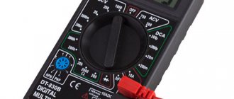
Digital multimeters.
The inclusion of a microprocessor and additional converters in the circuit of a digital voltmeter allows you to turn it into a universal measuring device - a multimeter. Digital multimeters measure AC and DC voltage, current, resistor values, electrical frequency, etc.
When creating digital automatic instruments for measuring resistance, inductance and capacitance, methods associated with converting the measured parameter into voltage or current, frequency or time interval, as well as methods based on bridge and compensation circuits, are widely used.
Fig.35. Simplified circuit of a digital automatic complex resistance meter with a microprocessor
The most widely used are digital automatic devices with a microprocessor, made according to circuits using balanced bridges. Balancing is carried out by automatic regulation of two bridge bodies (for each of the measured parameters). A simplified block diagram of a digital automatic complex resistance meter with a microprocessor is shown in Fig. 35
Figure 2.17 Digital voltmeter with microprocessor
When used together with an oscilloscope, multimeters are capable of measuring time intervals (period, pulse duration, etc.). The presence of a microprocessor in the electrical circuit of the voltmeter allows for automatic correction of measurement errors, auto-calibration and fault diagnostics.
In Fig. Figure 2.17 shows a digital voltmeter with a microprocessor as an example. The main devices of the voltmeter are: microprocessor, ADC, signal normalization and control units.
The signal normalization block, using appropriate converters, converts the input measured parameters (AC and DC voltage, DC resistance, etc.) to a unified signal, which is fed to the ADC input. The latter usually operates using the double integration method. The control unit provides selection of the operating mode for a given type of measurement, control of the ADC, display, and creates the desired configuration of the measurement system.
The basis of the control unit is a microprocessor, which is connected to other nodes through shift registers. The microprocessor is controlled using a keyboard located on the control panel or through a standard interface (interface unit; joint) of a connected communication channel. The operating program of the microprocessor is stored in the read-only memory device ROM and is provided using the random access memory device RAM.
For measurements, built-in highly stable and precision resistive reference voltage dividers, a differential remote control amplifier and a number of external elements (attenuator and mode selection device, reference voltage unit uop) are used. All pulse and digital devices are synchronized by clock generator signals.
Control questions:
1. What principle is implemented in pulse-code digital voltmeters?
2. On what principle are time-pulse voltmeters built?
3. Explain the operation of a microprocessor driven digital voltmeter.
4. Explain the working of double integration digital voltmeter.
Answers for the lazy
1. In pulse-code (with bit-by-bit balancing) digital voltmeters, the principle of the compensation method of measuring voltage is implemented. The measured voltage U'x received from the input device is compared with the compensating voltage UK generated by a precision divider and a reference voltage source. The compensation voltage has several levels, quantized in accordance with the binary-decimal number system.
2 The operating principle of a time-pulse (time-based) type voltmeter is based on the conversion of the measured voltage using an ADC into a proportional time interval, which is filled with counting pulses following at a known stable repetition rate. As a result of this transformation, the discrete signal of measuring information at the output of the converter has the form of a packet of counting pulses, the number of which is proportional to the level of the measured voltage.
3 The most widespread are digital automatic devices with a microprocessor, made according to circuits using balanced bridges. Balancing is carried out by automatic regulation of two bridge bodies (for each of the measured parameters).
4 The principle of operation of a voltmeter is similar to the principle of operation of a circuit with time-pulse conversion, with the difference that here, during the measurement cycle T, two time intervals T1 and T2 are formed. In the first interval, the measured voltage is integrated, and in the second, a certain reference voltage is integrated. The duration of the measurement cycle T = T1+ T2 is deliberately set to be a multiple of the period of interference acting at the input, which leads to an increase in the noise immunity of voltmeters.
Voltmeter
A voltmeter is a device for measuring voltage at the poles of a current source or at some other part of the circuit.
Voltmeters are very similar in appearance to ammeters. How to distinguish them then? If the ammeter scale shows the letter $A$, then the voltmeter scale will definitely have the letter $V$.
Voltmeters come in different types. It depends on their purpose. You will most often see either demonstration voltmeter (Figure 1, a) or a laboratory one (Figure 1, b).
As you can guess from the names of the devices, a demonstration voltmeter is used to demonstrate experiments, and you will use a laboratory voltmeter when performing laboratory work.
Figure 1. Types of voltmeters
On the scale of each voltmeter there is a higher (maximum) voltage value that it is capable of measuring. Exceeding this limit may result in device failure.
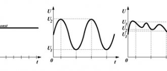
Operating principle of digital voltmeters
The operating principle of digital measuring instruments is based on discrete and digital representation of continuous measured physical quantities.
A simplified block diagram of a digital voltmeter (Fig. 2.12) consists of an input device, an ADC, a digital readout device and a control device. The input device contains a voltage divider; in AC voltmeters it also includes an AC-DC converter.
Figure 2.12 Simplified block diagram of a digital voltmeter
Block diagram of a digital voltmeter
An analog-to-digital converter converts an analog signal into a digital signal, represented by a digital code. The analog-to-digital conversion process is the essence of any digital device, including a voltmeter. The use of binary decimal code in digital voltmeter ADCs makes it easier to convert the code back to a decimal number, which is reflected by a digital readout device. A digital readout device records the measured value. The control device combines all components of the voltmeter.
Based on the type of ADC, digital voltmeters are divided into two main groups:
• pulse code (with bit-by-bit balancing);
• time-pulse.
The analog-to-digital converter of voltmeters converts the DC signal into a digital code, which is why digital voltmeters are also considered DC instruments. To measure alternating current voltage, a converter to direct voltage, most often an average rectified value, is placed at the input of the voltmeter.
Let's analyze the main technical characteristics of the average digital DC voltmeter:
• measurement range: 100 mV, 1 V, 10 V, 100 V, 1000 V;
• input impedance - high, usually more than 100 MOhm;
• sensitivity threshold (other names - quantum or discreteness unit) in the range of 100 mV can be 1 mV, 100 μV, 10 μV;
• number of characters (length of the digital scale) - the ratio of the maximum measured value in this range to the minimum; for example: a measurement range of 100 mV at a quantization level of 10 μV corresponds to (100-10-6)/(10 • 10-9) = 104 characters;
• noise immunity.
Accuracy of digital voltmeters. The distribution of error over the measurement range is determined by the limit of permissible relative, basic error , which characterizes the SI accuracy class:
(2.13)
where u is the measured voltage; Uк - final value of the range
measurements.
Performance. Modern ADC circuits used in digital voltmeters can provide very high speed, however, for reasons of accurate recording of the result obtained, in digital voltmeters it is reduced to approximately 20-50 measurements per 1 s.
Voltmeter in an electrical circuit
A voltmeter is connected to a certain section of the electrical circuit where the voltage needs to be measured.
Please note that if an ammeter connected in series to an electrical circuit will show the same current value in all sections of the circuit, then with a voltmeter we have a completely different story. It is designed to measure voltage on a specific section of the circuit.
To indicate electrical circuit diagrams, the voltmeter has its own symbol (Figure 2). It looks like a circle with the letter $V$ in the middle.
Figure 2. Symbol for indicating a voltmeter on an electrical circuit diagram
Time-pulse voltmeter with a linearly varying voltage generator.
The block diagram of a time-pulse digital voltmeter and timing diagrams explaining its operation are presented in Fig. 2.15, This type of voltmeter includes an ADC with intermediate conversion of the measured voltage into a proportional time interval. The ADC includes: linearly varying voltage generator GLIN; two comparison devices I and II; trigger T; AND logic circuit; counting pulse generator; pulse counter and digital readout device.
The discrete signal of measuring information at the output of the converter has the form of a packet of counting pulses, the number of which is Nproportional to the value of the input voltage U'x (i.e. Ux). The voltage UGLIN linearly varying with time from GLIN is supplied to the inputs I of both comparison devices. The other input of the comparison device I is connected to the housing.
At the moment of time when the voltage UGLIN = 0 at the input of the comparison device I, a pulse UUSI appears at its output, conditionally fixing the zero level of the input signal. This pulse, applied to the single input of the T trigger, causes a positive voltage to appear at its output. The trigger is returned to its original state by a pulse UусII coming from the output of comparison device II. The UycII pulse occurs at the moment of equality of the measured U'x and the linearly varying voltage UGLIN. A pulse UT generated at the output of the trigger with a duration of Δt = U'XS (here S is the conversion coefficient) is fed to the input of the AND circuit, the second input of which receives the signal UGSI from the generator of counting pulses, following with a frequency ƒ0 = 1/T0.
Figure 2.15 Digital voltmeter with pulse-time conversion: a - block diagram; b - timing diagrams.
At the output of the AND circuit, the Ucount signal appears only in the presence of UT and UGSI pulses at both of its inputs, i.e. counting pulses pass through the AND circuit when there is a signal at the trigger output. The number of counting pulses N ≈ ∆t/T0 passing through the circuit And is counted by the counter and displayed on the indicator of the digital reading device (DOC) of the device.
From the last two formulas we find the measured voltage:
U'x = N/(f0S), (2.14)
In this voltmeter, the value f0S is selected equal to 10m, where m = 1.2, 3,..., (the number m determines the position of the decimal point in the digital readout) so the device directly displays the value of the measured voltage.
The considered cycle of operation of a digital voltmeter is periodically repeated. In this case, the CLIN is returned to its original state and the circuit is prepared for the next measurement automatically. Digital AC voltmeters are built using the same principle. In these voltmeters, the alternating current voltage is pre-rectified and then supplied to the comparison device II.
Relation (2.14) does not take into account discreteness errors due to the discrepancy between the moment of appearance of counting pulses and the beginning and end of the interval At. However, an even greater error is introduced by the nonlinearity factor of the conversion coefficient S. A disadvantage of the pulse-time conversion method is also its low noise immunity. Noise interference superimposed on the measured voltage Ux changes it and, therefore, changes the moment of appearance of the pulse UсII, which determines the duration Δt of the counting time. Therefore, voltmeters built according to this scheme are the least accurate among digital ones.
The duration of Tx is directly proportional to the measured voltage and inversely proportional to the tangent of the voltage slope GLIN
Rules for connecting a voltmeter to an electrical circuit
- The voltmeter clamps must be connected to those points in the circuit between which the voltage must be measured. This connection is called parallel (Figure 3).
Figure 3. Parallel connection of a voltmeter to a circuit
You will learn more about the features of parallel connection
- One of the voltmeter terminals has a “ + ” sign. The wire connected to this terminal must be connected to the wire coming from the positive pole of the current source (Figure 4). If you connect the device incorrectly, the voltmeter needle will simply begin to deviate in the other direction.
Figure 4. Maintaining polarity when connecting a voltmeter to a circuit
Measuring voltage with a voltmeter in an electrical appliance
Using the above rules, let's try to measure voltage through practical experience.
Let's say it needs to be measured using an electric lamp. Let's assemble an electrical circuit consisting of a key, an electric lamp, and a current source. Let's connect in series to this circuit. We connect the voltmeter in parallel to the lamp terminals (Figure 5).
Figure 5. Measuring lamp voltage
The diagram of such an electrical circuit will look like this (Figure 6).
Figure 6. Electrical circuit diagram when measuring the voltage of an electric lamp
Please note that here we are using an ammeter to measure the current in an electric lamp. We measure its voltage with a voltmeter.
The ammeter is connected in series and the voltmeter in parallel.
What should be the strength of the current passing through the voltmeter compared to the current in the circuit? Does it differ from the current strength in the entire circuit?
Yes, it is different. The voltmeter is designed in such a way that the current passing through it is extremely small compared to the current in the electrical circuit itself. This eliminates voltage changes between the points to which the voltmeter is connected. This also helps to obtain more accurate voltage values.
2.4.2 Voltmeters with pulse-time conversion
The operating principle of a time-pulse (time) type voltmeter is based on the conversion of the measured voltage using an ADC into a proportional time interval, which is filled with counting pulses following at a known stable repetition rate. As a result of this transformation, the discrete signal of measuring information at the output of the converter has the form of a packet of counting pulses, the number of which is proportional to the level of the measured voltage.
Digital voltmeters with time-pulse conversion Voltmeters of this type use an ADC that performs “voltage - time interval - code” conversions. The principle of operation is to compare the measured signal with a reference linearly increasing voltage.
This type of CV measures the instantaneous voltage value. Pulse-time conversion voltmeters are simple and cheap, and have fairly high accuracy. Their main disadvantage is low noise immunity.
There are several circuit solutions used to create time-pulse voltmeters. Let's consider two such schemes.
Exercises
Exercise No. 1
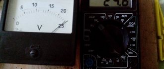
Consider the voltmeter scale (Figure 1, a).
Determine the division price. Draw its scale in a notebook and draw the position of the arrow at a voltage of $4.5 \space V$; $7.5 \space В$; $10.5 \space В$. Let us determine the division price of such a voltmeter. Let's take the values 0 and 3. From 0 to 3 we have only two divisions. It turns out that $\frac{3 \space B - 0 \space B}{2} = 1.5 \space B$. The division price of this voltmeter is $1.5 \space V$.
Figure 8 shows the readings of this voltmeter at: $U_1 = 4.5 \space V$ (Figure 8, a); $U_2 = 7.5 \space B$ (Figure 8, b); $U_3 = 10.5 \space В$ (Figure 8, c).
Figure 8. Various voltmeter readings
Exercise No. 2
Determine the scale division value of the voltmeter shown in Figure 5. What voltage does it show?
The voltmeter scale in Figure 5 is identical to the voltmeter scale in Figure 1, a. We have already determined its division price in the previous exercise. The division price of this voltmeter is $1.5 \space V$.
In Figure 5, the voltmeter shows a voltage value equal to $1.5 \space V$.
Time-pulse voltmeters with double integration.
The principle of operation of a voltmeter is similar to the principle of operation of a circuit with time-pulse conversion, with the difference that here, during the T measurement cycle, two time intervals T1 and T2 are formed. In the first interval, the measured voltage is integrated, and in the second, a certain reference voltage is integrated. The duration of the measurement cycle T = T1+ T2 is deliberately set to be a multiple of the period of interference acting at the input, which leads to an increase in the noise immunity of voltmeters.
In CV with double integration, the “voltage - time interval” conversion (in contrast to CV with pulse-to-pulse conversion) occurs using an integrator. An integrator is a functional block on an operational amplifier that provides communication between the input uin and output uout voltages in the form
Double integration voltmeters are the most popular type of digital voltmeters and multimeters. Their main advantages are simplicity, high noise immunity with sufficient accuracy.
The block diagram of a digital voltmeter with double integration and timing diagrams explaining its operation are presented in Fig. 2.16.
Figure 2.16 Double integration digital voltmeter:
a - block diagram; b - timing diagrams.
The circuit contains an input device, a two-position switch, an integrator, a reference voltage source, a comparison device, a T trigger, a counting pulse generator, a control device, an AND logic circuit, a pulse counter and a digital readout device.
At the beginning of the measurement cycle at t = t0, the control device of the circuit generates a calibrated pulse UIcontrol with duration T1 = T0K, where Ta is the repetition period of the counting pulses; K is the meter capacity. At the moment the edge of the UIcontrol pulse appears, the switch is moved to position 1, and a voltage U/x, proportional to the measured voltage Ux, is supplied to the integrator from the input device. Then, over the time interval T1 = t1 - t0, the voltage U/x (proportional to the measured Ux) is integrated, as a result of which the increasing voltage at the output t1 of the integrator will be: UИ = ∫Ux′dt. At the moment t = t1 control t0
the UIcontrol signal moves the switch to position 2 and a reference negative voltage UION is supplied to the integrator from the reference voltage source. At the same time, the control signal UIcontrol overturns the trigger.
Integration of voltage UION is faster, since it is installed in the circuit. Integration of the reference voltage continues until the output voltage of the integrator again becomes equal to zero (in this case T2 = t2-t1). Therefore, during the second time
interval, a falling voltage t2 is formed at the integrator output
In this case, the longer the duration of the integration interval t1 T2, the higher the amplitude of the measured voltage U'x.
At time t = t2, the voltage UI at the output of the integrator becomes zero and the comparison device (the second input of which is connected to the housing) outputs a signal to the trigger, returning it to its original state. At its output, a pulse Ut of duration T2 is generated, which is supplied to the input of the I circuit. The UGSI signal from the counting pulse generator is supplied to its other input. At the end of the UT pulse coming from the trigger, the measurement process stops.
The conversion of the measured time interval T2 into an equivalent number of pulses N is carried out in the same way as in the previous method - by filling the T2 interval with periodic pulses of the counting pulse generator and counting their number with a counter. On the counter, and therefore on the digital reading device, the number of pulses NUcount, proportional to the measured voltage, is recorded
Ux:
(2.15)
This expression leads to the following formulas:
(2.16)
From the last equalities we get
(2.17)
From the above relationships it is clear that the error of the measurement result depends only on the level of the reference voltage (and not on several, as in a pulse-code device). However, there is also a discreteness error here. The advantage of the device is its high noise immunity, since it is integrating. Based on double integration circuits, devices with a higher accuracy class are produced than devices with GLIN. Voltmeters of this type have a measurement error of 0.005...0.02%.
Digital voltmeters of the highest accuracy class are created in combination: the circuits combine the methods of bit-by-bit balancing and pulse-time integrating conversion.
Double integration voltmeter measures the average voltage value over time T1