A simple alternating voltage voltmeter with a frequency of 50 Hz is made in the form of a built-in module that can be used either separately or built into a finished device. The voltmeter is assembled on a PIC16F676 microcontroller and a 3-digit indicator and does not contain very many parts.
Main characteristics of the voltmeter:
• The shape of the measured voltage is sinusoidal • The maximum value of the measured voltage is 250 V; • Frequency of measured voltage - 40...60 Hz; • Discreteness of measurement result display – 1 V; • Voltmeter supply voltage - 7...15 V. • Average current consumption - 20 mA • Two design options: with and without power supply on board • Single-sided printed circuit board • Compact design • Display of measured values on a 3-digit LED indicator
↑ Schematic diagram of a voltmeter for measuring alternating voltage
Implemented direct measurement of alternating voltage with subsequent calculation of its value and output to the indicator.
The measured voltage is supplied to the input divider made on R3, R4, R5 and through the separating capacitor C4 is supplied to the ADC input of the microcontroller. Resistors R6 and R7 create a voltage of 2.5 volts (half the power) at the ADC input. Capacitor C5, of relatively small capacity, bypasses the ADC input and helps reduce measurement errors. The microcontroller organizes the operation of the indicator in dynamic mode based on interruptions from the timer.
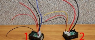
Voltmeter on Priora instead of a button
Another way to organically fit the device into the interior of the cabin is to put a voltmeter on the Priora instead of a button. On the instrument panel above the radio there is a plug that covers the space for placing an additional button.
To install a voltmeter instead of a button, you will need:
digital automotive voltmeter with a suitable display size;
- knife;
- needle file;
- hot glue;
- soldering iron;
- wires;
- solder;
- rosin.
Installing a voltmeter instead of a button is done as follows:
- remove the plug from the torpedo;
- cut a hole in the plug slightly smaller than the size of the voltmeter display;
- carefully adjust the size using a file;
- solder wires to the voltmeter;
- insert the voltmeter display into the hole in the button and fix it from the inside with hot glue;
- install the plug with the voltmeter in place.
After this, all that remains is to correctly connect the voltmeter to the vehicle’s on-board network.
↑ Design and details
the measured network 220 V. A simple 5 Volt power supply is provided, this part is circled with a pale green line in the diagram. Such a module is used when directly powered from the network being measured. In this mode, the lower limit of the measured voltage will be about 150 Volts.
Option with additional power supply + 7…15 V
. Measurement limits 0 – 250 Volts.
The voltmeter is assembled on a board made of one-sided foil fiberglass. The indicator is used with a common cathode. Resistors R6 and R7 can have a value of 47 - 100 kom. They must be selected with the same denominations or taken with a 1% tolerance. The linearity of the readings at the top of the scale depends on their equality of denominations. The value of resistors R8 – R12 is selected depending on the required brightness and light output of the indicator. In this case, it may be necessary to increase the capacitance of capacitor C1 to obtain a larger current value to power the indicator. When using an indicator with low light output, it is advisable to use a more powerful 7805 instead of the U1 (78L05) chip in order to avoid overheating.
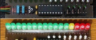
Multi-limit instrument
Anyone who has repeatedly encountered transistor designs and circuits knows that very often with a voltmeter it is necessary to measure circuits with voltages from tens of fractions of one volt to hundreds of volts. A simple homemade device with one resistor will not do this, so you will have to connect several elements with different resistances to the circuit. So that you understand what we are talking about, we suggest that you familiarize yourself with the diagram located below:
It shows that there are four resistors installed in the circuit, each of which is responsible for its own measurement range:
- From 0 volts to one.
- From 0 volts to 10V.
- From 0 V to 100 volts.
- From 0 to 1000 V.
The value of each resistor can be calculated based on Ohm's law. The following formula is used here:
R=(Uп/Iи)-Rп, where
- Rп is the resistance of the measuring unit, take, for example. 500 Ohm;
- Up is the maximum voltage of the measured limit;
- Ii is the current strength at which the needle deflects to the end of the scale, in our case - 0.0005 amperes.
↑ Program
The program is written in SI language (mikroC PRO for PIC) and provided with comments. The program uses direct measurement of alternating voltage
by a microcontroller, which simplifies the circuit and increases the accuracy of measuring small voltages. The microprocessor uses PIC16F676. The clock frequency of the internal oscillator is 4 MHz.
Program operation:
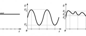
Over a certain period of time, multiple direct voltage measurements are made without reference to phase, and the minimum and maximum voltage values are determined. The difference between their values will be equal to the range of the measured voltage, which is displayed on the indicator.
↑ File in place...
And now about the modifications that are necessary to bring this “indicator” to fruition.
1. In order for it to start measuring voltage less than 3 Volts, you need to unsolder the jumper resistor R1 and apply a voltage of 5-12V from an external source to its right (according to the diagram) contact pad (higher is possible, but not advisable - the DA1 stabilizer gets very hot).
Apply the minus of the external source to the common wire of the circuit. Apply the measured voltage to the standard wire (which was originally soldered by the Chinese). 2. After modification according to paragraph 1, the range of the measured voltage increases to 99.9V (previously it was limited by the maximum input voltage of the DA1 stabilizer - 30V). The input divider ratio is about 33, which gives us a maximum of 3 volts at the DD1 input at 99.9V at the divider input. I supplied a maximum of 56V - I don’t have any more, nothing burned :-), but the error also increased.
3. If you recalculate the divider, then the “preadometer” can be used not only as a voltmeter - for example, you can display current, temperature, etc.
4. To move or completely turn off the point, you need to unsolder the R13 10 kOhm CHIP resistor, which is located next to the transistor, and instead solder a regular 10 kOhm 0.125 W resistor between the contact pad farthest from the trimming CHIP resistor and the corresponding control segment pin DD1 - 8, 9 or 10. Normally, the dot lights up on the middle digit and the base of the transistor VT1 is connected to the pin via a 10 kOhm CHIP. 9 DD1.
The current consumed by the voltmeter was about 15 mA and varied depending on the number of illuminated segments. After the described modification, all this current will be consumed from an external power source, without loading the measured circuit.
↑ Possible applications of a voltmeter
• Network voltage measurement (measurement limits 150 – 250 Volts)
• Measurement of regulated voltage taken from the LATR (measurement limits 0 – 250 Volts)
• Measuring voltage inside a device if there is an internal power source with a voltage of 8 - 15 Volts (measurement limits 0 - 250 Volts). A board version without a power supply is used. I used this option in a PWM AC voltage regulator.
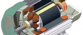
How to make a simple voltmeter with your own hands - diagrams and recommendations
Situations when a voltmeter should be at hand occur quite often. To do this, there is no need to use a complex factory device. Making a simple voltmeter with your own hands is not a problem, because it consists of two elements: a pointer measuring unit and a resistor. True, it should be noted that the suitability of a voltmeter is determined by its input resistance, which consists of the resistances of its elements.
But it is necessary to take into account the fact that there are different resistors with different values, and this means that the input resistance will depend on the installed resistor. That is, by choosing the right resistor, you can make a voltmeter to measure certain network voltage levels. The measuring device itself is more often evaluated by the indicator - relative input resistance per one volt of voltage, its unit of measurement is kOhm / V.
That is, it turns out that the input resistance in different measured areas is different, but the relative value is a constant indicator. In addition, the less the arrow of the measuring block deviates, the greater the relative value, and, therefore, the more accurate the measurements will be.
Measurement errors
The measurement error of a voltmeter is directly related to In this case, the pickup voltage at the output should be taken into account. Most often, general interference changes the resistance parameters. As a result, this figure may decrease significantly. Today, there are three proven ways to combat various types of interference in voltmeters. The first technique is to use shielded wires. In this case, it is very important to isolate the input of the electrical circuit from the equipment.
The second way is to have an integrating element. As a result, the interference period can be significantly reduced. Finally, the last trick is considered to be the installation of special filters on voltmeters. Their main task is to increase the resistance in the electrical circuit. As a result, the amplitude of the noise at the output after the block is significantly reduced. It should also be noted that many transducer systems can significantly increase measurement speed. However, as performance increases, the accuracy of data logging decreases. As a result, such converters can cause a lot of noise in the electrical circuit.
What types are there?
Devices of this kind are devices that perform direct readings when determining the voltage value. The main requirement for such devices is considered to be high internal resistance. When connected in parallel to the area where the voltage value needs to be tested, it should not have any effect on it.
If we classify devices that measure voltage, we can highlight the following points:
Devices are divided into two types: electromechanical and electronic. The first is a structure that includes an electromechanical mechanism and a device that displays the result. The latter are divided into analog and digital devices.
Attention! The name “electromechanical” means that all these structures: electromagnetic, magnetoelectric and others, produce a deflection of the electrical measuring system under the influence of electricity.
Analog devices include an amplifier in addition to a set of shunts. This is a unit that allows you to increase the lower measurement interval and increase Rin, as well as measure DC and AC voltage.
A digital voltmeter displays data in digital format. The circuit allows the voltage to be converted into an electrical code using an analog-to-digital device.
Testers by purpose allow you to perform the following options:
The structure, structure and methods of use allow the use of voltmeters for stationary placement, panel placement and for measurements in the field (portable).
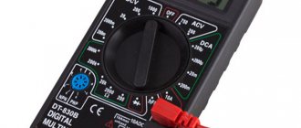
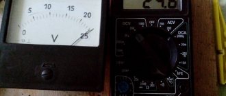
How to connect a voltammeter to a charger - a selection of diagrams
Date: 02/10/2017 //
When making homemade power supplies or chargers, craftsmen often equip such devices with digital voltammeters. The price of such devices fluctuates around a few dollars, and their accuracy allows you to completely forget about dial gauges. Given the wide range of modern voltammeters, you may encounter problems connecting them. Today our article is devoted to the most popular voltammeters and their connection diagrams. Also, in addition to the standard circuit, we will describe how to connect a voltammeter to a charger