Design features
There are several types of devices that are structurally different from each other. They serve to measure alternating and direct current. According to their principle of operation, ammeters are:
- electromagnetic;
- magnetoelectric;
- thermal;
- electrodynamic;
- detector;
- induction;
- photo- and thermoelectric.
Of all types, electromagnetic and magnetoelectric devices are considered the most accurate. The basis of magnetoelectric devices is a permanent magnet. When current passes through the frame winding, a torque is created between it and the magnet.
A pointer is connected to the frame, which moves along the ammeter scale and shows the current value. In an electrodynamic device, the main parts are moving and stationary coils. They can be connected to each other either in series or in parallel.
The currents passing through them interact with each other, and the moving coil connected to the arrow is deflected. If a large current is measured using an ammeter, it is connected through a transformer.
The best digital voltmeters
Using digital DC voltmeters to determine voltage is easy to use. The user does not need to make calculations and remember data: the electronics will do this. The devices are lightweight, have improved accuracy and high sensitivity. The devices measure voltage over a wide range and have good functionality.
Digitop AVM-1
Ukrainian digital ammeter-voltmeter is designed to measure the basic parameters of a single-phase electrical network. The information is displayed on an electronic display, from which the readings are easy to read. The mechanical part is completely absent, replaced by a high-precision electronic computing circuit. This allowed us to reduce the error to 1% and ensure stability during operation.
Current measurement is performed using an external transformer, which is included in the kit. Voltage measurement range is 40-400 V, current scale is from 1 to 63 A. The durable housing is protected from dust and high humidity. Protection class – IP20, works stably at temperatures from 5 to 50 degrees.
Advantages:
- All symbols are well read;
- Easy installation;
- Manufacturer's warranty 3 years;
- Forward display;
- Durable housing.
Flaws:
- High price.
Fluke T150
Professional tester-probe developed by American engineers. Production is localized in Romania. Used for diagnostics of electrical appliances and electrical networks. To inform the user about the readings taken and operating modes, a display is used, which displays data, vibration and a sound signal. The LCD display is backlit, making it convenient to use in poorly lit rooms.
The device complies with European safety standards and has relevant certificates. If it is necessary to determine which conductor is energized, the single-phase test function is used. AC voltage is measured over a wide range from 6 to 690 volts. A special feature is the housing with a high class of protection against dust and moisture - IP64, made of anti-slip materials.
Advantages:
- Powered by AA batteries;
- Convenient fastening of probes;
- RCD check;
- Recording the received data;
- “Smart” insulation of probe wires;
- Convenient format.
Flaws:
- High price.
TDM Electric CPU-V72x3
Panel voltmeter designed for measuring current, voltage and frequency of a three-phase electrical network. The equipment is supplied to switchgear systems of municipal facilities, residential buildings and industrial premises. The housing is made of impact-resistant, non-flammable plastic, which is self-extinguishing. The products comply with fire safety standards.
The model has three displays, which display data on three phases simultaneously. Maximum voltage – 600V. The case is effectively protected from moisture and dust and meets IP54 class requirements. Electricians can use the model in single-phase networks and measure voltage in different areas. It has a high sensitivity to low currents, which makes it different from similar switch devices.
Advantages:
- Easy installation;
- High class of accuracy;
- Availability of certificates;
- Intervalidation interval is 8 years;
- Low price.
Flaws:
- Not detected.
Testo 750-3
A German device designed to measure AC and DC voltage, detect connection defects and wiring damage. It has an ergonomic body that does not slip out of your hands. Current readings are displayed on the liquid crystal display. The numbers are displayed clearly, making it easy to read data. The housing complies with the IP64 standard.
Has a CAT IV electrical safety certificate and is included in the State Register. Can be used at temperatures from -10 to +50 degrees. The operating range of the measured voltage is from 12 to 690 V, the permissible error is no more than 3%. Supplied with protective caps for probes and a set of replacement tips. Runs on AAA batteries.
Advantages:
- Fiber optic technology;
- Checking RCD with vibration alarm function;
- Availability of a flashlight;
- Durable housing;
- Protection against accidental triggering of a shutdown test.
Flaws:
- High price.
Principle of operation
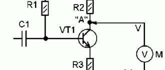
The first device was invented by Schweiger at the beginning of the 19th century, but it was then called a galvanometer. A drawing of a simple ammeter looks like this. On the axis of the bracket there is a steel anchor with an arrow. This structure is located parallel to a permanent magnet, which acts on the armature and gives it magnetic properties.
Lines of force run along the magnet and the arrow, which corresponds to the zero position on the scale. As soon as electric current begins to flow through the bus, a magnetic flux will be formed. Its field lines will be located perpendicular to the lines of the permanent magnet.
Under this influence, the armature will try to rotate 90°, and the magnetic flux will prevent it from returning to its original position. The interaction of magnetic fluxes depends on the magnitude and direction of the current that passes through the bus. According to this value, the needle will deviate from zero on the scale.
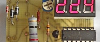
Chip CA3162E
BY42A can also be found in two board versions, but the color marking of the wires remains the same. To reduce the influence of ambient temperature on measurements, the additional resistor is made of a material with a low temperature coefficient of resistance. The connection can be made through a special socket connector, or using soldering. They contain a converter of the input signal into the angle of rotation of the arrow, showing on the scale the value of the measured voltage.
To also reduce the temperature factor during measurements, an additional resistor made of the same kind of material is connected in series with the ammeter coil. Connection Using a voltmeter, you can measure the current voltage in the power supply network.
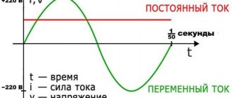
It is clear that a couple of amperes can be easily measured with a regular cheap multimeter, but what about 10, 15, 20 or more amperes? The scale readings are also multiplied by n. Homemade automobile voltmeter on microcircuits. If the connection is incorrect, the device display will show zero values. Receiving and transmitting alternating current is much easier than direct current: there is less energy loss. With the help of transformers, we can easily change the alternating current voltage.
CAE microcircuit for digital voltmeter and ammeter There are other microcircuits of similar action. Instrument transformers are depicted in the diagrams as ordinary transformers. A nuance when connecting a Chinese voltmeter and ammeter
See also: How to measure a phase zero loop
Application of devices
Electromagnetic types of devices are usually used in electrical equipment operating on alternating current networks with a frequency of 50 Hz. Magnetoelectric devices record small values of direct current. All ammeters according to reading devices are:
- with arrow indicator;
- with recording mechanism;
- electronic;
- with digital display.
To measure current in high-frequency electrical networks, thermoelectric devices are used, in which a thermocouple plays the role of a sensor. It records the degree of heating of the conductor when current flows through it. The frame responds to temperature , which is proportional to the current strength.
Electrodynamic devices are used to measure current in circuits with a frequency of up to 200 Hz. They are sensitive to overloads and extraneous electromagnetic waves. Due to the accuracy of measurements, they are used as control devices for checking other devices for measuring current strength.
More modern models are digital ammeters, which, according to physical indications, combine the advantages of analog instruments. Users can take measurements with them in any conditions, as they are not afraid of shaking, vibration, etc.
Non-contact devices include current clamps. They are constructed from a transformer head. With their help, values can be determined in any part of the electrical circuit. To do this, grasp the cable or wire being measured with pliers.
Chinese digital DC voltmeter up to 100V (direct current)
Price: $0.49 – 0.66 Hello, friends!
Today I will tell you about one very makeshift device that I made using two ultra-penny digital voltmeters, in which, in addition, you can also connect additional power. I warn you in advance that the product is no longer available from my seller (why is a mystery), so I provided a link to its analogue. Fundamental differences:
1) 5 backlight options instead of one; 2) yellow wire instead of white; 3) the arrangement of elements on the board has been changed; 4) the wires are soldered in a different place.
Otherwise the characteristics are identical:
- add. power supply from 3.5 to 30 Volts; — measurement range from 0 to 100 Volts; — there is a tuning resistor; — protection against incorrect connection of additional nutrition.
The dimensions of the voltmeters are extremely small, the BIOS battery is even larger in size.
On the reverse side, everything is soldered quite neatly and, judging by the shine, the soldering is lead-free (although I could be wrong).
The wires, alas, are iron. On the one hand - a minus, on the other - you can compensate for the error using a trimming resistor. By the way, for me it is located in the upper right corner of the board (under a Phillips screwdriver), and for the analogue, to which I gave a link, it is in the middle.
So, torture first.
The seller states that the voltmeter has protection against incorrect connection of additional components. nutrition, i.e. If you connect plus to minus, and minus to plus, then nothing will happen. I forgot to take a photo, but in practice it turned out that way. Next, I experimentally found out that the black wire is negative and the red wire is positive. In this case, the voltmeter is powered by a 3.7V lithium-ion battery. We see that the display is lit, i.e. There is power, but the display shows zeros.
Next, let's make control measurements of accuracy. To do this, we will use the reference voltage board (hereinafter referred to as RON), which is already known to you, which can output exactly 10V, 7.5V, 5V and 2.5V. I connected to the PON in the following way: I plugged a twist of two black wires (from the battery and from the voltmeter) into the negative PON, and the white wire into the positive PON. Also, as a control device, I connected a Uni-T UT33B multimeter, which I calibrated using the same board.
So, we see that our voltmeter clearly shows 2.5V and 5V, but 7.5V and 10V overestimates the readings by 0.1V.
Next, I started playing with the trimming resistor to figure out how and in which direction I could change the readings. It turned out that the resistor was twisted to the minimum, i.e. The readings can only be increased. In this case - up to 2.5V (+0.4V), 5.8V (+0.8V), 8.5V (+1V) and 11.5V (+1.5V). Those. The increase in stress is not linear, but parabolic.
Now the device itself. The black wires of both voltmeters were connected into one twist and crimped with an NShVI-shka. Next, I twisted the white and red wires in pairs (i.e., white + red twist from one voltmeter and the same from the other), and crimped the twists too. Now I’ll explain why.
I think, in the light of my latest reviews, you have already realized that I am quite keen not only on instruments, but also on computer electronics. Plus, I decided to do a little shopping on Avito. And with the help of these two voltmeters, it becomes much easier for me to monitor the voltage of the 12- and 5-volt power supply lines. And it looks something like this (only without a “control” multimeter):
As you can see, the multimeter shows almost exactly 5V, and one of the voltmeters shows 4.9V, which is not the norm. On the 12-volt line it’s even worse:
Agree, 11.8V when the actual 12.28V is too critical an error. not in order. It is necessary to additionally calibrate using a trimming resistor. As you can see, even PON did not help in this case.
As soon as I turned the trimmer resistor literally half a millimeter on the “12-volt” voltmeter, the readings changed sharply upward - immediately +1.9V.
Having suffered a little, I finally configured it so that it showed 12.3V, i.e. almost exactly as measured by a multimeter.
Next, I took another power supply, which I have been using since 2003 (yes, it is still alive, although a little dented and in need of a little repair). As you can see, he still keeps the voltages within normal limits.
Well, the third power supply, which I decided to test to the fullest on these voltmeters, is the 300 W LinkWorld . I think you remember that I gave him such a bad dressing down. And here are the results:
As you can see, the 5-volt line of the power supply is too high (the norm is no more than 5.25 V), and the 12-volt line, on the contrary, is too low. A 5-volt voltmeter shows 5.3V, which is quite true (since in real life it is 5.34V, but according to the rules of mathematics it is rounded to 5.3V). But the 12-volt voltmeter lies a little, adding 0.1V to the real readings. Not in order. We need to tweak it a little more. That's better:
Now I’ll explain why I started this device in the first place. There are power supplies that have protection against short circuits along the 12-volt line (i.e., the power supply simply turns off during a short circuit), but there is no such protection along the 3.3- and 5-volt lines. What does this mean? Here is the chronology of events:
— a short circuit occurs along the 5V or 3.3V line; — due to a short circuit, the voltage drops beyond the permissible limits; — The power supply unit does not understand that this is a short circuit and is trying to raise the voltage to normal; — at the same time, the voltage rises along the 12-volt line, going beyond the permissible limits; - due to the greatly increased voltage along the 12-volt line, the components simply burn out (the motherboard and everything connected to it come under attack (except for the cooling system - it will work normally at 16V).
And in order to make it easier for me to identify a similar malfunction (and in some cases, a design feature) in the power supply, it is necessary to SIMULTANEOUSLY monitor both the 5-volt and 12-volt lines. It was for this monitoring that I cobbled together such a device from two multimeters and NShVI tips. For greater convenience, it would be nice to find a Molex mother and solder the device on it so that you don’t constantly poke around with NShVIs, but this is a trifle.
[There is no need to monitor the 3.3V line - on most power supplies it has “group” stabilization with a 5-volt line. and in some cases, “group” stabilization occurs along all three lines, i.e. if the 12-volt one sag, then the rest will sag.]
Well, the most important thing is that calibrating a device using PON does not mean that the device will become super-accurate, because we saw even a voltmeter calibrated using PON with an inaccuracy of as much as 0.4 V.
Wisdom: Everything begins after the phrase “it’s over.”
Announcement: Friends, I found a rather interesting USB cable that increases the voltage from 5 to 12 Volts.
Popular models
Both domestic and foreign manufacturers produce quite a large number of devices of various classifications. Digital devices that are needed to measure readings are especially valuable. These include:
- A-05 (DC-2) - the device is designed with an external 75 mV shunt for measuring readings in DC voltage circuits. Depending on the transformer used, the ammeter is used in networks with a current of 100 to 1 thousand A. The unit of measurement is the ampere, measurements of which are obtained with an error of 1% if the shunt accuracy class is at least 0.5. Power consumption no more than 5 W.
- VAR-M01−083 AC 20−450 V UHL4 is a universal device used as both a voltmeter and an ammeter. The device can be used as main and additional equipment. It is powered by the electrical circuit being tested. The device has the function of storing the minimum and maximum values in memory. Control is carried out by one button, by switching which you can call up all functions.
- TDM SQ 1102−0060 400A/5A is an inexpensive pointer device used in single-phase networks. The housing is made of non-flammable plastic and is fully compatible with many transformer markings. The average service life is about 12 years.
- AM-1 is a stationary measuring device mounted on a DIN rail. An additional transformer is included in the kit. The measurement error is no more than 0.5 A.
Comparison of the presented models
The summary table contains brief parameters of the listed positions, namely:
| Model | Error, % | Voltage, V | Dimensions, mm |
| Strum! MM1204 | 1 | 600 | 230x160x60 |
| PeakMeter PM830L | 0.8 | 600 | 185x145x58 |
| FIT DMM8904 | 0.5 | 1000 | 205x180x42 |
| Mastech MY61 | 0.5 | 1000 | 91x189x31 |
| UNI-T UT15B | 0.4 | 690 | 70x255x28 |
| Megeon 12725 | 0.5 | 1000 | 88.5x190x27.5 |
| CEM DT-9918T | 0.3 | 1200 | 82x182x55 |
Measurement process
In practice, an ammeter is used much less frequently, but sometimes there is still a need to measure current. Typically, this procedure is used to determine the power of an electrical appliance if there are no corresponding designations. It is very important that when measuring current, the amount of voltage applied to the electrical circuit does not matter. Measurement with the device can be carried out by breaking the circuit anywhere.
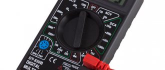
The source can be a simple 1.5 V battery, a 12 V battery, or a single-phase 220 V network. Before starting measurements, users prepare the equipment by moving the adjustment knobs to the appropriate starting position. If the approximate value of the current is unknown, then the switches are set to the maximum value.
When everything is prepared, an electrical device is connected to one of the sockets, and the ammeter wires to the other. If this is a household network, then the measuring device should set the alternating current and its maximum value. When measuring with pointer instruments, mistakes are often made, since the process itself is not very convenient to carry out with them.
In this case, it is much more convenient to use digital measuring devices. The M890G multimeters are very popular, which have two ranges for measuring both AC and DC current. Experienced electricians usually know approximately the parameters of the electrical network, so they immediately set the switches to the desired position.
If they do not know the value of the measured current, then they set the limit value on the multimeter to 10 A. Next, the device is reconfigured to a lower value corresponding to the network current.
It should be remembered that switching is carried out when the electrical circuit being tested is de-energized. Using a universal device that performs the task of a voltmeter and ammeter, the resistance of the connected device is indirectly measured. To do this, additional calculations related to Ohm's law are carried out.
An ammeter is a measuring device for determining current strength, measured in amperes. In accordance with the capabilities of the device, its scale has a graduation indicating microamps, milliamps, amperes or kiloamps.
Voltmeter rating
When using a measuring device, the accuracy of the readings is important. Small deviations can cause serious errors in calculations. In stores you can buy digital and analog models for electricians, electrical installers, and special developments for car owners. The VyborExperta.ru team decided to test the operation of the most common measuring devices. During testing, instrumental analysis methods were used, the opinions of professional electricians and user reviews were taken into account.
When compiling the review, the following characteristics of voltmeters were considered:
- Measurement range – the wider the interval, the more capabilities the instrument has;
- Functionality - additional functions, such as analysis of an alternating current sinusoid, are not always necessary at home, but can be indispensable for professional activities;
- Purpose – models are produced for networks with alternating and direct current, connection to the vehicle’s on-board electrical network, electrical distribution panels;
- Accuracy - each device has an error when measuring voltage, the smaller these values, the more accurate the data obtained;
- Size – a tool for stationary use will be inconvenient for working in the field.
Not all devices' declared characteristics corresponded to the passport data. Large errors, unstable readings - voltmeters with such parameters were excluded from our rating.
Connection diagrams
To carry out measurements, an ammeter is connected in series to the electrical circuit with the section where it is necessary to measure the current. To increase the measurement limits, the ammeter is connected through a shunt or transformer.
The most common is the ammeter circuit, where the moving needle rotates through an angle of inclination that is proportional to the magnitude of the force being measured.
Definition
An ammeter is a device that allows you to record current parameters.
Ammeter
A voltmeter is a device for obtaining current voltage readings.
Voltmeter
Voltmeter
Types of ammeters
According to their action, all ammeters are divided into electromagnetic, magnetoelectric, thermal, electrodynamic, detector, induction, photo- and thermoelectric. All of them are designed to measure the strength of direct or alternating current. Among them, the most sensitive and accurate are electrodynamic and magnetoelectric ammeters.
During operation of a magnetoelectric ammeter, a torque is created through the interaction between the field in a permanent magnet and the current passing through the frame winding. The arrow moving along the scale is connected to this frame. The arrow is rotated by an angle proportional to the current strength.
Rating TOP 7 best voltmeters
Today's TOP includes:
- Sturm! MM1204.
- PeakMeter PM830L.
- FIT DMM8904.
- Mastech MY61.
- UNI-T UT15B.
- Megeon 12725.
- CEM DT-9918T.
Details below.
Sturm! MM1204
from 380 to 450 rub.
7th place 4.1/5
DT-9918T is a professional-class measuring and diagnostic device, the strength of which is high measurement accuracy. It is possible to check the continuity of the circuit and check the diodes. An additional function is temperature measurement.
The device has a durable, shock-resistant housing that meets the IP67 protection degree. The last feature indicates the dust and waterproof properties of the device. You can use the multimeter in difficult conditions without fear of exposure to precipitation and other natural influences.
| Error | 1% |
| Voltage | 600 V |
| Dimensions | 230x160x60 mm |
- easy to operate;
- The shockproof housing corresponds to IP67 protection degree.
- no automatic mode;
- no cover.
A decent device in its price range. Made in a solid yellow body. It has a standard switch in the center and many metering modes. There is a separate “comport” for external control. The voltmeter is equipped with a beeper of medium quality, which allows it to produce characteristic sounds. I'm happy with the purchase, it's suitable for basic needs.
Sturm! MM1204
PeakMeter PM830L
from 650 to 799 rub.
6th place 4.2/5
The device is designed for measuring direct and alternating voltage, current, resistance of circuit elements, checking diodes and transistors, circuit integrity with sound indication.
This device with manual selection of the measurement range can be successfully used both during simple household operations and during extensive installation and commissioning work. The protective bumper increases the resistance of the device to all kinds of mechanical influences. The device is powered by just one nine-volt battery.
| Error | 0.8% |
| Voltage | 600 V |
| Dimensions | 185x145x58 mm |
- ergonomic mounts for probes;
- battery included.
- quiet beeper.
The probes are fixed at the back very conveniently, ringing occurs with sound. Overall the device is not bad. However, the display backlight only lights up for three to four seconds and then goes off. I suspect that this is an energy saving mode, but it’s not very convenient to somehow press the button every time to activate the backlight. But from the general impression I can say that it is simple and functional. I advise you to buy!
PeakMeter PM830L
FIT DMM8904
from 1,120 to 1,400 rub.
5th place 4.3/5
DMM8904 has all the functionality necessary even for professional measurements: it allows you to measure DC or AC voltage, DC or AC current strength and find out the resistance values of the entire electrical circuit or its components. The device will allow you to “ring” diodes and transistors and test the electrical circuit for integrity.
The model is equipped with a manual measurement range switch, which is located on the front panel immediately below the large and easy-to-read LCD display.
| Error | 0.5% |
| Voltage | 1000 V |
| Dimensions | 205x180x42 mm |
- ergonomic shape - body reinforced with rubber inserts;
- There is an input for an additional sensor.
- no cons found.
Comparing with cheaper analogues, I was convinced that taking a device from FIT was the right decision. The small case with rubberized inserts is very well made - comfortable to hold. There is an input for an additional sensor - for example, a thermocouple. There are 18 current measurement modes (from the smallest to the largest values). I'm happy with the purchase, I use it almost every day. You can take it!
FIT DMM8904
Mastech MY61
from 1,890 to 2,200 rubles.
4th place 4.4/5
This gadget has a wide range of functionality and is the best choice for both domestic and professional use. It can be used to measure voltage, current, resistance of circuit components and capacitance of capacitors in an electrical circuit.
In addition, the portable device shows the gain of transistors h21, makes it possible to check the integrity of the circuit, and can be used to test the performance of diodes. The device is equipped with a dark green protective bumper, measuring probes, and one 9 V Krona battery, which is used as a power supply.
| Error | 0.5% |
| Voltage | 1000 V |
| Dimensions | 91x189x31 mm |
- an automatic mode is provided - sensitivity selection occurs without human intervention;
- case included.
- inconvenient location of the battery compartment.
Personally, I liked it due to its small dimensions, good quality case and included batteries. Easy to use, automation helps if you don’t really understand how and what to measure. There are a minimum of control buttons, all are labeled or marked with pictures - even a child can handle them. The rubber-coated probes seem to be comfortable. Everything suited me.
Mastech MY61
UNI-T UT15B
from 2,150 to 2,600 rubles.
3rd place 4.5/5
UT15B – wide functionality in miniature. Built-in overload and overvoltage protection guarantee the device a long and productive service life and safety during use. Small size and weight, thanks to which the tester fits easily in your pocket and hand. A low base error and high sensitivity will help you cope in the most difficult conditions, because the gadget is designed to the highest standards.
| Error | 0.4% |
| Voltage | 690 V |
| Dimensions | 70x255x28 mm |
- there is a belt fastening;
- lightning-fast reaction when measuring;
- minimum basic error;
- operates at sub-zero temperatures (down to minus twenty Celsius).
- The operating manual is not in Russian.
The most convenient thing for its price. It does not fail, even in sub-zero temperatures it feels great and turns on without problems. The set includes a small case made of antistatic material with a strap on top - convenient to hook onto your belt. By the way, there are also batteries - you don’t need to buy them separately. The display is small, but there are only two icons and three digits for numbers. The sensitivity is high, it reacts quickly, there is a beeper. The thing is good, you can take it.
UNI-T UT15B
Megeon 12725
from 3,450 to 3,900 rub.
2nd place 4.7/5
This device is used to measure the parameters of an electrical circuit. When a thermocouple is connected, the portable device can also be used to measure the temperature of various objects. The device also makes it possible to test the integrity of the electrical circuit and test diodes. It displays the results of the measurements on the LCD display.
The professional-grade 12725 supports manual range selection using a rotary switch on the front panel. The device is equipped with a shockproof bumper, probes and a thermocouple.
| Voltage | 1000 V |
| Error | 0.5% |
| Dimensions | 88.5x190x27.5 mm |
- a thermocouple and a bumper are included;
- measures the inductance of circuit elements, current frequency;
- color LCD display.
- There are a lot of fine adjustments that a beginner will not be able to cope with.
I use it as my main working tool. Well, what can I say. Quite a quick call, little thought. The resistance shows, the diodes light up. Calculates the mean square, minimum, maximum (if the indicator fluctuates) current, voltage, frequency, resistance, temperature. Capacitance actually measures up to 10 thousand microfarads. I'm happy with the purchase, I recommend it!
Megeon 12725
CEM DT-9918T
from 5,130 to 5,550 rub.
1 place 4.9/5
CEM DT-9918T is a professional-class measuring and diagnostic device, the strength of which is high measurement accuracy. A multimeter with a traditional control panel will allow you to measure DC and AC voltage.
The device has a durable, shock-resistant housing that meets the IP67 protection degree. The last feature indicates the dust and waterproof properties of the device. You can use the multimeter in difficult conditions without fear of exposure to precipitation and other natural influences. There is a screen backlight, thanks to which you can use the device in any lighting conditions.
| Voltage | 1200 V |
| Dimensions | 82x182x55 mm |
| Error | 0.3% |
- included in the register of measuring instruments - will show the most accurate measurements;
- device for professionals;
- degree of protection IP67;
- minimum permissible error 0.3%.
- no deficiencies were found.
There is a temperature sensor, I tried it - it works, but somehow I don’t really need it. There is a frequency measurement mode, but I haven’t tried it yet. I haven’t measured the currents yet either, there was no need. The main advantage is that this device is included in the register of measuring instruments, so you can argue with someone if different devices show different values in the same case. In a word - a professional thing, worth the money.
CEM DT-9918T
Principle of operation
A simplified classical ammeter circuit works as follows. In parallel with the permanent magnet, a steel armature with an arrow is installed on the axis of the bracket. A permanent magnet, acting on the armature, gives it magnetic properties. In this case, the location of the armature runs along the lines of force, which also run along the magnet. This position of the anchor corresponds to the zero position of the arrow on the instrument scale.
After the discovery of electric current, the need arose to measure it. Despite the fact that the first prototypes of the devices were not very accurate, the principle of their operation has not changed for several centuries. Today, an ammeter is used for measurements - this is a device that measures the strength of electric current.
Origin story
By the name of the device you can guess who had a hand in its creation. André-Marie Ampère was a brilliant scientist of his time who devoted many years to electrodynamics. He is responsible for many significant discoveries in this area:
- interaction of magnetic field and electric current;
- magnetic effect of a current-carrying coil;
- introduction to scientific terminology of the concepts of cybernetics and kinematics.
The scientist’s main merit is not the development of the device, but the preparation of a scientific springboard for the very possibility of creating an ammeter and voltmeter. Therefore, the first mentions of the measuring device date back to the 20s of the 19th century, when Ampere himself was already over 50.
Then we were talking about the simplest device - a galvanoscope, consisting of a twisted wire and a magnetic needle. It made it possible to capture relative indicators based on the degree of deviation of the needle.
Over the next decades the design was improved. In 1884, domestic scientists developed more advanced devices, but the patents were transferred to Germany due to the insufficient development of electrical production. Only by that time were the names of modern quantities approved. In 1881, in relation to current, a decision was made about how force was measured - in Amperes.
How do ammeters work today? The housing with the indication contains a measuring coil and permanent magnets that align it when an electric current is applied. The stronger the deviation, the higher the indicator of the device. There are several varieties, differing in design and scope.
For your information. The classic type is a device with a scale, the divisions of which indicate the current strength in Amperes. Depending on the value, the moving element rotates the arrow at a certain angle.
ELECTROMAGNETIC AMPERMETERS AND VOLTMETERS
The operating principle of electromagnetic system devices is based on the interaction of a magnetic field created by a current in a stationary coil with a movable ferromagnetic core drawn into the coil with current. The energy of the magnetic field of a coil through which a direct current I flows
Substituting the energy value Wem into the generalized scale equation (formula 3.2) for electromechanical mechanisms, we obtain
If an alternating current i(t) flows through the coil, then, due to the inertia of the mechanism, time averaging occurs, i.e. we can write the scale equation in the form
By definition, the effective value of the current
,
those. the equation will take the form
. (3.6)
From formula 3.6 it follows that the angle of rotation of the moving part of the mechanism is proportional to the effective current value, i.e. does not depend on the direction of the current. Therefore, electromagnetic instruments are suitable for measuring direct and alternating currents and voltages. From the scale equation (3.6) it is also clear that the scales of these devices are nonlinear, and partial linearization is carried out by choosing a special shape of the movable ferromagnetic core.
Ammeters. In electromagnetic ammeters, the coil of the measuring mechanism is connected directly to the open circuit of the measured current.
Panel ammeters are produced with one measurement limit, portable (laboratory) ones can have several measurement limits. In this case, the limit is selected by switching sections of the coil winding, turning them on in series or in parallel.
Shunts are not used in these ammeters, because the coil has very low self-resistance.
When measuring large alternating currents, measuring current transformers are used (§ 3.2).
When using ammeters in DC circuits, an error appears due to the hysteresis of the magnetization of the core. To reduce this error, the cores are made of soft magnetic materials, for example, permalloy.
When the frequency of the measured current in ammeters changes, a frequency error occurs due to the action of eddy currents in the core and other metal parts of the mechanism, penetrated by the magnetic flux of the coil.
The industry produces ammeters with current limit values from fractions of an ampere to 200 A.
For indirect connection of ammeters through current transformers, 5 A ammeters are most often used.
Voltmeters. If we take into account that the current through the coil winding of the device, where U is the applied voltage, and Zpr is the absolute resistance, then from formula (3.6) we obtain the scale equation for electromagnetic voltmeters
.
That. electromagnetic voltmeters measure the effective value of voltage, but their readings depend significantly on frequency, because The voltmeter coil has a higher inductance than the ammeter to produce the required torque. Expanding the measurement limits is carried out using a set of additional resistors (§ 3.2), which simultaneously increase the input resistance of the voltmeters.
The general advantages of electromagnetic devices include:
— simplicity of design;
— reliability;
— ability to withstand heavy overloads;
— suitability for use in direct and alternating current circuits;
- low cost.
Flaws:
— large own energy consumption (units of watt);
— low accuracy;
- low sensitivity;
— strong influence of external magnetic fields, because the field of the coil with current is small, like that of a solenoid without a core.
ELECTRODYNAMIC DEVICES
The operating principle of electrodynamic devices is based on the interaction of the fields of two coils with currents, one of which is stationary.
Electrokinetic energy of two coils with currents
,
where L1 and L2 are the inductances of the moving and fixed coils, I1 and I2 are the currents in these coils, and is the mutual inductance of the coils.
Only the mutual inductance M depends on the angle of rotation, then, taking into account formula (3.2), we obtain the scale equation in the form
, (3.7)
those. The mechanism of the electrodynamic system is, in principle, a multiplying electromechanical device.
If alternating currents flow through the coils, for example, sinusoidal
And ,
then the scale equation will be written in the form
, (3.8)
where j = j1 - j2 is the phase shift angle between the currents in the coils.
That. The deflection angle of these mechanisms at alternating currents i1 and i2 depends on the product of the currents and their phase difference. This makes it possible to use electrodynamic system devices not only as ammeters and voltmeters, but also as wattmeters, and with the use of two movable frames fastened together at a certain angle (logometers) - as phase meters.
Ammeters. In ammeters, the coils can be connected in series (Fig. 3.8) or in parallel. Parallel connection is used for ammeters with relatively high currents (up to 10 A).
Series connection is used in milliammeters and ammeters up to 0.5 A. Such currents are not capable of damaging thin current-carrying springs.
In the series ammeter circuit I1=I2=I, φ1-φ2=0, the scale equation for alternating currents (3.8) is reduced to the form
,
those. provided that the angle of rotation of the arrow depends quadratically on the current flowing in the coils. Therefore, the effective value of the current will be measured. However, the scale is nonlinear, and to linearize it, the shapes and arrangement of the coils are selected in such a way that it does not remain constant, but depends significantly on the angle between the moving and fixed coils.
In a parallel circuit of ammeters, I1=k1I and I2=k2I, and the phase difference is also ensured that it is zero by installing additional inductances in the circuits of the main coils. Electrodynamic ammeters have frequency errors, because the total impedance depends on the frequency of the current. However, at present these are the most accurate instruments for measuring alternating currents of industrial frequency in the range from 10 mA to 10 A.
Voltmeters. To increase the internal resistance, both coils of voltmeters are connected only in series using an additional resistor RDOB (Fig. 3.9), which reduces the current through the device. When the coils are connected in series I1=I2=I, with the total resistance of the device circuit Zп=Z1+Z2+RDOB, taking into account formula (3.7), the voltmeter scale equation will take the form
.
As in the case of ammeters, the change achieves an almost uniform scale for voltmeters.
Typically, voltmeters are made multi-range using additional resistors. Used for direct measurement of voltages up to 600 V.
When measuring high voltages, voltage measuring transformers are used (§ 3.2).
Electrodynamic voltmeters have frequency errors that can be calculated using the formula
,
where δf is the relative frequency error at frequency f, τ=LV/RV is the device constant, LV is the total inductance of the coils, RV is the total resistance of the voltmeter taking into account RDOB.
It is possible to correct the frequency and compensate for the frequency error (δf=0) at the frequency , where SDOB is a capacitance connected in parallel with the additional resistor.
Wattmeters. When constructing wattmeters, they use the fact that the deflection angle of the electrodynamic mechanism is proportional to the product of the currents in the coils (see formula 3.7).
From Fig. 3.10 it can be seen that the circuit for switching on the wattmeter coils, when the power consumed by the load ZH changes, ensures the multiplication of currents and I1 = IH. The moving coil is connected in parallel as a voltmeter, and the stationary coil is connected in series as an ammeter. Taking this into account, the scale equation for the wattmeter is
,
where ZV is the total resistance of the volt winding, cos φ is the phase shift angle between the current and voltage in the load.
The wattmeter scale equation is linear, and the readings will be proportional to the active power. The accuracy classes of multi-limit laboratory wattmeters are quite high (0.2, 0.1). The range of measured powers is from several watts to several kilowatts. Measurements can be performed both on direct current and on industrial frequency currents.
Errors in electrodynamic wattmeters arise due to temperature influences and the presence of external magnetic fields. As the frequency increases to several hundred hertz, frequency errors also become significant due to an increase in the inductive reactance of the coils, leading to a decrease in torque.
To increase sensitivity and reduce the influence of external magnetic fields, a fixed coil can have a soft magnetic core, between the poles of which a moving coil is placed. The devices are also called ferrodynamic.
Electrodynamic ratiometers. In ratiometric measuring mechanisms, the moving part is made in the form of two coils rigidly fastened together, placed inside a stationary coil with current I. Currents I1 and I2 flow through the windings of the moving coils, which are supplied using metal tapes that have practically no counteracting torque (Fig. 3.11).
The torques created by the action of a stationary coil with current I with the magnetic fields of moving coils with currents I1 and I2 are directed in the opposite direction. That. the moment of the first coil is rotating, the moment of the second is counteracting. The scale equation takes the form
,
if we ensure the equality I1 = I2 in absolute value, then the instrument scale can be calibrated in φ or cosφ. Such devices are used to measure cosφ - phase meters and to measure frequencies - frequency meters. The latter use the dependence of the deviation angle on the resistance ratio in the circuits of the moving frames, i.e. . If, for example, I2 does not depend on frequency, then when a capacitor is added to the moving winding circuit, Z1 changes due to resonance. Therefore, the instrument scale can be calibrated in frequency units, because .
Electrodynamic frequency meters are produced for measuring frequency in a narrow range (45-55, 450-550 Hz), accuracy classes 1, 1.5. Phase meters - in the form of portable devices with a measurement range of angle φ from 00 to 900 and cosφ from 0 to 1 for inductive and capacitive loads, accuracy classes 0.2, 0.5.
Types of ammeters
Devices can be classified according to their display method. The most widely used analog ammeters are those with a graduated scale along which the needle moves. Modern devices have a digital display that displays the current value.
Instruments with pointer head
Pointer ammeters are gradually disappearing. They are more complex in design than modern models and have a limited scope of application. Another disadvantage is the shorter lifespan due to the presence of more mechanical parts. At the same time, modern conditions sometimes require measuring smaller quantities than is required to deflect the arrow even by one division. Because of this, pointer instruments have to be modified with signal amplifiers.
Interesting. For a long time, these devices had no analogues - the measurement accuracy was quite high. However, the development of the electrical industry has made it possible to develop devices that are cheaper to manufacture.
Operating principle of the pointer head
Another difficulty when using a pointer ammeter is the principle of operation of the pointer, which differs in different measurement systems:
- Magnetoelectric. The arrow rotates along a linear scale proportional to the current strength. The torque is set by the current passing through the frame winding.
- Electromagnetic. The arrow is attached to a ferromagnet core, which moves inside the coil.
- Electrodynamic. Two coils are used with a serial or parallel connection. On the movable one there is an arrow fixed, which rotates due to the interaction between the currents of the coils.
All types of devices use a corrector - a special screw connected to a spring. It is necessary to set the arrow to the zero position.
Which voltmeter is better
The market offers domestic and European products, as well as brands from China, the United States, South Korea and Japan. The equipment differs in prices, format, and measurement accuracy. Some of the equipment is highly specialized. For these reasons, choosing one universal model is difficult. The VyborExperta.ru team recommends taking into account the scope of application, working conditions, and accuracy of measuring instruments. Experts recommend the following models:
- Airline AVM-D-02 – for monitoring the vehicle’s on-board network;
- Orion NV-01 – to check battery characteristics;
- Digitop AVM-1 – for professional use;
- TDM Electric TsP-V72x3 – digital model for the distribution panel;
- IEK 47 is an analog panel instrument with a wide measuring range.
All presented devices are distinguished by high measurement accuracy, functionality, and an easy-to-use format. Devices with increased reliability, capable of stable operation for several years, deserve the title of the best in their categories.
Ammeter device
The ammeter is based on the interaction between two elements during the passage of electric current. Depending on what the ammeter measures, different device options are used. Measuring the strength of different types of current requires a special structure and sensitivity. There are several categories:
- Magnetoelectric. It is based on a moving coil mounted on an axis between two magnetic poles.
- Electromagnetic ammeters use a core that is moved away by a distance proportional to the current strength.
- Thermoelectric. The key element is a thermocouple soldered to the wiring. The amount of heating as current of different magnitudes is supplied is transformed into an indicator of its strength, after which it is displayed on the display.
- Electrodynamic. Moving and fixed coils. They are of little use in everyday life due to their high sensitivity to magnetic fields. Used for precise measurements or for demonstration purposes.
- Ferrodynamic. The most accurate and expensive of mechanical instruments. Thanks to the closed wire, they do not react to external magnetic fields.
- Digital. An integrator is used that converts the current value into a digital equivalent. How ammeters work depends on its type and setting. There are several accuracy classes based on measurement error.
Despite the differences in design, all mechanical devices are based on a common operating principle.
Small built-in voltmeter
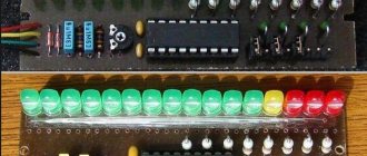
I bought a couple of tiny voltmeters. They are very popular, so there are a lot of options for them. I took the smallest ones with a two-wire connection, a red one and a green one.
The colors of the glow in the photo are greatly distorted, in reality they are quite normal for LEDs. In bright external lighting, reading readings is difficult; voltmeters may need to be installed in a recess.
Both voltmeters show voltage almost identically, the difference is beyond the display step (0.1 V for voltages of 10 V and 0.01 for less). And both show a lower value than my old household multimeter, which makes me think that its calibration has gone wrong. This is also confirmed by the ADC readings of my Arduinos, Pro Mini and Nano. I don’t have a reference voltage source, and buying one for home purposes is a bit expensive, but if the other 5 devices of a similar level show a lower voltage, then the sixth one is probably wrong.
Sellers claim accuracy for these voltmeters in the range of 0.1%-1% or 0.1V depending on the chutzpah. It is not known who is guided by what, but I would pay attention to the accuracy of the ADC of the microcontroller used without taking into account calibration over the entire range. It would be cool if the manufacturer calibrated such voltmeters. Although even the simplest microcontroller probably has all the possibilities for this, it’s hard to believe in such concern for the buyer of an extremely cheap device. A trimmer can compensate for ADC offset error, but it is not the only or worst type of ADC error.
Depending on the type of connection, there are two types of such voltmeters - two-wire and three-wire. Two-wire ones are powered directly from the line being measured, hence there is a limitation - they can only measure voltages above 2.5-3.5 V (depending on the implementation) and below the maximum input voltage of the built-in converter, approximately 30-40 V, both of mine have a limit of 30 B. The three-wire circuit typically measures voltages from 0 to 100 V, but requires a power supply. One of the purchased voltmeters works starting from 2.5 V, and the other from 3.5 V, but the display of the first one reaches normal brightness only at the same 3.5 V.
The design of the device is simple. This is one simple microcontroller and display. Sometimes there is also a trimming resistor for calibration, but given the nature of all possible distortions in the ADC of microcontrollers, this makes almost no sense, and can be a source of additional error.
One of the purchased voltmeters has a calibration potentiometer, but the second does not, the first has the MK marking erased, the second has STM8S003F3P6 (ADC capacity 10 bits). I put the second one in the screwdriver battery, where it can be subject to shocks and vibrations, which means there is no need for an extra moving element.
The readings are updated several times per second. When turned on, the first measurement takes less than a second. In the battery for the drill/driver, I installed one of these voltmeters through a push-button switch without locking. It is enough to press the button and hold it for a second to see the battery voltage, it turned out conveniently, although a faster switching on (up to 200 ms) would have looked much better.
The following colors are available: red, green, yellow, blue. Depending on the implementation, the display may flicker at a higher or lower frequency. My green flickers at a high enough frequency that it's almost unnoticeable, but the red one makes it very noticeable. I couldn’t determine for myself which option is better readable when shaking, but stationary it doesn’t really matter.
Dimensions are 0.28″, 0.36″, 0.56″, the numbers indicate the height of the characters in inches, in my case it is 0.28″ = 0.28*25.4 = 7.1 mm. The size of the entire device usually exceeds the size of the display only by the size of the mounting loops, if any. Here (size 0.28″) the display dimensions are 22.5 mm by 10 mm. The depth is about 10 mm, depending on the build quality; in one of my voltmeters the display is soldered crookedly, which increased the overall dimensions of the entire device.
You can find it in stores using phrases like “mini voltmeter”, “micro voltmeter”, “0.28 voltmeter”, etc. The smallest ones are more expensive than the larger ones. For example, I found mine for at least $1.7, and a slightly larger size costs 1.4, different colors cost differently, usually red is the cheapest.
Update (January 2015)
I bought another small voltmeter, it came with the same version that I put in the screwdriver battery, now I have the opportunity to take a photo.
This option has shorter wires than the green one. They are also soldered on the display side, which will make them difficult to replace if necessary.
Operating principle
The measurement method is based on the operation of several elements:
- On the axis between the permanent magnets there is an armature with an arrow.
- Thanks to the influence of magnets, the steel anchor is located along the power lines, in the zero position.
- When current is applied, a magnetic flux appears with lines of force perpendicular to the magnets.
- As a result of this effect, the armature tends to turn at a right angle, which is prevented by the main magnetic field.
- The final deviation of the arrow is the result of the interaction of two flows.
Due to the simple principle of operation of the ammeter, mechanical devices for a long time differed only in the material used to make the elements.
Operating principle of an ammeter
The operation of different types of ammeters is based on different operating principles. The methods used to measure electric current mainly depend on the application of the device.
The principle of operation of a magnetoelectric ammeter is based on the fact that a constant magnetic field and electric current flowing through the windings of the frame cause the occurrence of torque. The flow of electric current through the device causes the needle to move. The latter is directly connected to the frame. Therefore, the angle of rotation of the arrow is directly proportional to the amplitude of the measured electric current.
The design of an electrodynamic ammeter includes a fixed and moving coil. To measure currents of small magnitude, they are connected in series, and for large currents - in parallel. The needle is attached to the moving coil and moves as a result of the interaction between the currents flowing in the fixed and moving coil.
The design of a thermoelectric ammeter is based on a magnetoelectric device with a contact or non-contact transducer. The latter is a conductor with a thermocouple welded to it. Passing through the converter, the electric current causes it to heat up, which is detected by a thermocouple. The resulting thermal radiation affects the magnetoelectric device. Its frame deviates by an angle proportional to the value of the flowing electric current.
The operation of a digital ammeter is based on analog-to-digital conversion of the amplitude of the measured current. Passing through an analog-to-digital converter (ADC), the signal is quantized by time and then by level. The received information is converted into digital form and displayed on the display.
How to connect an ammeter
For correct connection, it is necessary to study the ammeter circuits in different types of circuits. For different currents, there are different types of devices - a distinction is made between AC and DC ammeters. To connect a DC ammeter, you need to consider the measuring range by determining the maximum current level.
The main thing is not to connect the device in parallel. In this case, there is a high probability that it will burn out. This is due to the low internal resistance of the ammeter.
Application of ammeters:
Ammeters are used in industry, telecommunications, laboratory research and other fields of activity to measure direct or alternating electric current in the range from units of μA to tens of kA. In this case, the value of the measured current should not exceed the maximum scale value of the device, taking into account the connection diagram. Depending on the measurement limit, modern ammeters are divided into:
- microammeters;
- milliammeters;
- ammeters;
- kiloammeters.
Ammeter internal resistance
It should be less than the resistance of the circuit itself. The indicator is calculated after measurements with a voltmeter, which is connected in parallel with the ammeter. Then the readings of the second are divided by the readings of the first, the result is internal resistance. A small value is necessary so that the voltage drop across the device does not affect the accuracy of measurements.
This device is one of the simplest and most common. How to use ammeters is taught in physics lessons, so there should not be any special problems during operation, especially with the advent of digital ammeters, which have significantly simplified the nuances of working with the device and expanded the scope of its application.
Digital voltmeter modules
The big advantage of the blocks is the relatively low price and the absence of supply voltage; they are powered by a voltage that is simultaneously measured. The manufacturer gives a voltage range of 2.6 - 30 V. First, let's test them at different voltage values. Powered by converter and lithium-ion batteries. We will compare the readings with the UNI-T UT210E meter, as well as with ANENG. The modules have a small potentiometer on the board to correct the readings.
It happens that tuning a module at low voltage also requires correction in the upper operating ranges of this module. To increase accuracy, you can use the potentiometer to calibrate the readings against a reference device and after the procedure, we recommend adding a drop of nail polish to immobilize it. After calibration they will become quite accurate.
The accuracy of these indicators will be acceptable in many devices, especially considering the low price of these modules (can be purchased for less than 100 rubles). The indicators automatically switch the range - after exceeding the value of 9.99 V, only decimal parts are displayed, that is, one digit after the decimal point.