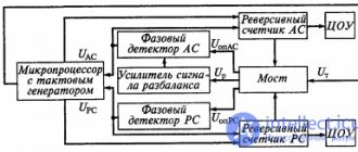
What is AC voltage?
As you know, electric current is the ordered movement of charged particles that occurs under the influence of a potential difference or voltage. One of the main characteristics of any type of voltage is its dependence on time. Depending on this characteristic, a distinction is made between constant voltage, the value of which practically does not change over time, and alternating voltage, which changes over time .
To assemble a radio-electronic device, you can pre-make a DIY KIT kit using the link.
Alternating voltage, in turn, can be periodic or non-periodic. Periodic voltage is a voltage whose values are repeated at regular intervals. Non-periodic voltage can change its value at any time period. This article is devoted to periodic alternating voltage.
Constant (left), periodic (center) and non-periodic (right) alternating voltage.
The minimum time during which the alternating voltage value is repeated is called period . Any periodic alternating voltage can be described by some functional relationship. If time is denoted by t, then such a dependence will have the form F(t), then in any period of time the dependence will have the form
where T is the period.
The reciprocal of the period T is called the frequency f. The unit of frequency is Hertz and the unit of period is Second
The most common functional dependence of periodic alternating voltage is a sinusoidal dependence, the graph of which is presented below
Sinusoidal alternating voltage.
It is known from mathematics that a sinusoid is the simplest periodic function, and all other periodic functions can be represented as a number of such sinusoids having multiple frequencies. Therefore, it is necessary to initially consider the features of sinusoidal voltage.
Thus, the sinusoidal voltage at any time, the instantaneous voltage , is described by the following expression
where Um is the maximum voltage value or amplitude,
ω – angular frequency, rate of change of argument (angle),
φ – the initial phase, determined by the displacement of the sinusoid relative to the origin, determined by the transition point of the negative half-wave to the positive half-wave.
The quantity (ωt + φ) is called phase , characterizing the voltage value at a given time.
Thus, the amplitude Um, angular frequency ω and initial phase φ are the main parameters of the alternating voltage and determine its value at each moment of time.
Usually, when considering a sinusoidal voltage, it is considered that the initial phase is zero, then
In practice, quite often, a number of other parameters of alternating voltage are used, such as effective voltage, average voltage and shape factor, which we will consider below.
Ohm's law.
The basic law that guides radio amateurs is Ohm's Law.
.
Georg Simon Ohm Georg Simon Ohm, 1787–1854 German physicist. Born in Erlangen on March 16, 1787 (according to other sources, he was born in 1789). Graduated from a local university. He taught mathematics and natural sciences. In academic circles he was recognized quite late. In 1849 he became a professor at the University of Munich, although already in 1827 he published the law that now bears his name. In addition to electricity, he was engaged in acoustics and the study of human hearing. Georg Ohm experimentally established that the strength of the current I flowing through a homogeneous metal conductor (i.e., a conductor that is not affected by external forces) is proportional to the voltage U at the ends of the conductor. I = U/R, where R is the electrical resistance of the conductor. This equation expresses Ohm's law for a section of the circuit
(not containing a current source).
The formulation of this law is as follows: The current strength in a section of a circuit is directly proportional to the voltage at the ends of this section and inversely proportional to its resistance.
The SI unit of electrical resistance is called the Ohm in honor of this eminent scientist. The resistance of a conductor will be 1 Ohm if, with a current of 1 Ampere flowing through it, the voltage drop across it will be 1 Volt. Also, when current passes through a conductor, power is released on it (it heats up), and the greater the current flowing through it, the greater the power released on it. As you should know, U is the work done when moving one coulomb, and the current I is the number of coulombs passing in 1 second. Therefore, the product of current and voltage shows the total work done in 1 second, that is, electrical power or the power of electric current in Watts. Conclusion: since the electrical power “P” equally depends on the current “I” and on the voltage “U”, then, therefore, the same electrical power can be obtained either with a high current and low voltage, or, conversely, with high voltage and low current. From all this, the following formulas for calculating current, voltage, resistance, and power follow. The quantities entered in these formulas are; voltage in volts, resistance in ohms, current in amperes, power in watts.
The last formula determines the current power and was derived on the basis of practical experiments carried out in 1841 by D. P. Joule and independently in 1842, by the experiments of E. H. Lenz. It is called the Joule-Lenz Law. It sounds like this;
The amount of heat released per unit time in the section of the circuit under consideration is proportional to the product of the square of the current in this section and the resistance of the section.
To determine all these quantities, there is a very interesting diagram (table) that reflects all these formulas. In the center are the required quantities, and in the sectors with the corresponding colors are possible solutions depending on the known quantities.
There is an even more simplified diagram for determining quantities based on Ohm's law. Commonly called Ohm's triangle. It looks like this:
In this Ohm triangle, you need to close the desired value, and the other two symbols will give the formula for calculating it. Ohm's law also applies to the entire circuit, but in a slightly modified form:
,
- - EMF of the circuit,
- I
is the current strength in the circuit, - R
is the resistance of all circuit elements, - r
is the internal resistance of the power source.
Ohm's law for a complete circuit sounds like this: The current strength in the circuit is proportional to the EMF acting in the circuit and inversely proportional to the sum of the circuit resistance and the internal resistance of the source.
What is AC rms voltage?
As I wrote above, one of the main parameters of alternating voltage is the amplitude Um, however, it is not convenient to use this value in calculations, since the time interval during which the voltage value u is equal to the amplitude Um is negligible compared to the period T of the voltage. Using the instantaneous voltage value u is also not very convenient due to the large volume of calculations. Then the question arises, what value of alternating voltage should be used in the calculations?
To solve this issue, it is necessary to turn to the energy that is released under the influence of alternating voltage and compare it with the energy that is released under the influence of constant voltage. To solve this issue, let us turn to the Joule–Lenz law for constant voltage
For alternating voltage, the instantaneous value of the released energy will be
where u is the instantaneous voltage value
Then the amount of energy for the full period from t0 = 0 to t1 = T will be
By equating the expressions for the amount of energy at alternating voltage and constant voltage and expressing the resulting expression in terms of constant voltage, we obtain the effective value of alternating voltage
The resulting expression allows you to calculate the effective value of voltage U for a periodic alternating voltage of any shape. From the above, we can conclude that the effective value of an alternating voltage is called a constant voltage that, in the same time and at the same resistance, releases the same energy that is released by a given alternating voltage.
Effective value of sinusoidal voltage.
Let's calculate the effective value of the sinusoidal voltage
It is worth noting that all voltages of electrical devices are determined, as a rule, by the effective voltage value.
To determine the amplitude value of the sinusoidal voltage, it is necessary to transform the resulting expression
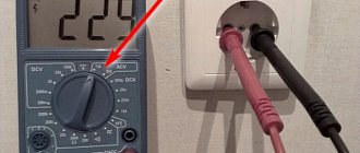
Thus, if we have U = 230 V in the socket, therefore, the amplitude value of this voltage
Effective voltage is also called effective voltage and root mean square voltage.
We've sorted out the effective voltage, now let's look at the average voltage.
Electrical measurements.
Let's draw a simple electrical circuit consisting of a battery “B” and a load “R”, and consider how it is necessary to measure the current flowing through the circuit and the voltage across the load.
To measure the current flowing in the circuit, it is necessary to connect a measuring device (ammeter) to the gap between the power source and the load.
In order to have as little influence on the measured circuit as possible and to increase the measurement accuracy, ammeters are made with a very low internal resistance, that is, if you include an ammeter in the open circuit of the circuit being tested, it will practically not add additional resistance to the measured circuit, and the flowing along the circuit, the current will practically not change, or will decrease by a very small amount, which will not have a significant effect on the final measurement result.
Therefore, it is strictly forbidden to measure the “current flowing to the load” by connecting an ammeter in parallel with the load, or directly at the power source (without load) and thus try to measure the output current supplied by the power source or lighting network.
This is equivalent to connecting a regular wire in parallel with the load or power source. To put it simply, short-circuit the circuit. If the power source has good power, there will be a very strong B A X !!! The consequences can be very different, from failure of the measuring device (ammeter), which usually happens, to knocked out plugs (gas stations) in the apartment and loss of power to the room and possible electric shock. To measure the voltage across a load, it is necessary that the voltmeter connected to it does not shunt the load and does not have a noticeable effect on the measurement result. To do this, voltmeters are made with a very high input resistance and, on the contrary, they are connected in parallel to the circuit being measured. Due to the high input resistance of the voltmeter, the resistance of the measured circuit practically does not change, or changes very little, without having a noticeable effect on the measurement result. The figure above shows the procedure for connecting an ammeter and a voltmeter to measure the voltage across the load and the current flowing through it. The polarity of connecting measuring instruments to the measured circuit is also indicated.
What is the average value of AC voltage?
Another parameter of alternating voltage that characterizes it is the average value of alternating voltage. Unlike the effective value of alternating voltage, which characterizes the operation of alternating voltage, the average value of voltage characterizes the amount of electricity that moves from one point in the circuit to another under the influence of alternating voltage. The average voltage value over a period is determined by the following expression
where T is the period of alternating voltage,
fu(t) – functional dependence of voltage on time.
Thus, the average value of the alternating voltage will be numerically equal to the height of a rectangle with a base T, the area of which is equal to the area limited by the function fu(t) and the Ox axis for the period T.
Average value of alternating voltage.
In the case of a sinusoidal function, we can only talk about the average value over a half-cycle, since during the entire period the positive half-wave is compensated by the negative half-wave, and then the average voltage over the period will be zero.
Thus, the average value of the sinusoidal alternating voltage over the half-cycle T/2 will be equal to
where Um is the maximum voltage value or amplitude,
ω – angular frequency, rate of change of argument (angle).
4.1.4. On the calibration of electronic voltmeters.
From the above it follows that to measure different signal parameters, various voltmeters are used, which respond either to the peak, or to the average-rectified, or to the root-mean-square voltage value of the measured signal. The type of parameter being measured is determined by the type of converter used in the voltmeter. When measuring the peak value, use a voltmeter with a peak converter, to measure the average rectified value, use a voltmeter with an average-rectified value converter, and for the root-mean-square value, use a voltmeter with a quadratic converter. However, the scales of most electronic AC voltmeters are usually calibrated in RMS voltage values of a harmonic signal (sinusoidal waveform). In this case, only the readings of a voltmeter with an RMS value converter are equal to the measured parameter for any form of the measured signal. The readings of voltmeters with other types of converters are determined by the relationship:
UVi = C gr
i × Ux
;
(4.12)
where UVi
is
the reading of the corresponding voltmeter;
C gr i
is the calibration coefficient of this voltmeter;
Ux
is the voltage parameter to which this voltmeter responds.
Table 4.2
№
p/p
“Fighting error”
There are three main reasons due to which fluctuations in measured effective values occur. We just talked about the first two:
- Measurement error of higher harmonics
- Frequency deviation from 50 Hz.
- Presence of noise-like and impulse interference.
All three lead to measurement error.
To combat these phenomena, NPSI converters can enable averaging of measured values. This simple and effective method makes it possible to almost completely eliminate these fluctuations, but its use leads to increased measurement inertia. Primary averaging occurs at an interval of 80 ms when measuring the most effective value. In addition, NPSI converters provide an additional averaging option with averaging times from 1 s to 50 s, but additional averaging can be disabled.
The user should choose the optimal balance between error and performance.
Three phase current
A three-phase system is an electrical circuit system operating on three circuits in which forces of the same frequency act, but are out of phase from each other by one-third of a period or 120 degrees. Each individual circuit of such a system is called a phase, and a system of three phase-shifted currents is called three-phase current.
You might be interested in WAGO connectors
Almost all modern generators in homes and power plants are three-phase current generators. In fact, this is one large generator consisting of three small motors that generate currents, the electromotive forces in them are shifted relative to each other by 120 degrees or one third of the period.
Three-phase signal graph