What is a Schottky diode
The Schottky diode belongs to the family of diodes.
It looks almost the same as its brothers, but there are slight differences. A simple diode looks like this in the diagrams:
diode designation on the diagram
A zener diode is already designated as a diode with a “cap”
Zener diode designation in the diagram
The Schottky diode has two “caps”
Schottky diode designation in the diagram
To make it easier to remember, you can add a head and legs and imagine a little man dancing a lambada)
Device and design features
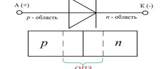
The main structural element is a semiconductor. This is a wafer of silicon or germanium crystal, which has two regions of p and n conductivity. Because of this design feature, it is called planar.
When manufacturing a semiconductor, the crystal is processed as follows: to obtain a p-type surface, it is treated with molten phosphorus, and for a p-type surface, it is treated with boron, indium or aluminum. During heat treatment, diffusion of these materials and the crystal occurs. As a result, a region with a p-n junction is formed between two surfaces with different electrical conductivities. The semiconductor obtained in this way is installed in the housing. This protects the crystal from external influences and promotes heat dissipation.
- Low-current rectifier diodes, they are used in circuits with a current of no more than 0.3 A. The housing of such devices is usually made of plastic. Their distinctive features are light weight and small dimensions.
Low Power Rectifier Diodes - Devices designed for average power can operate with current in the range of 0.3-10 A. Such elements, for the most part, are made of metal housing and equipped with rigid leads. On one of them, namely on the cathode, there is a thread that allows you to securely fix the diode on the radiator used for heat removal.
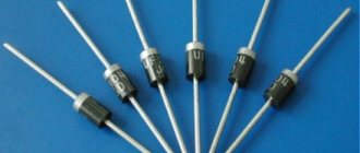
Medium power rectifier diode - Power semiconductor elements, they are designed for direct current over 10 A. Such devices are produced in metal-ceramic or metal-glass housings of the pin type (A in Fig. 4) or tablet type (B).
Rice. 4. High power rectifier diodes
Schottky diode reverse voltage
So, as you remember, a diode allows electric current to pass in only one direction, and in the other direction it blocks the passage of electric current to some critical value, called diode reverse voltage .
This value can be found in the datasheet
diode reverse voltage
It is different for each brand of diode
If this value is exceeded, a breakdown will occur and the diode will fail.
How to calculate a resistor
- find in the documents or measure the voltage of the LED light bulb(s);
- install an LED light bulb and a resistor on the radiators;
- find the polarity of the LED lamp legs;
- connect the battery.
- welding components;
- calculate and buy a resistor (driver);
- make a diagram;
Useful tips Connection diagrams Principles of operation of devices Main concepts Meters from Energomer Precautions Incandescent lamps Video instructions for the master Testing with a multimeter
Voltage drop across a Schottky diode
If you apply direct current to the diode, then the voltage will “settle” on the diode. This voltage drop is called the forward voltage drop of the diode. In datasheets it is designated as Vf, that is, Voltage drop .
forward voltage drop across the diode
If you pass direct current through such a diode, then the power that will be dissipated by it will be determined by the formula:
Where
P—power, W
Vf - forward voltage drop across the diode, V
I is the current through the diode, A
Therefore, one of the main advantages of a Schottky diode is that its forward voltage drop is much lower than that of a simple diode. Consequently, it will dissipate less heat, or in simple terms, heat up less.
Let's look at one example. Let's take a 1N4007 diode. Its forward voltage drop is 0.83 Volts, which is typical for a simple semiconductor diode.
voltage drop across the diode in direct connection
At the moment, a current of 0.5 A is passing through it. Let's calculate its power dissipation at the moment. P=0.83 x 0.5 = 0.415 W.
If we look at this case through a thermal imager, we can see that its body temperature was 54.4 degrees Celsius.
Now let's do the same experiment with a 1N5817 Schottky diode. As you can see, its forward voltage drop was approximately 0.35V.
voltage drop across the Schottky diode when connected directly
When a current of 0.5 A passes through a Schottky diode, we get a power dissipation of P = 0.5 x 0.35 = 0.175 W. At the same time, the thermal imager will show us that the body temperature will already be 38.2 degrees.
Consequently, Schottky is much more efficient than a simple semiconductor diode in terms of passing forward current through itself, since it has a lower voltage drop, and therefore dissipates less heat into the surrounding space and heats up less.
The forward voltage drop can also be viewed in datasheets. For example, the forward voltage drop across a 1N5817 Schottky diode can be found from a graph of forward current versus voltage drop across a Schottky diode
graph of forward current versus voltage
In our case, if we follow the graph-analytical method, we just get a value of 0.35 V
How to calculate a resistor
The amount of resistance is implied by R.
Supply voltage Up.
Drop voltage Udrop.
Flowing current – I.
The constant value of the diode reliability coefficient is 0.75.
For example, we consider a connection to a 12 volt battery. Then it will be:
Using these numbers, you can calculate using a formula that will show that the result is 1.306. Since resistors have a certain pitch, 1.3 kOhm is suitable.
The next task will be to calculate the required minimum resistor power. It is necessary to understand the exact figure of the current passing, because it may not correspond to the above. The calculation can be made using the following formula:
What kind of lighting do you prefer?
Built-in Chandelier
which means that the actual current calculated will be:
To understand the actual voltage drop you need to calculate:
It is better to take power with a small margin. Now it will be just right 0.125 W.
When connecting 1 LED to a 12 volt battery, you will need a resistor in the network, which has a resistance of 1.3 kOhm and a power of 0.125 W.
Schottky diode in RF circuits
Schottky diodes also have fast switching speed. This means we can use them in high frequency (RF) circuits.
So, let's take a frequency generator and set the sine frequency to 60 Hz
Let's take a 1N4007 diode and a 1N5817 Schottky diode. Let's connect them using a simple half-wave rectifier circuit
and we will take evidence from them
As you can see, both of them do an excellent job of rectifying the signal at a frequency of 60 Hz.
But what happens if we increase the frequency to 300 kHz?
Wow! The Schottky diode more or less copes with its task, which cannot be said about a simple 1N4007 diode. A simple diode cannot cope with its task of not allowing reverse current to pass through, so we see a negative surge on the oscillogram
From this we can conclude: Schottky diodes are recommended for use in RF circuits.
Reverse leakage current
But since Schottky diodes are so cool, why not use them everywhere? Why do we still use simple diodes?
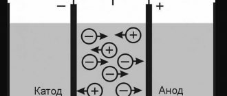
If we connect the diode in the opposite direction, it will block the passage of electric current. This is true, but not entirely. Very little current will still flow through the diode. In some cases this is not taken into account. This small current is called reverse leakage current . In English it sounds like reverse leakage current .
It is very small, but it exists.
Let's do a simple experiment. Let's take a laboratory power supply, set it to 19 V and apply this voltage to the diode in the opposite direction
We measure the leakage current
diode reverse leakage current
As you can see, its value is 0.1 µA.
Let's now repeat the same experiment with a Schottky diode
Schottky diode reverse leakage current
Wow, almost 20 µA already! Well, yes, in some cases these are mere pennies and can be ignored. But there are circuits where such a small current is still unacceptable. For example, in peak detector circuits
peak detector circuit
In this case, these 20 µA will be quite significant.
But there is also another stumbling block. As the temperature increases, the reverse leakage current increases significantly!
dependence of the reverse leakage current on the body temperature of the Schottky diode
Therefore, you cannot use Schottky everywhere in the circuits.
But that's not all. The reverse voltage for Schottky diodes is several times less than for simple rectifier diodes. This can also be seen from the datasheet. If the reverse voltage is 1000V for the 1N4007 diode
Then for a 1N5817 Schottky diode this reverse voltage will already be only 20 V
Therefore, if this voltage exceeds the value described in the datasheet, we will end up with:
List of main characteristics
Below is a table describing the main parameters of rectifier diodes. These characteristics can be obtained from the datasheet (technical description of the element). As a rule, most radio amateurs turn to this information in cases where the element indicated in the diagram is not available, which requires finding a suitable analogue for it.
Table of main characteristics of rectifier diodes
Note that in most cases, if you need to find an analogue of a particular diode, the first five parameters from the table will be quite sufficient. In this case, it is advisable to take into account the operating temperature range of the element and frequency.