In complex electrical circuits, that is, where there are several different branches and several sources of EMF, a complex distribution of currents also occurs. However, with known values of all the emfs and resistances of the resistive elements in the circuit, we can clear the values of these currents and their direction in any circuit circuit using Kirchhoff's first and second laws . I outlined the essence of Kirchhoff’s laws quite briefly in my textbook on electronics, on the pages of the site https://www.sxemotehnika.ru.
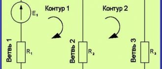
An example of a complex electrical circuit can be seen in Figure 1.
Figure 1. Complex electrical circuit.
Sometimes Kirchhoff's laws are called Kirchhoff's rules , especially in older literature.
So, to begin with, let me remind you of the essence of Kirchhoff’s first and second laws, and then consider examples of calculating currents and voltages in electrical circuits, with practical examples and answers to questions that were asked to me in the comments on the site.
Kirchhoff's first law
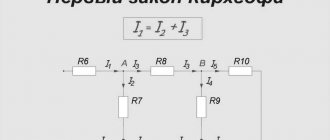
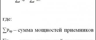
Formulation No. 1: The sum of all currents flowing into a node is equal to the sum of all currents flowing out of the node.
Formulation No. 2: The algebraic sum of all currents in a node is equal to zero.
Let me explain Kirchhoff’s first law using the example of Figure 2.
Figure 2. Electrical circuit assembly.
Here the current I1 is the current flowing into the node, and the currents I2 and I3 are the currents flowing out of the node. Then, using formulation No. 1, we can write:
I1 = I2 + I3 (1)
To confirm the validity of formulation No. 2, we transfer the currents I2 and I 3 to the left side of expression (1) , thereby obtaining:
I1 - I2 - I3 = 0 (2)
The minus signs in expression (2) mean that currents flow out of the node.
The signs for inflowing and outflowing currents can be taken arbitrarily, however, in general, inflowing currents are always taken with a “+” sign, and outflowing currents with a “-” sign (for example, as happened in the expression (2)).
You can watch a separate video lesson on Kirchoff's first law in the VIDEO LESSONS section.
Kirchhoff's laws for calculating electrical circuits
When calculating electrical circuits, including for modeling purposes, Kirchhoff's laws are widely used, which make it possible to fully determine the mode of its operation.
Use the online electrical circuit calculation program. The program allows you to calculate electrical circuits according to Ohm's law, according to Kirchhoff's laws, using the methods of loop currents, node potentials and equivalent generator, as well as calculate the equivalent resistance of the circuit relative to the power source.
Before moving on to Kirchhoff's laws themselves, let us define the branches and nodes of an electrical circuit.
A branch of an electrical circuit is a section of it that consists only of series-connected sources of emf and resistance, along which the same current flows. A node in an electrical circuit is a place (point) where three or more branches connect. By walking along the branches connected at the nodes, you can get a closed circuit of the electrical circuit. Each circuit is a closed path passing along several branches, with each node in the circuit under consideration occurring no more than once [1].
Kirchhoff's first law
Kirchhoff's first law applies to nodes and is formulated as follows: the algebraic sum of the currents in a node is equal to zero:
$$ \sum{i} = 0, $$
or in complex form
$$ \sum{\underline{I}} = 0. $$
Kirchhoff's second law
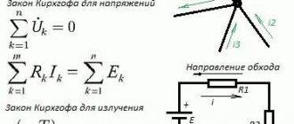
Kirchhoff's second law applies to electrical circuit circuits and is formulated as follows: in any closed circuit, the algebraic sum of the voltages across the resistances included in this circuit is equal to the algebraic sum of the emf:
$$ \sum{\underline{Z} \cdot \underline{I}} = \sum{\underline{E}}. $$
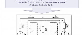
The number of equations compiled for an electrical circuit according to Kirchhoff's first law is equal to $ N_\textrm{y}-1 $, where $ N_\textrm{y} $ is the number of nodes. The number of equations compiled for an electrical circuit according to Kirchhoff’s second law is equal to $ N_\textrm{в}-N_\textrm{у}+1 $, where $ N_\textrm{в} $ is the number of branches. The number of equations to be compiled according to Kirchhoff’s second law can be easily determined by the type of circuit: to do this, it is enough to count the number of “windows” of the circuit, but with one clarification: it should be remembered that the circuit with the current source is not considered .
Let us describe the methodology for composing equations according to Kirchhoff's laws. Let's consider it using the example of an electrical circuit shown in Fig. 1.
Rice. 1. Electrical circuit under consideration
First, you need to arbitrarily the directions of the currents in the branches and set the directions for bypassing the circuits (Fig. 2).
Rice. 2. Setting the direction of currents and the direction of bypassing circuits for an electrical circuit
The number of equations compiled according to Kirchhoff’s first law in this case is equal to 5 – 1 = 4. The number of equations compiled according to Kirchhoff’s second law is 3, although there are 4 “windows” in this case. But let us recall that the “window” containing the source current $ \underline{J}_{1} $ is not considered.
Let's create equations according to Kirchhoff's first law. To do this, we will take the “flowing” currents into the node with a “+” sign, and the “flowing” currents with a “-” sign. Hence for the node “1 y.” the equation according to Kirchhoff's first law will look like this:
$$ \underline{I}_{1}- \underline{I}_{2}- \underline{I}_{3} = 0; $$
for node “2 y.” the equation according to Kirchhoff's first law will look like this:
$$ -\underline{I}_{1}- \underline{I}_{4} + \underline{I}_{6} = 0; $$
for node “3 y.”:
$$ \underline{I}_{2}+ \underline{I}_{4} + \underline{I}_{5}- \underline{I}_{7} = 0; $$
for node “4 y.”:
$$ \underline{I}_{3}- \underline{I}_{5}- \underline{J}_{1} = 0. $$
Equation for the node “5 y.” may not be compiled.
Let's create equations using Kirchhoff's second law. In these equations, positive values for currents and emf are selected if they coincide with the direction of the loop. For the “1 k” circuit the equation according to Kirchhoff's second law will look like this:
$$ \underline{Z}_{C1} \cdot \underline{I}_{1} + R_{2} \cdot \underline{I}_{2}- \underline{Z}_{L1} \cdot \underline{I}_{4} = \underline{E}_{1}; $$
for circuit “2 k.” the equation according to Kirchhoff's second law will look like this:
$$ -R_{2} \cdot \underline{I}_{2} + R_{4} \cdot \underline{I}_{3} + \underline{Z}_{C2} \cdot \underline{I }_{5} = \underline{E}_{2}; $$
for the “3 k” circuit:
$$ \underline{Z}_{L1} \cdot \underline{I}_{4} + (\underline{Z}_{L2} + R_{1}) \cdot \underline{I}_{6} + R_{3} \cdot \underline{I}_{7} = \underline{E}_{3}; $$
where $ \underline{Z}_{C} = -\frac{1}{\omega C} $, $ \underline{Z}_{L} = \omega L $.
Thus, in order to find the required currents, it is necessary to solve the following system of equations:
$$ \begin{cases} \underline{I}_{1}- \underline{I}_{2}- \underline{I}_{3} = 0 \\ -\underline{I}_{1} - \underline{I}_{4} + \underline{I}_{6} = 0 \\ \underline{I}_{2}+ \underline{I}_{4} + \underline{I}_ {5}- \underline{I}_{7} = 0 \\ \underline{I}_{3}- \underline{I}_{5}- \underline{J}_{1} = 0 \\ \underline{Z}_{C1} \cdot \underline{I}_{1} + R_{2} \cdot \underline{I}_{2}- \underline{Z}_{L1} \cdot \underline {I}_{4} = \underline{E}_{1} \\ -R_{2} \cdot \underline{I}_{2} + R_{4} \cdot \underline{I}_{3 } + \underline{Z}_{C2} \cdot \underline{I}_{5} = \underline{E}_{2} \\ \underline{Z}_{L1} \cdot \underline{I} _{4} + (\underline{Z}_{L2} + R_{1}) \cdot \underline{I}_{6} + R_{3} \cdot \underline{I}_{7} = \ underline{E}_{3} \end{cases} $$
In this case, it is a system of 7 equations with 7 unknowns. To solve this system of equations it is convenient to use Matlab. To do this, we present this system of equations in matrix form:
$$ \begin{bmatrix} 1 & -1 & -1 & 0 & 0 & 0 & 0 \\ -1 & 0 & 0 & -1 & 0 & 1 & 0 \\ 0 & 1 & 0 & 1 & 1 & 0 & -1 \\ 0 & 0 & 1 & 0 & -1 & 0 & 0 \\ \underline{Z}_{C1} & R_{2} & 0 & -\underline{Z}_{L1} & 0 & 0 & 0 \\ 0 & -R_{2} & R_{4} & 0 & \underline{Z}_{C2} & 0 & 0 \\ 0 & 0 & 0 & \underline{Z}_ {L1} & 0 & R_{1}+\underline{Z}_{L2} & R_{3} \\ \end{bmatrix} \cdot \begin{bmatrix} \underline{I}_{1} \\ \underline{I}_{2} \\ \underline{I}_{3} \\ \underline{I}_{4} \\ \underline{I}_{5} \\ \underline{I}_ {6} \\ \underline{I}_{7} \\ \end{bmatrix} = \begin{bmatrix} 0 \\ 0 \\ 0 \\ \underline{J}_{1} \\ \underline{ E}_{1} \\ \underline{E}_{2} \\ \underline{E}_{3} \\ \end{bmatrix} $$
To solve this system of equations, we will use the following Matlab script:
>> syms R1 R2 R3 R4 Zc1 Zc2 Zl1 Zl2 J1 E1 E2 E3; >> A = [1 -1 -1 0 0 0 0; -1 0 0 -1 0 1 0; 0 1 0 1 1 0 -1; 0 0 1 0 -1 0 0; Zc1 R2 0 -Zl1 0 0 0; 0 -R2 R4 0 Zc2 0 0; 0 0 0 Zl1 0 (R1+Zl2) R3]; >> b = [0; 0; 0; J1; E1; E2; E3]; >> I = A\b
As a result, we obtain a column vector $ \underline{\bold{I}} $ of currents consisting of seven elements, consisting of the desired currents, written in general form. We see that the Matlab software package allows us to significantly simplify the solution of complex systems of equations compiled according to Kirchhoff’s laws.
List of used literature
- Zeveke G.V., Ionkin P.A., Netushil A.V., Strakhov S.V. Basics of circuit theory. Textbook for universities. Ed. 4th, revised. M., "Energy", 1975.
Recommended Posts
- Loop current method for calculating electrical circuits
When calculating electrical circuits, in addition to Kirchhoff's laws, the loop current method is often used. Loop current method... - Phase coordinate method: example of calculating a transmission matrix Calculation of transmission matrices of multi-terminal networks of various shapes is quite simple. Transfer matrices are a mathematical description of the…
Kirchhoff's second law.
Formulation: The algebraic sum of the EMF acting in a closed circuit is equal to the algebraic sum of the voltage drops across all resistive elements in this circuit.
Here the term “algebraic sum” means that both the magnitude of the EMF and the magnitude of the voltage drop across the elements can be either with a “+” or a “-” sign. In this case, the sign can be determined using the following algorithm:
1. Select the direction of traversing the contour (two options, either clockwise or counterclockwise).
2. We arbitrarily select the direction of currents through the circuit elements.
3. We arrange signs for the EMF and voltages falling on the elements according to the rules:
— EMF that creates a current in the circuit, the direction of which coincides with the direction of bypassing the circuit, is written with a “+” sign, otherwise the EMF is written with a “-” sign.
— voltages falling across the circuit elements are recorded with a “+” sign if the current flowing through these elements coincides in the direction of bypassing the circuit, otherwise the voltages are recorded with a “-” sign.
For example, consider the circuit shown in Figure 3 and write the expression according to Kirchhoff's second law, going around the circuit clockwise and choosing the direction of the currents through the resistors, as shown in the figure.
Figure 3. Electric circuit to explain Kirchhoff's second law.
E1- E2 = -UR1 - UR2 or E1 = E2 - UR1 - UR2 (3)
I suggest watching a separate video lesson on Kirchoff's second law (theory).
Direct current: Kirchhoff's laws
When solving problems using Kirchhoff's laws, it is better to adhere to a certain algorithm: 1. determine the number of unknown currents - how many equations should be in the system; 2. determine the number of nodes - equations according to the first law, then you need to create one less; 3. draw contours and write equations for them according to the second law. For those who want to understand it thoroughly, there is a video.
Task 1. Two elements with B and B are connected according to the circuit shown in the figure. Ohm resistance. The internal resistance of the elements is the same Ohm. Determine the current flowing through the resistance.
To task 1
Let us designate the currents in the branches arbitrarily. According to Kirchhoff's first law, the sum of the currents converging at a node is equal to 0:
We will go around the upper contour counterclockwise. According to Kirchhoff’s second law, the sum of the voltage drops in the circuit is equal to the sum of the emf:
We will go around the second circuit clockwise:
There are three unknown currents, we have compiled three equations. This is enough to find the currents:
Let us express from the second equation, and from the third:
Let's substitute these expressions into the first equation:
Then the currents and
Answer: A, A, A. Task 2. Find the current strength in all sections of the circuit if V, V, V, Ohm, Ohm, Ohm, Ohm, Ohm, Ohm.
To task 2
We designate the currents in the branches arbitrarily, select the directions of circuit bypasses and the circuits themselves. We compose a system of equations. First, let's create an equation according to Kirchhoff's first law - we have two nodes, so there will be one equation.
Then, bypassing the contours, we will compose two equations according to the second law: there are two of them that need to be composed, since there are three unknown currents in the circuit.
We solve the system and find the answer (I solved it using an online calculator): , , .
Answer: , , .
Task 3. In the circuit shown in the figure, find the current through the galvanometer, if V, kOhm; V, kOhm. Neglect the resistance of the galvanometer.
To problem 3
We don’t know the resistance of the galvanometer; let’s write two equations for the voltage across it:
Equating, we get
Note that if , then the equality will be satisfied. Thus, no current flows through the galvanometer.
Answer: .
Problem 4. In the circuit V‚ V, Ohm, Ohm. Find the distribution of currents in the circuit. Do not take into account the internal resistance of current sources.
To problem 4
We designate the currents in the branches arbitrarily, select the directions of circuit bypasses and the circuits themselves. We compose a system of equations. First, let's create an equation according to Kirchhoff's first law - we have three nodes, so there will be two equations. Then, bypassing the contours, we will compose three equations according to the second law: there are exactly three of them that need to be composed, since there are six unknown currents in the circuit.
We solve the system and find the answer (I solved it using an online calculator): , , , , , .
Answer: , , , , , . Problem 5. What current strength will the ammeter show in the circuit shown in the figure? Neglect the resistance of the ammeter.
To problem 5
Let us designate the currents in the circuit arbitrarily. Let us denote the directions for traversing the contours. Let's write a system of equations: we will compose three equations according to the first law (one less than the number of nodes) and three equations according to the second law, since there are six unknown currents and the system should consist of six equations.
To use the calculator, I entered Ohm and V. The result was: , , , , , .
The minuses indicate the opposite direction of the current in this branch to what we drew.