Today we are interested in the simplest oscillatory circuit , its operating principle and application.
For useful information on other topics, go to our Telegram channel.
Oscillations are a process that repeats over time and is characterized by changes in system parameters around the equilibrium point.
The first thing that comes to mind is the mechanical vibrations of a mathematical or spring pendulum. But vibrations can also be electromagnetic.
By definition, an oscillatory circuit (or LC circuit) is an electrical circuit in which free electromagnetic oscillations occur.
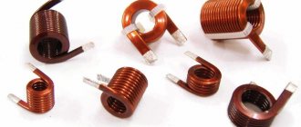
Such a circuit is an electrical circuit consisting of a coil with inductance L and a capacitor with capacitance C. These two elements can be connected in only two ways - in series and in parallel. Let us show in the figure below an image and a diagram of a simple oscillatory circuit.
By the way! For all our readers there is now a 10% on any type of work .
By the way! For all our readers there is now a 10% on any type of work .
Operating principle of the oscillating circuit
Let's look at an example where we first charge the capacitor and complete the circuit. After this, a sinusoidal electric current begins to flow in the circuit. The capacitor is discharged through the coil. In a coil, when current flows through it, a self-inductive emf , directed in the direction opposite to the capacitor current.
Having completely discharged, the capacitor, thanks to the energy of the EMF of the coil, which at this moment will be maximum, will begin to charge again, but only in reverse polarity.
The oscillations that occur in the circuit are free damped oscillations. That is, without additional energy supply, oscillations in any real oscillatory circuit will sooner or later stop, like any oscillations in nature.
This is due to the fact that the circuit consists of real materials (capacitor, coil, wires) that have such a property as electrical resistance, and energy losses in a real oscillatory circuit are inevitable. Otherwise, this simple device could become a perpetual motion machine, the existence of which, as we know, is impossible.
Another important characteristic of an LC circuit is the quality factor Q. The quality factor determines the amplitude of the resonance and shows how many times the energy reserves in the circuit exceed the energy losses during one oscillation period. The higher the quality factor of the system, the slower the oscillations will decay.
Resonance of currents in a parallel oscillatory circuit
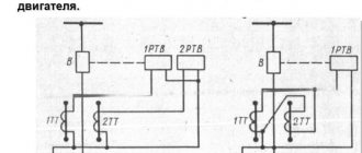
Let's consider the case of parallel connection of an oscillating circuit with a current source (Fig. 1) and see what the circuit resistance will be for currents of different frequencies in this case. If the frequency of the current is low (below resonant), then almost all of the current will flow along the easiest path for it - through the inductive branch; The circuit resistance at low frequencies will be small in magnitude and inductive in nature.
For currents of high frequencies (above resonant), the easier path will be through the capacitive branch, and, therefore, the circuit resistance will also be small in magnitude, but capacitive in nature.
At the resonant frequency, when the capacitive reactance is equal to the inductive reactance, the path for the current will be equally difficult through both branches. We know that when two equal resistances are connected in parallel, the total resistance is equal to half of either one. Therefore, it would seem that the circuit resistance at resonance should be equal to half of one of the reactances. However, we should not forget that we are dealing with resistances, although identical in magnitude, but having a fundamentally different character. This difference is manifested in the fact that the currents in the inductive and capacitive branches of the circuit are shifted in phase relative to each other by 180°. It immediately follows that in the unbranched part of the circuit, not the total, but the difference current always flows (Fig. 1).
Figure 1. Currents at parallel resonance. In the unbranched part of the circuit, it is not the residual current that flows, but the difference current.
Therefore, at resonance, when the currents in the capacitive and inductive branches are equal to each other, the current in the unbranched part of the circuit will be zero, no matter what voltage we apply to the circuit. With resonance between the points AB, the circuit will seem to be broken, that is, its resistance between these points will be infinitely large, and will not at all be equal to half of one of the reactances. There is no practically infinitely large circuit resistance at resonance, since due to the presence of active resistance in the circuit (resistance of the coil wire), the phase shift of the currents can never be exactly 180°.
However, the active resistance of the coil is usually much less than its inductive resistance, and therefore the resistance of the oscillating circuit at resonance can reach very large values.
The resistance of the oscillatory circuit at parallel resonance is equal to:
where L is expressed in g, C is in f, RL is in ohm.
The impedance of the oscillatory circuit at resonance is purely active due to the fact that the inductive and capacitive reactances are mutually compensated.
The curves of changes in the impedance of the oscillatory circuit between points AB with a change in the frequency of the current are shown in Fig. 2, b.
Figure 2. Resonance of currents. a) — diagram and designations; b) - graph of total resistance.
With parallel resonance, the currents in the branches of the circuit reach their greatest value; therefore parallel resonance is called current resonance.
The phenomenon of resonance is of great importance in radio engineering. There are a large number of transmitting radio stations around the globe. The broadcasts of all these radio stations are distributed throughout the airwaves and are all simultaneously received by the receiving antenna. It’s not difficult to imagine how a pile of programs would turn out if we couldn’t single out from this chaos only the one we need. This is where the phenomenon of resonance comes to the rescue. Transmitting radio stations emit electromagnetic energy into space at various frequencies, but we, by tuning the circuits of our receiver in resonance with a particular frequency, thereby select the transmission we need.
DID YOU LIKE THE ARTICLE? SHARE WITH YOUR FRIENDS ON SOCIAL NETWORKS!
Related materials:
- Coil inductive reactance
- Inductor in an AC circuit
- Capacitor in an alternating current circuit. Capacitance of a capacitor.
- AC circuit resistance
- AC circuit impedance
- Resonance phenomenon
- Ohm's law for alternating current
- Voltage resonance in a series oscillating circuit
- Pulsating current
- Non-sinusoidal current
Add a comment
LC circuit resonance
Electromagnetic oscillations in an LC circuit occur at a certain frequency, which is called resonant. More details about resonance can be found in our separate article. The oscillation frequency can be changed by varying circuit parameters such as capacitor capacitance C , coil inductance L , resistor resistance R (for LCR circuit ).
How to calculate the resonant frequency of an oscillating circuit? Very simple! Here is the final formula:
Parallel circuit
In Fig. 101, and an oscillatory circuit with elements L and C connected in parallel is presented in relation to the applied e. d.s. ( parallel circuit
). If its frequency coincides with the frequency of free oscillations of the circuit, then resonance of currents occurs.
| In this case, as can be seen from the vector diagram (Fig. 101,b), the currents in both branches of the circuit are equal to each other, since the impedances of the inductive (Z1) and capacitive (Z2) branches are equal to each other. But this creates phase shifts between the currents and relative to the applied e. d.s. Rice. 101. Forced oscillations in a circuit with elements connected in parallel: a - connection circuit; b - vector diagram (resonance of currents); c - dependence of the circuit resistance and current in the supply wire on frequency. |
It also follows from the vector diagram that the current I in the unbranched part of the circuit is minimal at resonance, and therefore the resistance is maximum and active (the current vector I and the emf vector E are in phase). The resistance equivalent to the circuit at resonance is
where r1, r2 are the active resistances of the corresponding branches of the circuit; X is the reactance of any of them; R is the total active loss resistance.
If X1 and X2 are replaced with their values, then we can obtain a formula that establishes the relationship between the circuit resistance at resonance and the circuit elements:
(155)
It should be noted that the equality of the reactances of both branches of the circuit is a sufficient condition for determining the resonant frequency ƒ0=1/2π√LC only if the active losses in the branches of the circuit are equal. If the active losses in the circuit branches are not the same, then the resonant frequency determined by the above formula must be adjusted, i.e., the circuit must be adjusted.
Expressing the inductance of the coil in microhenry, the frequency in megahertz, and the capacitance of the circuit in picofarads, we obtain a formula that establishes the relationship between these quantities in the following form:
The definition of quality factor given earlier for a series circuit is not suitable here, since the voltage on the circuit elements, regardless of its settings, is equal to Uk (see Fig. 101, a). Physical meaning of the quality factor for a parallel oscillatory circuit
can be obtained by equating the following expressions that determine the voltage on the circuit:
Uк = IRE = Iкρ
where
(156)
The quality factor Q shows how many times the current in the circuit at resonance is greater than the current in an unbranched circuit.
At frequencies below the resonant one, the resistance of the inductive branch is less than the resistance of the capacitive branch of the circuit and, therefore, the current in the inductive branch becomes greater than the current in the capacitive branch. Therefore, the circuit at frequencies below the resonant one, relative to the source of e. d.s, is an inductive load.
At frequencies above the resonant one, the pattern becomes opposite and the parallel oscillating circuit behaves like a capacitive load.
| Parallel oscillatory circuit usually included in the anode circuit of the lamp. When analyzing such a circuit, the lamp is replaced by an equivalent alternating current generator with e. d. s equal to μUс (where Uс is the input signal voltage on the control grid of the lamp), with internal resistance Ri (Fig. 102, a). Depending on the ratio of the resistance values Ri and Re at resonance, one can judge whether the circuit is tuned to resonance either by the behavior of the current in an unbranched circuit or by the behavior of the voltage at the circuit terminals. Rice. 102. Setting up a parallel circuit: a - equivalent circuit for connecting the circuit to the anode circuit of an electron tube; b - graph of I and Uк= φ (ƒ) at Ri<е; c - graph of I and Uк = φ (ƒ) at Ri<е; d - graph of I and Uк = φ (ƒ) at Ri<е. |
The current in an unbranched circuit is equal to
Circuit terminal voltage
Uк= I Re
If Ri<< Re (which occurs when the circuit is connected to the anode circuit), then when setting up the circuit, at the moment of resonance, the current in the supply wire will be minimal, and the voltage at the circuit terminals will change slightly. Since, as the circuit approaches resonance, the resistance of the circuit increases, and the current in the unbranched circuit decreases, the product of these quantities, which represents the voltage on the circuit, remains almost unchanged. Thus, in the case under consideration, it is possible to judge whether the circuit is tuned to resonance only by the minimum current in the supply wire (Fig. 102, b).
If Ri >> Re then, reasoning in a similar way, it is easy to come to the conclusion that when adjusting the circuit, the current in the supply wire remains almost unchanged. Consequently, whether the circuit is tuned to resonance can be judged only by the behavior of the voltage at the circuit terminals (Fig. 102, c).
Of particular interest is the third case, when Ri and Re are commensurable, i.e. Ri≈ Re. In this case, the adjustment of the circuit to resonance can be judged both by the behavior of the voltage at the circuit terminals and by the behavior of the current in an unbranched circuit (Fig. 102, d).
Parallel Circuit Bandwidth
the current can be determined by formula (153) for the passband of a series circuit only at Ri = 0. The same conclusion can be reached when determining the voltage passband at Ri = ∞:
2∆ƒ1 = ƒ0/Q at Ri = 0; 2∆ƒU = ƒ0/Q at Ri→∞.
At Ri = Re the current and voltage bandwidths can be determined by the formulas
The voltage bandwidth is wider than the current bandwidth. This is explained by the fact that the internal resistance of the generator shunts the circuit, i.e., it seems to increase losses in it. Therefore, sometimes, to expand the bandwidth of the circuit, it is specially shunted with resistance. Additional losses ∆r introduced into the circuit are determined by the formula
(157)
where X is the reactance of the circuit branch; Rsh - shunt resistance. The quality factor of the circuit, taking into account the influence of the shunt resistance, is determined by the formula
It is known that the greatest current in an electrical circuit occurs when the internal resistance of the source and the load resistance are equal, therefore, when considering the equivalent circuit shown in Fig. 102a, we can also conclude that the maximum current in the circuit, and therefore the maximum voltage at the circuit terminals and the maximum power in the circuit, will be released at Ri = Re. This means that the oscillatory circuit included in the anode circuit of the lamp must not only be tuned to the signal frequency, but also represent a resistance that ensures the most appropriate mode of operation of the vacuum tube.
In this regard, in contrast to the contour presented in Fig. 102, a, called a circuit of the first type, uses oscillatory circuits in which inductances or capacitances are distributed between the branches of the circuit. They are called contours of the second and third types, respectively (Fig. 103, a, b). The circuit setting will not change with any redistribution of elements L and C between the branches of the circuit, provided that the full values of these quantities remain unchanged.
| So, for example, if the capacitance of the circuit capacitor was 100 pF, then the circuit setting will not change if this capacitance is replaced by two capacitors with a capacity of 200 pf each connected in series to the circuit. Rice. 103. Oscillatory circuits of the second (a) and third (b) types. |
The situation is different with the resistance of the circuits of the second and third types at resonance.
Let's consider a circuit of the second type, in which the inductance L is distributed between the branches of the circuit. The resistance of the parallel circuit at resonance, according to definition, is equal to X21.2/R. In our case, X1 = ω0L1, and not ω0L = ω0 (L1 + L2), as was the case in the first type of circuit. Therefore, the circuit resistance of the second type at resonance
Multiply the numerator and denominator by L, then
(158)
The switching factor or coefficient that takes into account the distribution of inductance L between the branches of the circuit, p = L1/L<1, therefore, the resistance of the second type of circuit at resonance is less than the resistance of the first type of circuit.
A similar conclusion can be reached when considering a circuit of the third type, the resistance of which at resonance
Re III=q2Re (159)
where q=С/С1<1 (since С=C1C2/C1+C2)
Thus, by redistributing inductance or capacitance between the branches of the circuit, it is possible to transition from a circuit of one type to a circuit of another type. This transition allows you to keep the setting unchanged, change the circuit resistance at resonance and thereby ensure its coordination (equality) with the internal resistance of the vacuum tube.
Series circuit
A series oscillatory circuit is characterized by the presence of a series connection of a capacitance with an inductance. Moreover, these two elements do not affect energy losses in the circuit and are ideal elements.
Losses in this circuit are caused only by the presence of an active load. Below is a graph of the amplitude-frequency response of such a circuit.
For such a circuit, the resistance of the coil and capacitor are parasitic and lead to resonance. This resonance equalizes or nullifies the resistance, leaving only the influence of the active load R from the resistor. In this case, the quality factor of such an electrical circuit is determined as the difference in voltages at the current source and the outputs of the coil/capacitor. In this case, Q is determined using the following expression:
In this formula:
- C is the capacitance of the capacitor.
- L is the inductance of the coil.
- R is resistance loss.
For example, let's try to solve the following problem. The circuit contains an inductor L=100 mH with a resistance R=100 Ohm, which is connected in series with a capacitor with a capacitance C=0.07 μF. Find the resonant frequency ω0, the characteristic impedance and the quality factor of the oscillatory circuit.
We calculate the resonant frequency of the circuit:
We determine the characteristic resistance:
The final step is to calculate the quality factor of the circuit: