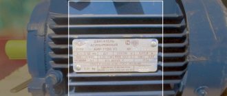
The creation of a three-phase asynchronous electric motor occurred at the end of the 19th century. Since then, no industrial work has been possible without its use. The most significant moment in the work process is the smooth starting and braking of the engine. This requirement is fully met with the help of a frequency converter.
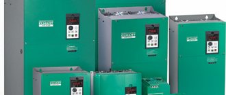
There are several options for the names of the frequency generator for a three-phase electric motor. In particular, it may be called:
- Inverter;
- AC frequency converter;
- Frequency converter;
- Variable frequency drive.
An inverter is used to regulate the rotational speed of an asynchronous electric motor designed to convert electrical energy into mechanical energy. The movement carried out in this case can be transformed into a movement of another type.
A specially designed frequency converter circuit allows the engine efficiency to be increased to a level of 98%.
The most significant use of a converter is in the design of a high-power electric motor. The frequency converter allows you to change the starting currents and set the required value for them.
Operating principle of frequency converter
Using manual control of the starting current is fraught with unnecessary energy consumption and a reduction in the service life of the electric motor. In the absence of a converter, the rated voltage value is also exceeded several times. Due to working in this mode, there is also a negative impact.
In addition, the frequency converter ensures smooth control of the motor operation, focusing on balancing voltage and frequency values, and reduces energy consumption by half.
The entire list of positive aspects is possible thanks to the principle of double voltage conversion. It works as follows:
- The mains voltage is regulated through rectification and filtering in the direct current link.
- Performing electronic control, which generates a certain frequency, in accordance with a pre-designated mode, and three-phase voltage.
- Rectangular pulses are produced, followed by amplitude adjustment using the stator winding.
conclusions
Asynchronous electric motors are superior to DC motors in many respects. This superiority concerns both the device and reliability. Therefore, in many cases, users choose asynchronous motors, guided precisely by considerations of their superiority over other devices.
Mechanical current control causes some negative consequences, since when using this control option one cannot be sure of one hundred percent and high-quality operation of the equipment. The use of frequency converters for asynchronous motors has its very important advantages, which are important in many aspects of working with motors. One of the most important advantages of using electronic control and frequency converters is the fact that these devices allow you to save energy consumption. In addition, the power will be greater.
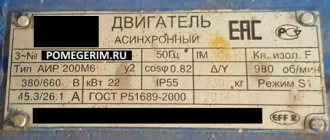
Frequency drivers should be selected taking into account many characteristics that are specified in the documentation attached to the device. Home-made frequency converters can be useful in domestic conditions, but they should not be used in production.
The operation of converters must be carried out correctly, in accordance with all recommendations and rules. This will improve the quality of equipment operation. In addition, many tips will extend the life of the engine and converter. It is highly recommended to monitor the voltage. In the event of a critical increase in voltage, capacitors may explode. Frequency generators must be used in compliance with all basic safety rules. It is recommended not to start working with them without all the necessary knowledge in this area.
Useful tips Connection diagrams Principles of operation of devices Main concepts Meters from Energomer Precautions Incandescent lamps Video instructions for the master Testing with a multimeter
How to choose the right frequency converter
The most important thing when buying a frequency generator is not to spare money. In the case of a converter, cheap always means little functionality, which makes the purchase useless.
You should also pay attention to the type of control of the converter:
- Vector.
High-precision current setting.
- Scalar.
The operating mode is limited by the specified output frequency and voltage ratio. This type of control is only suitable for simple household appliances.
Next, you should pay attention to the power of the frequency converter. It's simple: the more, the better.
The supply network must provide a sufficiently wide voltage range. This reduces the risk of breakage during sudden surges. Excessively high voltage can cause capacitors to explode.
Frequency indicators must meet production needs. Their lower threshold determines the breadth of possibilities for controlling the drive speed. The maximum frequency range is only possible with vector control.
The number of incoming/outgoing control connectors should be slightly greater than the minimum required. But this, of course, is reflected in an increase in price and difficulties in installing the device.
Finally, you need to pay attention to the coincidence of the characteristics of the control bus and the parameters of the frequency converter. This is determined by the corresponding number of connectors.
It is important to note the ability to withstand overloads. The power reserve of the frequency converter should be 15% greater than the motor power.
Frequency selection
Manufacturers of such devices focus on the cost of frequency converters. It follows from this that many of the options that are available on more expensive models will no longer be present on cheap converter models. Before choosing the right device, you should pay attention to the technical characteristics of all available models presented in the range, as well as the basic requirements for a specific use.
- Control can be carried out in two ways : vector and scalar. Vector control allows precise adjustment. The principle of operation of scalar control is to maintain one relationship between voltage and frequency at the output, specified by the user. Scalar control is not suitable for complex devices and is used on simpler devices such as a fan.
- The higher the power indicated in the characteristics , the higher the versatility of the converter. This means that it will ensure interchangeability. In addition, maintenance of such a device will be easier.
- You should definitely pay attention to the specified mains voltage range . It should be as wide as possible, which will ensure safety when its standards change. And we cannot fail to mention the fact that an increase is much more dangerous than a decrease. When increased, the network capacitors may explode.
- The specified frequency must necessarily correspond to all production needs . The drive speed control range is indicated by the lower limit. If you need a broader one, you should resort to vector control. Practical application involves the use of frequencies such as: from 10 to 60 Hz. Rarely, but occur up to 100 Hz.
- The implementation of control involves the use of various inputs and outputs . The more there are, the better, of course. But you need to take into account that with a larger number of inputs and outputs, the cost of the frequency converter significantly increases, and its configuration also becomes more complicated.
- Attention should also be paid to the control bus of the connected equipment . It must match the capacity of the frequency generator circuit in terms of the number of inputs and outputs. Also, do not forget that it is better to have a small smell available for possible modernization.
- Don't forget about the device's overload capabilities . It is recommended to select a frequency converter with a power that is 15% greater than the power of the motor used. It is strongly recommended that you read the instructions included with the frequency converter. Manufacturers certainly indicate all its main parameters in the documentation for the device. If peak loads are important, then when choosing a device, you should pay attention to the actual current indicators and the values indicated as peak. In this case, you need to select a converter with peak current ratings that will be 10% higher than those indicated in the documentation.
Self-connection of the converter
Before you start connecting the device, you should use a de-energizing circuit breaker; it will ensure that the entire system is turned off in the event of a short circuit to any of the phases.
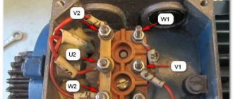
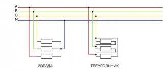
There are two schemes for connecting an electric motor to a frequency converter:
- "Triangle".
The diagram is relevant if you need to control a single-phase drive. The power level of the converter in the circuit is up to three kilowatts, and no power is lost.
- "Star".
A method suitable for connecting the terminals of three-phase frequency drives powered by industrial three-phase networks.
The figure shows the connection diagram for the 8400 Vector.
To limit the starting current and reduce the starting torque when starting an electric motor with a power exceeding 5 kW, star-delta switching is used.
When voltage is applied to the stator, the device is connected as a star. As soon as the motor speed begins to correspond to the nominal value, power is supplied according to the “triangle” circuit. But this technique is used only when technical capabilities allow connecting in two circuits.
In a combined star and delta circuit, sharp current surges are observed. When switching to the second type of connection, the rotational speed readings decrease significantly. To restore the previous operating mode and speed, the current should be increased.
Frequency generators are most actively used in the design of an electric motor with a power level of 0.4 - 7.5 kW.
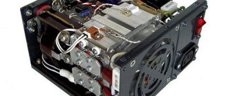
Components of a state of emergency
Control board
The control board contains a microcontroller and galvanically isolated external interfaces:
- interface for connecting an external quadrature encoder
- RS232 interface
- CAN interface
- USB interface
- three digital outputs and one digital input
The control board is connected to the power board via two flat cables via connectors X7 and X8. The gate control signals of the IGBT module pass through X7. X8 carries current and voltage measurement signals, I2C lines, and several other signals. A similar scheme is used in Goodrive20-EU.
Sheet 1 of the control board diagram
Sheet 2 of the control board diagram
3D model of the control board
In addition, the control board contains a lithium battery to support the non-volatile operation of the real-time clock, a holder for a uSD card and a buzzer. These are not required components, but useful at the stage of software development, debugging and diagnostics.
DC bus board
The DC bus is at a voltage of 310…340 V and an average current of up to 10A passes through it at maximum power. The board contains a power supply in the form of a separate module. It was decided to make the power supply this way simply to simplify the board design. On the board there is a transistor switch Q3 that controls the fans. The fans turn on only when the IGBT module reaches a certain set temperature.
DC bus and power board
How to connect a three-phase motor to a 220 V network
The use of a three-pole AD in a single-phase electrical network is of interest to many owners of private houses. The units are increasingly in demand in households. They are quite simple in design and easy to use. However, in terms of connecting the motor to a single-phase network, not everything is so simple.
The pulsating field of a single-phase current is not capable of causing the rotor of an electric motor to rotate - such a current must be converted into multiphase and then only supplied to the unit.
Add a link to a discussion of the article on the forum
RadioKot >Schemes >Power >Converters and UPS >
| Article tags: | Add a tag |
A simple frequency converter for an asynchronous electric motor.
Author: Sergey M. Published 12/11/2012 Created with the help of KotoEd.
The first was a restaurant - in winter, cold air should be blown in strictly measured doses on overheated visitors, and in summer, on the contrary, those frozen from cold ice cream should be gradually warmed by hot air from the street. There is no way to do without an inverter. The second one wants to shear shaggy sheep, but the problem is that the machine is three-phase. And there is only one in the field, and even that one is not 220V. We need an inverter again. The third one is an emery stone, a drilling machine and a winding machine - I wanted to attach it to the engine. In the end, looking around, I saw that everything... everything is made by Japanese, French, German inverters... , but I don’t have my own screwdriver sharpener yet. And what’s more, all the decent companies have already written how to do this.
So, since the asynchronous motor is so widespread and the three-phase voltage system created by M. O. Dolivo-Dobrovolsky is so convenient. And the modern element base is so good. Then making a frequency converter is just a matter of personal desire and some financial capabilities. Perhaps someone will say, “Well, why do I need an inverter? I’ll install a phase-shifting capacitor and everything is decided.” But at the same time you can’t turn the speed and you’ll lose power and then it’s not interesting.
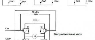
Let's take it as a basis - in everyday life there is a single-phase 220V network, the popular motor size is up to 1 kW. This means we connect the motor windings with a triangle. Further – it’s simpler, you will need a three-phase bridge driver IR2135 (IR2133), we choose this one because it is used in industrial equipment, it has an SD output and a convenient pin arrangement. IR2132 is also suitable, but it has a longer dead time and does not have an SD output. As a PWM generator, we will choose the AT90SPWM3B microcontroller - it is accessible, understandable to everyone, has a lot of capabilities and is inexpensive, there is a simple programmer - https://real.kiev.ua/avreal/. We will select 6 power transistors IRG4BC30W with some current reserve - the starting currents of the IM can exceed the rated ones by 5-6 times. And for now we don’t install a “brake” key and a resistor, we will brake and magnetize the rotor with direct current before starting, but more on that later... The entire work process is displayed on a 2-line LCD indicator. For control, 6 buttons are enough (frequency +, frequency -, start, stop, reverse, menu). The result is this diagram.
I do not at all claim that the design is complete and I propose to take this design as a kind of basis for home electric drive enthusiasts. The boards shown here were made to fit the parts at my disposal. Structurally, the inverter is made on two boards - the power part (power supply, driver and bridge transistors, power terminals) and the digital part (microcontroller + indicator). The boards are electrically connected by a flexible cable. This design is chosen for future migration to a TMS320 or STM32 or STM8 controller. The power supply is assembled according to a classic design and does not need any comments. IL300 linear opto-isolation microcircuit for controlling current 4-20Ma. Optocouplers OS2-4 simply duplicate the “start, stop, reverse” buttons for galvanically isolated control. Optocoupler output OS-1 “user function” (alarm, etc.) Power transistors and a diode bridge are mounted on a common radiator. Shunt 4 turns of manganin wire with a diameter of 0.5 mm on a 3 mm mandrel. Let me immediately note that some nodes and elements are not at all necessary. In order to simply turn the motor, you do not need external current control of 4-20 Ma. There is no need for a current transformer; a current shunt is also suitable for evaluation measurements. No external alarm required. With a motor power of 400 W and a radiator area of 100 cm2, there is no need for a temperature sensor.
IMPORTANT! – the control buttons on the board are isolated from the power supply only by plastic pushers. For safe control it is necessary to use optical isolation.
Possible changes in the circuit depending on the firmware. The DA-1 amplifier can be connected to a current transformer or to a shunt. The DA-1-2 amplifier can be used to measure network voltage or to measure the resistance of a thermistor if the PD-1 temperature sensor is not used. In the case of long connecting wires, it is necessary to at least put an interference suppression ring on each wire. There is interference. For example, until I did this, my mouse froze. I also think it is important to note the reliability of the insulation of the blood pressure because... When switching power transistors, voltage surges on the windings can reach values of 1.3 Upit. General form.
A little about management.
Having read books with long formulas mainly describing how to make a sine wave using PWM. And how to stabilize the rotation speed of the motor shaft using a tachometer and PID controller. I came to the conclusion that the AD has a fairly rigid characteristic over the entire range of permissible loads on the shaft. Therefore, for personal needs, the management described by the law of M.P. Kostenko or as it is also called scalar. Sufficient for most practical cases of using a variable frequency electric drive with an engine speed control range of up to 1:40. Those. Roughly speaking, in the simplest case we make an ordinary 3-phase socket with variable frequency and voltage changing in direct proportion. With small “buts”, in the initial sections of the characteristic it is necessary to perform IR compensation, i.e. at low frequencies you need a fixed voltage. Three times “but” to mix the 3rd harmonic into the voltage supplying the engine. The physical principles of AD will do the rest for us. You can read more about this in the document AVR494.PDF Based on my personal observations and modest experience, these methods are most often used without any special frills in drives with power up to 15 kW. Further I will not delve into the theory and description of mathematical models of blood pressure. Even without me, professors outlined this quite well back in the 60s. But in no case should you underestimate the complexity of blood pressure management. All my simplifications are justified only by the non-commercial use of the inverter. Board of power elements.
The V-1.0 program for AT90SPWM3B implements 1-Frequency IM control. Voltage waveform is a sinusoid with the 3rd harmonic. 2- Reference frequency 5 Hz -50 Hz in 1 Hz steps. PWM frequency 4 kHz. 3- Fixed acceleration-deceleration time 4- Reverse (only through the STOP button) 5- Acceleration to a given frequency in steps of 1 Hz 6 – Indication of ADC channel readings 6 (8 bits, window filter aperture 4 bits) I use this channel for shunt current measurement. 7 – Indication of operating mode START, STOP, RUN, RAMP, and Frequency in Hz. 8- Processing the alarm signal from ms IR2135
Engine braking is forced - without coasting. At the same time, you need to remember that if a huge fan or flywheel hangs on the shaft, the voltage on the DC link can reach dangerous values. But I think no one will build helicopters powered by IM.
Firmware features in future versions
1 - magnetization of the rotor before starting 2 - DC braking 3 - direct reverse 4 - reference frequency 1 -400 Hz. 5 – limitation, motor current control. 6 - switchable U/F dependencies 7 - DC link control. 8 – some control macros are generally in the distant future.
Tests. This design has been tested with a 0.18kW and 0.4kW and 0.8kW motor. All engines were satisfied. Only at low speeds and long-term operation is forced cooling of the IM necessary.
Line for the programmer av_28r4.exe -aft2232 -az +90pwm3b -e -w -v -fckdiv=1,psc2rb=0,psc1rb=0,psc0rb=0,pscrv=0,bodlevel=5 -c01.hex A little “evening” test video
Files:
microcontroller board -layout5.0 power module -layout5.0 Program for MK circuit S_plan7 -rar archive
All questions in the Forum.
| What do you think of this article? | Did this device work for you? | |
| 56 | 6 | 2 |
| 0 | 0 |
Use a voltage converter (inverter)
The easiest way to make 380 Volts is to purchase and install a three-phase voltage converter (inverter). A single-phase voltage of 220V is supplied to the input of this device, and three phases of 380V appear at the output terminals of the device. This is the best, although the most expensive, method of obtaining three-phase power.
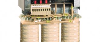
Structurally, the inverter consists of four units - a rectifier and three converters that convert 220 V DC into AC. Due to the appropriate settings and connections of the nodes, the individual phases are shifted by 120°, which ultimately gives a linear voltage of 380 V.
Most inverters have a built-in voltage stabilizer and various types of protection that turn off the power in case of overload, short circuit or high input voltage.