Electric motor power calculation
Electric motor power by current can be calculated using our online calculator:
The result can be rounded to the nearest standard power value.
Standard values of electric motor power : 0.25; 0.37; 0.55; 0.75; 1.1; 1.5; 2.2; 3.0; 4.0; 5.5; 7.5; eleven; 15; 18.5; 22; thirty; 37; 45; 55; 75 kW, etc.
Engine power is calculated using the following formula:
- U - Rated voltage (voltage to which the electric motor is connected);
- I - Rated current of the electric motor (taken from the passport data of the electric motor , and in their absence is determined by calculation);
- cosφ - Power factor - the ratio of active power to total power (taken from 0.75 to 0.9 depending on the power of the electric motor);
- η - Efficiency factor - the ratio of the electrical power consumed by the electric motor from the network to the mechanical power on the motor shaft (taken from 0.7 to 0.85 depending on the power of the electric motor);
Motor current calculation
The rated and starting current of an electric motor can be calculated by power using our online calculator:
The rated motor current is calculated using the following formula:
- P - Rated power of the electric motor (taken from the motor’s passport data or determined by calculation);
- U - Rated voltage (voltage to which the electric motor is connected);
- cosφ - Power factor - the ratio of active power to total power (taken from 0.75 to 0.9 depending on the power of the electric motor);
- η - Efficiency factor - the ratio of the electrical power consumed by the electric motor from the network to the mechanical power on the motor shaft (taken from 0.7 to 0.85 depending on the power of the electric motor);
The starting current of the electric motor is calculated using the formula:
- K - Starting current multiplicity, this value is taken from the electric motor passport, or from catalog data (in the above online calculator, the starting current multiplicity is determined approximately based on the other specified characteristics of the electric motor).
Calculation of electric motor power factor
Online calculation of power factor (cosφ) of an electric motor
Calculation of cosφ (cosine phi) of the engine is carried out using the following formula:
- P - Rated power of the electric motor (taken from the motor’s passport data or determined by calculation);
- U - Rated voltage (voltage to which the electric motor is connected);
- I - Rated current of the electric motor (taken from the passport data of the electric motor , and in their absence is determined by calculation);
- η - Efficiency factor - the ratio of the electrical power consumed by the electric motor from the network to the mechanical power on the motor shaft (taken from 0.7 to 0.85 depending on the power of the electric motor);
Calculation and selection of starting and protective equipment
When choosing magnetic starters (Figure 4), it is necessary to take into account the operating mode, which is determined by the nature of the switched load:
Expert opinion
It-Technology, Electrical power and electronics specialist
Ask questions to the “Specialist for modernization of energy generation systems”
Online calculation of the characteristics of three-phase electric motors The first are open when the control coil is de-energized and close when the electromagnetic starter is triggered, for the second everything happens the other way around. Ask, I'm in touch!
Calculation of electric current by power: formulas, online calculation, selection of machine
When designing electrical wiring in a room, you need to start by calculating the current strength in the circuits.
An error in this calculation can be costly later. An electrical outlet can melt if exposed to too much current. If the current in the cable is greater than the calculated current for a given material and core cross-section, the wiring will overheat, which can lead to melting of the wire, a break or short circuit in the network with unpleasant consequences, among which the need to completely replace the electrical wiring is not the worst thing.
It is also necessary to know the current strength in the circuit to select circuit breakers, which should provide adequate protection against network overload.
note
If the machine is set with a large margin at its nominal value, by the time it is triggered, the equipment may already be out of order.
But if the rated current of the circuit breaker is less than the current that appears in the network during peak loads, the circuit breaker will drive you crazy, constantly cutting off power to the room when you turn on the iron or kettle.
Formula for calculating the power of electric current
According to Ohm's law, current (I) is proportional to voltage (U) and inversely proportional to resistance (R), and power (P) is calculated as the product of voltage and current. Based on this, the current in the network section is calculated: I = P/U.
In real conditions, one more component is added to the formula and the formula for a single-phase network takes the form:
where U for a three-phase network is assumed to be 380 V, cos φ is the power factor, reflecting the ratio of the active and reactive components of the load resistance.
For modern power supplies, the reactive component is insignificant; the value of cos φ can be taken equal to 0.95. The exception is powerful transformers (for example, welding machines) and electric motors; they have high inductive reactance.
In networks where it is planned to connect such devices, the maximum current should be calculated using a cos φ coefficient of 0.8, or the current should be calculated using the standard method, and then a multiplying factor of 0.95/0.8 = 1.19 should be applied.
Substituting the effective voltage values of 220 V/380 V and a power factor of 0.95, we obtain I = P/209 for a single-phase network and I = P/624 for a three-phase network, that is, in a three-phase network with the same load, the current is three times less.
Important
There is no paradox here, since three-phase wiring provides three phase wires, and with a uniform load on each phase it is divided into three.
Since the voltage between each phase and working neutral wires is 220 V, the formula can be rewritten in another form, so it is more clear: I = P/(3*220*cos φ).
Selecting the rating of the circuit breaker
Applying the formula I = P/209, we find that with a load with a power of 1 kW, the current in a single-phase network will be 4.78 A. The voltage in our networks is not always exactly 220 V, so it would not be a big mistake to calculate the current strength with a small margin like 5 A for every kilowatt of load.
It is immediately clear that it is not recommended to connect an iron with a power of 1.5 kW to an extension cord marked “5 A”, since the current will be one and a half times higher than the rated value.
You can also immediately “graduate” the standard ratings of the machines and determine what load they are designed for:
- 6 A – 1.2 kW;
- 8 A – 1.6 kW;
- 10 A – 2 kW;
- 16 A – 3.2 kW;
- 20 A – 4 kW;
- 25 A – 5 kW;
- 32 A – 6.4 kW;
- 40 A – 8 kW;
- 50 A – 10 kW;
- 63 A – 12.6 kW;
- 80 A – 16 kW;
- 100 A – 20 kW.
Using the “5 amperes per kilowatt” technique, you can estimate the current strength that appears in the network when connecting household devices. You are interested in peak loads on the network, so for the calculation you should use the maximum power consumption, not the average. This information is contained in the product documentation.
It is hardly worth calculating this indicator yourself by summing up the rated powers of the compressors, electric motors and heating elements included in the device, since there is also such an indicator as the efficiency factor, which will have to be assessed speculatively with the risk of making a big mistake.
When designing electrical wiring in an apartment or country house, the composition and passport data of the electrical equipment that will be connected are not always known for certain, but you can use the approximate data of electrical appliances common in our everyday life:
- electric sauna (12 kW) – 60 A;
- electric stove (10 kW) – 50 A;
- hob (8 kW) – 40 A;
- instantaneous electric water heater (6 kW) – 30 A;
- dishwasher (2.5 kW) - 12.5 A;
- washing machine (2.5 kW) - 12.5 A;
- Jacuzzi (2.5 kW) – 12.5 A;
- air conditioner (2.4 kW) – 12 A;
- Microwave oven (2.2 kW) – 11 A;
- storage electric water heater (2 kW) – 10 A;
- electric kettle (1.8 kW) – 9 A;
- iron (1.6 kW) – 8 A;
- solarium (1.5 kW) – 7.5 A;
- vacuum cleaner (1.4 kW) – 7 A;
- meat grinder (1.1 kW) – 5.5 A;
- toaster (1 kW) – 5 A;
- coffee maker (1 kW) – 5 A;
- hair dryer (1 kW) – 5 A;
- desktop computer (0.5 kW) – 2.5 A;
- refrigerator (0.4 kW) – 2 A.
The power consumption of lighting devices and consumer electronics is small; in general, the total power of lighting devices can be estimated at 1.5 kW and a 10 A circuit breaker is sufficient for a lighting group. Consumer electronics are connected to the same outlets as irons; it is not practical to reserve additional power for them.
If you sum up all these currents, the figure turns out to be impressive. In practice, the possibility of connecting the load is limited by the amount of allocated electrical power; for apartments with an electric stove in modern houses it is 10 -12 kW and there is a 50 A automatic machine at the apartment input.
And these 12 kW must be distributed, taking into account the fact that the most powerful consumers are concentrated in the kitchen and bathroom. Wiring will cause less cause for concern if it is divided into a sufficient number of groups, each with its own machine.
For the electric stove (hob), a separate input with a 40 A automatic circuit breaker is made and a power outlet with a rated current of 40 A is installed; nothing else needs to be connected there. A separate group is made for the washing machine and other bathroom equipment, with a machine of the appropriate rating.
Examples of calculations
Example 1. Calculation of power and current for a given voltage and load
Inductive load of three circuits with equal impedances Z
ph = 5+j3 Ohm is connected by a star to a three-phase network with a linear voltage of 400 V 50 Hz.
Calculate phase voltage U
ph, phase angle
φ
ph, phase current
I
ph, line current
I
L, active
P
, reactive
Q
, total |
S
|, and complex
power S.
Example 2. Calculation of power and current for a given voltage and load
Inductive load of three circuits with equal impedances Z
ph = 15 ∠60° Ohm connected by star to a three-phase network with phase voltage (between phase and neutral) 110 V 50 Hz.
Determine the type of load (capacitive or inductive) phase voltage U
ph, phase angle
φ
ph, phase current
I
ph, linear current
I
L, active
P
, reactive
Q
, total |
S
|, and complex
power S.
Example 3. Calculation of power and current for a given voltage and load
Inductive load of three windings with equal impedances and an equivalent circuit in the form of resistance R
ph = 20 Ohm and inductance
L
ph = 440 mH is connected by a star to a three-phase network with a phase voltage (between phase and neutral) 230 V 50 Hz.
Calculate the phase voltage U
ph, phase angle
φ
ph, phase current
I
ph, line current
I
L, active
P
, reactive
Q
, total |
S
|, and complex
power S. Find the line current and power consumption for the same load, but connected by a delta. Tip: Use the Series RL Circuit Calculator to determine the impedance of each winding.
Example 4. Calculation of power and load for a given voltage and current
A symmetrical three-phase generator supplies a phase voltage of 230 V to a star-connected load with a lagging (active-inductive) power factor of 0.75. The current in each phase is 28.5 A. Calculate the load impedance, active and reactance in each phase. Also calculate the total, active and reactive power. Describe what happens if you change the connection from star to delta for the same load. Tip: use the mode for determining power and load at a given current and voltage, and then to answer the last question, use the same calculator in the mode for determining power and current at a given voltage and load.
Example 5. Calculation of power and current for a given voltage and load
A load consisting of three identical windings having a resistance R
ph = 10 Ohm and inductance
L
ph = 310 mH, connected in a triangle to a three-phase network with a voltage between phase and neutral of 120 V, 60 Hz.
Calculate the linear voltage U
L, phase angle
φ
ph, phase current
I
ph, linear current
I
L, active
P
, reactive
Q
, total |
S
|, and complex
power S. How will the current and power change if the same load is connected to a star? Tip: Use our Series RL Circuit Impedance Calculator to determine the impedance of each coil, then enter the data into the calculator.
Example 6. Calculation of power and current for a given voltage and load
Load of three circuits with equal impedances Z
ph = 7 – j5 Ohm is connected in a triangle to a three-phase network with a linear voltage (between two phases) 208 V 60 Hz.
Determine the type of load (resistive-capacitive or resistive-inductive) phase voltage U
ph, phase angle
φ
ph, phase current
I
ph, linear current
I
L, active
P
, reactive
Q
, total |
S
|, and complex
power S.
Calculation of power by current and voltage, diagram and tables
To protect yourself when working with household electrical appliances, you must first correctly calculate the cross-section of the cable and wiring. Because if the cable is chosen incorrectly, it can lead to a short circuit, which can lead to a fire in the building, the consequences can be catastrophic.
This rule also applies to the choice of cable for electric motors.
Calculation of power by current and voltage
This calculation occurs based on the actual power; it must be done before you start designing your home (house, apartment).
- This value determines the cables that power the devices that are connected to the electrical network.
- Using the formula, you can calculate the current strength; for this you need to take the exact network voltage and the load of the powered devices. Its size gives us an idea of the cross-sectional area of the veins.
If you know all the electrical appliances that should be powered from the network in the future, then you can easily make calculations for the power supply diagram. The same calculations can be performed for production purposes.
Single-phase 220 volt network
Current formula I (A - amperes):
I=P/U
Where P is the electrical full load (its designation must be indicated in the technical data sheet of this device), W - watt;
U—mains voltage, V (volts).
The table shows the standard loads of electrical appliances and the current they consume (220 V).
In the figure you can see a diagram of the power supply device at home with a single-phase connection to a 220 volt network.
Device diagram for single-phase voltage
As shown in the figure, all consumers must be connected to the appropriate machines and meter, then to a general machine that will withstand the total load of the house. The cable that will carry the current must withstand the load of all connected household appliances.
Advice
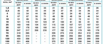
The table below shows hidden wiring for a single-phase housing connection to select a cable at a voltage of 220 volts.
As shown in the table, the cross-section of the cores also depends on the material from which it is made.
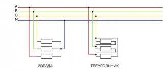
Three-phase network voltage 380 V
In three-phase power supply, the current strength is calculated using the following formula:
I = P /1.73 U
P - power consumption in watts;
U is the network voltage in volts.
In a 380 V technical phase power supply circuit, the formula is as follows:
I = P /657.4
If a three-phase 380 V network is connected to the house, then the connection diagram will look like this.
The table below shows the cross-sectional diagram of the cores in the power cable at various loads at a three-phase voltage of 380 V for hidden wiring.
For further calculation of power supply in load circuits characterized by high reactive apparent power, which is typical for the use of power supply in industry:
- electric motors;
- induction furnaces;
- chokes for lighting devices;
- welding transformers.
This phenomenon must be taken into account in further calculations. In more powerful electrical appliances, the load is much greater, so in calculations the power factor is taken to be 0.8.
When calculating the load on household appliances, the power reserve should be 5%. For the power grid, this percentage becomes 20%.
Source: https://DomStrouSam.ru/raschet-moshhnosti-po-toku-i-napryazheniyu-shema-i-tablitsyi/
An example of the possibility of starting a 380 V electric motor
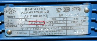
At the moment of starting the 4A250M2 U3 engine, the 4A250S2 U3 engine connected to the buses with a power of 75 kW and a terminal voltage of 365 V is running. The voltage on the 0.4 kV buses when starting the engine is Ush = 380 V.
1. Determine the long-term permissible current of motor D1:
where: Kstart = 7.5 – multiple of the starting current, according to the motor passport;
3. We determine the value of active and inductive resistance for an aluminum cable of the AAB brand with a cross-section of 3x70 mm2 for a voltage of 6 kV from the busbars of the 2RP-1 substation to a transformer of type TM 320 kVA, we take the resistance values from Table 2.5 [L2.s 48].
We obtain resistance values Rв = 0.447 Ohm/km and Хв = 0.08 Ohm/km.
These resistances must be brought to the low voltage side of the transformer since the motor is connected to the low voltage network. From Table 8 [L1, p. 93] for a nominal transformation ratio of 6/0.4 kV and a branch of 0% we find the value n=15.
4. We determine the active and inductive resistance of the cable in relation to the low voltage network using the formula [L1, p. 13]:
5. Determine the resistance of a cable 850 m long from the 2RP-1 substation to the 6/0.4 kV transformer:
6. We determine the resistance of a transformer with a power of 320 kVA, 6/0.4 kV according to Table 7 [L1, p. 92.93].
7. Determine the line resistance from the buses of the 2RP-1 substation to the low voltage buses of the substation:
8. Determine the resistance of an 80 m long AAB 3x95 mm2 cable from the low voltage busbars to the motor terminals:
Motor current calculation
The considered options for connecting industrial motors to a household network do not present much difficulty in their implementation. It is only important to pay close attention to some nuances and the equipment, although with a slight loss of power, will last a long time and be beneficial.
Expert opinion
It-Technology, Electrical power and electronics specialist
Ask questions to the “Specialist for modernization of energy generation systems”
Selection of circuit breakers for electric motors Standard values of electric motor power 0.25; 0.37; 0.55; 0.75; 1.1; 1.5; 2.2; 3.0; 4.0; 5.5; 7.5; eleven; 15; 18.5; 22; thirty; 37; 45; 55; 75 kW, etc. Ask, I’m in touch!
Calculation of single-phase and three-phase current
Good afternoon From this article you will learn what formulas are used to calculate single-phase and three-phase current, what parameters you need to know to perform the calculation and where to find them. And of course, I will give an example of calculating single-phase and three-phase currents.
where P is the power of the electrical receiver, W
U – supply voltage, V
cosφ – power factor
where P is the power of the electrical receiver, W
U – supply voltage, V
cosφ – power factor
For electric motors, it makes sense to take into account the coefficient of performance (efficiency), so the formulas take the following form:
where P is the power of the electrical receiver, W
U – supply voltage, V
cosφ – power factor
ɳ – efficiency
It can be noted that the formulas for calculating single-phase and three-phase currents are not complicated; all that remains is to figure out where to get the components for their calculation.
The power of the electrical receiver (P, W) can be found out from the passport that is attached to it or from the plate on the device body. If there is no such information, then on the Internet you can easily find the power of the required electrical receiver, but for this you need to know the exact name.
The supply voltage (U, B) when calculating single-phase electrical receivers is assumed to be 220V, and when calculating three-phase electrical consumers 380V. In practice, these values are usually different because the input voltage is slightly higher to prevent voltage loss. There are also cases when the input voltage is lower than the nominal voltage due to the great distance of the consumer, etc.
When calculating, the power factor cosφ (the ratio of active and apparent power) is taken from the data sheet for the electrical receiver, and if such information is not there, it is taken from reference books.
In the vast majority of cases, the cosφ value is unknown, but the average values for a particular type of consumer are known, and by substituting them you can perform the calculation. The ideal case is when cosφ = 1, but only heating elements, heaters, and incandescent lamps (0.99-1) can boast of such a value.
For electric motors, power factor values vary between 0.7-0.9, for fluorescent and LED lamps the power factor varies within (0.85-0.96), and for computers 0.6-0.8.
note
All of the above parameters can be measured experimentally, thereby checking the correctness of the calculations.
The efficiency is indicated in the passport for the electric motor.
Well, now I will give several examples of calculating currents.
Example 1. Let's take an electric kettle with a power of 2 kW. We know that it is connected to a 220V power supply, and we also know the power factor (0.99-1), which in this case we can ignore. Next, we take the formula for single-phase current and get:
Start capacitor
Also check out these articles
- Free bulletin boards on the Internet - a modern solution
- Advantages of modern multitools
- What is white spirit and why is it needed?
- Features of renting containers at an individual cargo storage warehouse
It is worth noting that on small electric motors used for domestic needs, for example, for a 200-400 W electric sharpener, you can not use a starting capacitor, but get by with one working capacitor, I have done this more than once - a working capacitor is quite enough. Another thing is if the electric motor starts with a significant load, then it is better to use a starting capacitor, which is connected in parallel with the working capacitor by pressing and holding the button while the electric motor accelerates, or using a special relay. The starting capacitor capacity is calculated by multiplying the working capacitor capacity by 2-2.5; this calculator uses 2.5.
It is worth remembering that as the asynchronous motor accelerates, it requires less capacitor capacity, i.e. You should not leave the starting capacitor connected for the entire operating time, because A large capacity at high speeds will cause overheating and failure of the electric motor.
How to calculate the power of an electric motor
How to calculate the power consumption of an asynchronous electric motor from the network if you can only find out the rated power from the nameplates? To do this you need:
- pay attention to the remaining indicators - these are η and cosφ (efficiency and power factor);
- take into account the relationship between the dynamic characteristics of the shaft and efficiency.
According to available data, it is possible to calculate the consumed electrical power:
P з=Р/η.
Calculations of the main parameters of an asynchronous electric motor
Active power is spent to perform useful work and create heat. Denoted by the letter " P ", measured in W and calculated:
P = I * U * cos φ.
Reactive power is created by fluctuations in the energy of the electric field. It determines the ability of jet engine parts to store and emit electromagnetic energy. We are talking about the current that charges a capacitor or creates a magnetic field around the turns of a coil winding. Denoted by the letter " Q ", measured in Var and calculated:
Q=I*U*sinφ.
The total power " S " is represented by a mathematical combination according to the formula of the Pythagorean theorem: S*S = Q*Q + P*P . It is measured in V*A and is calculated:
Important
S = P / cos φ = √(P2 + Q2)=I*U.
The reactive power of a three-phase asynchronous motor can be represented as the sum of two components: inductive and capacitive.
The best representation of this quantity can be obtained in the form of a vector diagram, the inductive component is a positive coordinate on the Y axis, the capacitive component is negative.
Obviously, these two values cancel each other out somewhat, making up a vector coordinate that will be either positive or negative.
The smaller the angle between them, the closer the total power becomes to the active one.
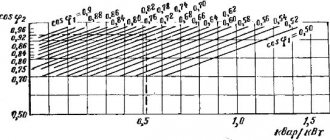
The power factor cosφ for a three-phase asynchronous motor is 0.8–0.9. If it needs to be increased, then quite often capacitors are added to the motor circuits. The function of these capacitors is to provide a magnetizing current that reduces the amplitude of the reactive component. The higher the cosφ , the less energy the electric machine consumes.
How to determine the power of an electric motor?
In order to perform the calculation, you will need measuring tools and reference information. So, there are options for determining the power of an electric motor:
- by current . We supply power to the asynchronous electric motor. We alternately measure the current in each coil with an ammeter. As a result, the average current value is multiplied by the voltage and the power consumption of the electric motor is obtained;
- by size . We measure the diameter and length of the stator core. Let's find out the shaft speed. Next, we make an approximate calculation of the “constant” using the formula:
3.14•D•n/(120•f).
Based on the calculation, we find a constant in the reference book. We calculate
P = C•D²•l•n•10^(-6);
- by traction force . We measure the speed of rotation of the shaft using a tachometer, the radius of the shaft with a regular ruler, and the traction force of the engine with a dynamometer. To calculate, we multiply all the found values
P = M • w = F •2•3.14• n • r .
Based on these mathematical expressions, we can conclude that asynchronous motors can have the same power, but differ in shaft speed, which significantly affects its dimensions. Let's also consider the meaning of using power regulators.
What types of regulators are there?
There are two types of regulators available on the market today:
- on a variable resistor,
- electronic (stepping and moving).
They all have different ways of controlling the rotation speed and, therefore, the efficiency (electricity consumption) of each type is different. From this point of view, the classic regulator is the cheapest, but ineffective. Let's look at all three types.
Variable resistor regulator
In fact, this rheostat has a huge coil inside. By choosing low speed settings, we are essentially choosing higher circuit resistance. This results in lower current consumption (since the voltage is a fixed value). The devices are bulky in size and inexpensive in price.
Electronic regulator
Electronic are the newest types of regulators available on the market. They are much smaller in size than others. To reduce the voltage, they use capacitors instead of resistors, which, by adjusting the rotation speed, control the power signal. Unlike rheostats, they do not heat up and, therefore, save electricity when the motor operates at low speeds.
Regulators can save up to 40% at “1st” speed and about 30% at “2nd” speed compared to their resistor counterparts. There are electronic types of regulators:
- movable with smooth adjustment.
- step-by-step with a numbered action speed (usually from 1 to 5).
These devices provide a low level of motor movement distortion and, therefore, heat less. An option with the best technology and energy savings.
Conclusion
The power of an asynchronous motor is the main technical characteristic of this device, which affects the scope of application and tasks performed.
Regulators are used to regulate the relationship of physical quantities.
Formulas expressing the relationship between the physical parameters of asynchronous motors do not need to be remembered all; they can be easily derived from those familiar from the school physics curriculum.
Source: https://ElectricDoma.ru/elektrodvigateli/kak-rasschitat-moshhnost-elektrodvigatelya/
Why do you need to know engine power?
Of all the technical characteristics of an electric motor (efficiency, rated operating current, speed, etc.), the most significant is power. Knowing the main data, you can:
- Select a thermal relay and automatic circuit breaker with suitable ratings.
- Determine the throughput and cross-section of electrical cables for connecting the unit.
- Operate the engine according to its parameters, avoiding overload.
We described how to measure the power of an electric motor in different ways. Use the one that is optimal in your case. Using any of the methods, you will select a unit that will best meet your requirements. But the most effective option, saving your time and eliminating the need to search for information and carry out measurements and calculations, is to keep the technical passport in a safe place and make sure that the data plate is not lost.
Connecting a direct starting motor, selecting all components
Almost every object contains motors that need to be connected. The bulk of electric motor equipment consists of fans and pumps. I think you noticed that I have just such a connection shown in the blog header. In this note we will connect an electric motor.
1 Calculate the current consumption of the motor.
Current consumption depends on power, voltage, power factor and efficiency. In some catalogs, for example Wilo pumps, in addition to power, the current consumption can also be found in the characteristics.
To calculate the motor current, you can use my program. Everything is very simple there. We substitute the data and get the calculated motor current. You can download my program for calculating the motor current at.
2 We determine how the engine will turn on.
As a rule, an electromagnetic starter is used to control the motor. An electromagnetic starter allows you to control the engine, if necessary, from two or more places. For example, a common ventilation system for two floors.