Connecting consumers to domestic or industrial electrical networks using a cable of less power than necessary can cause serious negative consequences. This will primarily cause circuit breakers to continually trip or fuses to blow. If unprotected, the power wire or cable may burn out. As a result of overheating, the insulation melts and a short circuit occurs between the wires. To avoid such situations, it is necessary to calculate the current by power and voltage in advance, depending on the existing single-phase or three-phase electrical network.
Why do you need current calculation?
Calculation of the current value in terms of power and voltage is carried out at the stage of designing the electrical networks of the facility. The data obtained allows you to correctly select the power cable to which consumers will connect. For current calculations, the value of the network voltage and the full load of electrical appliances is used. In accordance with the magnitude of the current, the cross-section of the cable cores and wires is selected.
If all consumers in a house or apartment are known in advance, then performing calculations is not particularly difficult. In the future, electrical installation work will be greatly simplified. In the same way, calculations are carried out for cables powering industrial equipment, mainly electric motors and other mechanisms.
Measuring power with a wattmeter
The power consumption of three-phase current is measured using wattmeters. This can be a special wattmeter for a 3-phase network, or a single-phase one connected according to a specific circuit. Modern electricity metering devices are often made using digital circuitry. Such designs are characterized by high measurement accuracy and greater capabilities for operating with input and output data.
Three-phase digital wattmeter
Measurement options:
- Star connection with neutral conductor and symmetrical load - the measuring device is connected to one of the lines, the readings taken are multiplied by three.
- Asymmetrical current consumption in a star connection - three wattmeters in the circuit of each phase. The wattmeter readings are summed up;
- Any load and delta connection - two wattmeters connected in a circuit of any two loads. The wattmeter readings are also summed up.
Measurement schemes
In practice, they always try to make the load symmetrical. This, firstly, improves network parameters, and secondly, simplifies the accounting of electrical energy.
Current calculation for a single-phase network
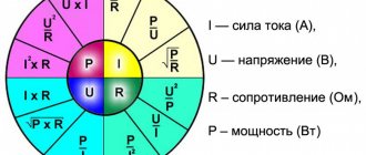
Current is measured in amperes. To calculate power and voltage, the formula is I = P/U, in which P is the power or total electrical load measured in watts. This parameter must be entered in the technical data sheet of the device. U – represents the voltage of the calculated network, measured in volts.
Power measurement
Wattmeters, special devices designed for this purpose, allow you to measure the power of three-phase circuits. Their number and connection methods depend on the specific electrical circuit: its characteristics and load connection diagram. Three-phase networks are distinguished by the number of supply wires and load distribution across phases, namely:
- three-wire system;
- four-wire system;
- uniform load;
- asymmetrical load.
Symmetrical load
If the system consists of four wires (3 phases and “zero”), and the load is evenly distributed between the phases, then in order to find out the total amount of power, it is enough to have one measuring device. The current winding of the wattmeter is connected in series to one of the linear wires, and the voltage winding of the measuring device is connected between the linear and neutral wires. This type of connection makes it possible to find out the number of watts in one phase. And since the load in the system is distributed evenly, the resulting power of the three-phase network is found by multiplying the obtained readings by the number of phases, that is, by 3.
Uneven distribution of consumers
Circuits with unbalanced loads on phases require the use of several wattmeters to determine the power characteristics. In a system consisting of four wires, you need to connect three devices so that the voltage windings of each are connected between the neutral wire and one of the phases. The overall result is found by summing the individual readings of each wattmeter.
A three-wire system will require a minimum of two wattmeters to determine the power of the entire circuit. The voltage windings of each individual wattmeter are connected to the input current clamp and the remaining free linear wire. The resulting readings are added up and the value of this value is obtained for a three-phase circuit. This circuit for connecting measuring instruments is based on Kirchhoff's first law.
Such nuances are very important when designing a three-phase network for the private sector. They should also be taken into account when properly servicing existing power supply systems.
Current calculation for a three-phase network
In the case of using a three-phase power supply, the current strength is calculated using the formula: I = P/1.73U, in which P means the power consumption, and U is the voltage in the three-phase network. 1.73 is a special coefficient used for three-phase networks.
Since the voltage in this case is 380 volts, the entire
formula will look like: I = P/657.4.
In the same way as in a single-phase network, the diameter and cross-section of conductors can be determined using a table showing the dependence of these parameters on various loads.
| Diameters of conductor cores (mm) | Conductor core cross-section (mm2) | Copper conductors | Aluminum conductors | ||
| Current (A) | Power, kWt) | Strength (A) | Power, kWt) | ||
| 0,8 | 0,5 | 6 | 2,25 | ||
| 0,98 | 0,75 | 10 | 3,8 | ||
| 1,13 | 1,0 | 14 | 5,3 | ||
| 1,38 | 1,5 | 15 | 5,7 | 10 | 3,8 |
| 1,6 | 2,0 | 19 | 7,2 | 14 | 5,3 |
| 1,78 | 2,5 | 21 | 7,9 | 16 | 6,0 |
| 2,26 | 4,0 | 27 | 10,0 | 21 | 7,9 |
| 2,76 | 6,0 | 34 | 12,0 | 26 | 9,8 |
| 3,57 | 10,0 | 50 | 19,0 | 38 | 14,0 |
| 4,51 | 16,0 | 80 | 30,0 | 55 | 20,0 |
| 5,64 | 25,0 | 100 | 38,0 | 65 | 24,0 |
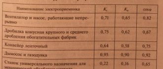
In some cases, the calculation of current by voltage and power should be carried out taking into account the total reactive power present in electric motors, welding and other equipment. For such devices, the power factor will be 0.8.
Determination of design loads taking into account single-phase receivers
Lecture No. 6.
Determination of design loads taking into account single-phase receivers.
At industrial enterprises, along with three-phase power receivers, there are stationary and mobile single-phase current receivers connected to phase or line voltage. When designing, they strive to distribute the power of single-phase receivers evenly across the phases of a three-phase network. However, this is not always possible. It is considered that the phase distribution of single-phase receivers is completed if the total rated power that remains undistributed evenly among the phases does not exceed 15% of the total load of the power supply system unit (the total power of three-phase and single-phase receivers distributed evenly among the phases). If the unevenness exceeds 15%, then the conditional three-phase rated power Rnom is determined. at
unevenly distributed receivers.
When the number of single-phase receivers unevenly distributed across phases is less than four Rnom. at
determined in simplified ways:
When switching on single-phase receivers to phase voltages Rnom. at
taken equal to triple the value of the rated power
Rnom.
m.f maximum loaded phase
Rnom. y=3 Rnom. m.f.
;
When switching on single-phase receivers to line voltage, the conditional three-phase rated power is determined by:
a) with one receiver
Rnom. y= ,
b) with two or three receivers connected to different line voltages of a three-phase network
Rnom. y=3rn. l
,
where is the rn. l
– rated power of the receiver of the most loaded phase.
If the number of unevenly distributed receivers is more than four, then the three-phase rated power is determined as triple the rated power of the most loaded phase. In this case, the most loaded phase is considered to be the phase with the highest average load from single-phase receivers. The average load of each phase with a mixed connection of single-phase receivers (the most general case), when some of the receivers are connected to phase voltage, and some to line voltage, is determined by summing the single-phase loads of this phase (phase-zero) and single-phase loads connected to line voltage, given to this phase and phase voltage using reduction coefficients.
Formulas for converting a single-phase load to a three-phase one:
,
,
,
where Rs. m
– average active load for the busiest shift,
Rn. AC
– maximum linear load,
r(AC)A
– coefficient of reduction of linear load to phase A.
The formulas for reducing reactive power are similar.
The most loaded phase is selected and the three-phase conditional load is determined based on its load:
Rs. m.u=3Rs. m.f. and
;
Qs. m.y=3 Qs.
m.f. ,
where Rs.
m.f and Qs.
mf average active and reactive loads of the maximum loaded phase.
When working together on a three-phase network of single-phase and three-phase electricity receivers, the calculated load of the power supply system node is determined by the formulas:
;
with an effective number of receivers
;
with an effective number of receivers
,
where n1,
m1
– the number of three-phase current receivers with variable and almost constant load patterns;
n2,
m2
- number of single-phase current receivers with variable and almost constant load schedules.
Determination of peak loads.
When designing power supply systems, peak current is considered as the peak load.
The peak current of a group of receivers operating at a lagging current is determined as the arithmetic sum of the largest of the starting currents of the motors included in the group and the rated current of the entire group of receivers minus the rated current of the motor having the highest starting current:
,
where ip. max
– the highest of the starting currents of the motors of the group of receivers, determined according to the passport data;
IP
– calculated current of the receiver group;
Ki. A
– utilization factor characteristic of the motor having the highest starting current;
Inom. max
– rated motor current (reduced to PV=1) with the highest starting current.
If the number of electricity receivers in a group is small and their installed capacities differ significantly from each other, then if there are powerful synchronous motors in this group, the peak current is determined by the formula:
,
where Рср.
m, Qavg.
m – respectively, the average active and reactive loads of the receivers of the group under consideration for the busiest shift;
rsr.
m, qavg.
m – average load of the engine being started for the busiest shift;
Km
– the maximum coefficient for groups of receivers, excluding the starting engine, can be taken equal to the maximum coefficient for active power found for the entire group.
The following is taken as the highest peak current of one receiver: for motors - the starting current, for furnace and welding transformers - the peak current, which is taken according to the passport data. In the absence of passport data, the starting current of asynchronous squirrel-cage and synchronous motors is taken equal to 5 times the rated current, the starting current of DC motors and asynchronous motors with a wound rotor is 2-2.5 times the rated current, the peak current of furnace and welding transformers is not less than 3 times the nominal (without reduction to PV=1).
When a group of motors self-starts, the sum of the starting currents of these motors is taken as the starting current.
Algorithm for determining design electrical loads.
1. Determination of the calculated electrical load of the ED group (the method of ordered diagrams is used).
Groups gather 10-12 EPs per group based on ki
and
cos j
.
neff
is determined for the group , then we find the design load
Рр
for the EP group.
S for all groups and find Рр S
,
Qр S
,
Spр S.
2 Determination of the calculated electrical loads of consumers (shops).
(or by ks
, or static).
If there are loads of different voltages in the workshop, then Рр
determined for consumers of each voltage separately.
3 When determined at higher levels of Рр
You must first take into account
DРр
,
D Qр
– losses in transformers.
To determine power losses in workshop transformers, simplified formulas are used:
,
.
First you need to sum up all the loads across the workshops.
4 Definition of PP
at the RP level.
The main task: each reactive power can be taken from high-voltage sources and we will use LEDs as Q
.
If we use SD, then we take Qn
SD is the power of the source, then:
QRP= Qp-QnSD
.
5 Determination of the design load of the enterprise as a whole.
,
krm
– coefficient of maximum different times.
PP0
– design lighting load.
Qе1
– the most economical reactive power for transmission from power systems to the enterprise power supply system in the maximum load mode.
Qe1=0.3Рр
Qp-( Qe1+ QSD)= Qku.
Qku –
power of compensating devices, i.e. the power that we must obtain from additional sources of reactive power.
— power received from the system.
Qku
=0 – no additional compensating devices are required.
Qku
0 by more than 10%, then the use of extra CU is economically unjustified.
Qku
>0 within 10%, then you can not install reactive power sources. If more, then you need to install a control unit.
The 10% spread can be explained by the fact that Qzap
CLEP.
Calculation of power by current and voltage
This calculation occurs based on the actual power; it must be done before you start designing your home (house, apartment).
- This value determines the cables that power the devices that are connected to the electrical network.
- Using the formula, you can calculate the current strength; for this you need to take the exact network voltage and the load of the powered devices. Its size gives us an idea of the cross-sectional area of the veins.
If you know all the electrical appliances that should be powered from the network in the future, then you can easily make calculations for the power supply diagram. The same calculations can be performed for production purposes.
Single-phase 220 volt network
Current formula I (A - amperes):
Where P is the electrical full load (its designation must be indicated in the technical data sheet of this device), W - watt;
U—mains voltage, V (volts).
The table shows the standard loads of electrical appliances and the current they consume (220 V).
| electrical appliance | Power consumption, W | Current strength, A |
| Washing machine | 2000 – 2500 | 9,0 – 11,4 |
| Jacuzzi | 2000 – 2500 | 9,0 – 11,4 |
| Electric floor heating | 800 – 1400 | 3,6 – 6,4 |
| Stationary electric stove | 4500 – 8500 | 20,5 – 38,6 |
| microwave | 900 – 1300 | 4,1 – 5,9 |
| Dishwasher | 2000 — 2500 | 9,0 – 11,4 |
| Freezers, refrigerators | 140 — 300 | 0,6 – 1,4 |
| Electric meat grinder | 1100 — 1200 | 5,0 — 5,5 |
| Electric kettle | 1850 – 2000 | 8,4 – 9,0 |
| Electric coffee maker | 6з0 — 1200 | 3,0 – 5,5 |
| Juicer | 240 — 360 | 1,1 – 1,6 |
| Toaster | 640 — 1100 | 2,9 — 5,0 |
| Mixer | 250 — 400 | 1,1 – 1,8 |
| Hairdryer | 400 — 1600 | 1,8 – 7,3 |
| Iron | 900 — 1700 | 4,1 – 7,7 |
| Vacuum cleaner | 680 — 1400 | 3,1 – 6,4 |
| Fan | 250 — 400 | 1,0 – 1,8 |
| TV | 125 — 180 | 0,6 – 0,8 |
| Radio equipment | 70 — 100 | 0,3 – 0,5 |
| Lighting devices | 20 — 100 | 0,1 – 0,4 |